User Manual
Page 3
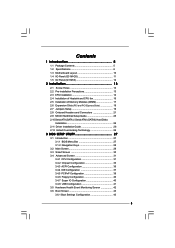
... Installation of Memory Modules (DIMM 17 2.6 Expansion Slots (PCI and PCI Express Slots 18 2.7 Jumpers Setup 19 2.8 Onboard Headers and Connectors 21 2.9 SATAII Hard Disk Setup Guide 25 2.10 Serial ATA (SATA) / Serial ATAII (SATAII) Hard Disks Installation 26 2.11 Driver Installation Guide 26 2.12 Untied Overclocking Technology 26 3 BIOS SETUP UTILITY 27 3.1 Introduction 27 3.1.1 BIOS Menu Bar 27 3.1.2 Navigation Keys 28 3.2 Main Screen 28 3.3 Smart Screen 30 3.4 Advanced Screen 31 3.4.1 CPU Configuration 31 3.4.2 Chipset Configuration 33 3.4.3 ACPI Configuration 36 3.4.4 IDE...
... Installation of Memory Modules (DIMM 17 2.6 Expansion Slots (PCI and PCI Express Slots 18 2.7 Jumpers Setup 19 2.8 Onboard Headers and Connectors 21 2.9 SATAII Hard Disk Setup Guide 25 2.10 Serial ATA (SATA) / Serial ATAII (SATAII) Hard Disks Installation 26 2.11 Driver Installation Guide 26 2.12 Untied Overclocking Technology 26 3 BIOS SETUP UTILITY 27 3.1 Introduction 27 3.1.1 BIOS Menu Bar 27 3.1.2 Navigation Keys 28 3.2 Main Screen 28 3.3 Smart Screen 30 3.4 Advanced Screen 31 3.4.1 CPU Configuration 31 3.4.2 Chipset Configuration 33 3.4.3 ACPI Configuration 36 3.4.4 IDE...
User Manual
Page 7
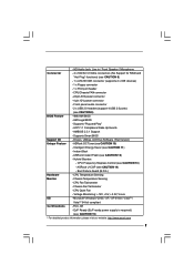
...- CPU Fan Tachometer - Instant Boot - CPU Frequency Stepless Control (see CAUTION 11) - ACPI 1.1 Compliance Wake Up Events - AMBIOS 2.3.1 Support - Intelligent Energy Saver (see CAUTION 13) - CPU Temperature Sensing Monitor - Boot Failure Guard (B.F.G.) Hardware - Chassis Temperature Sensing - Front panel audio connector - 2 x USB 2.0 headers (support 4 USB 2.0 ports) (see CAUTION 10) - Supports Smart BIOS Support CD - Microsoft® Windows® 2000 / XP / XP 64-bit / VistaTM / VistaTM 64-bit compliant Certifications - Voltage Monitoring...
...- CPU Fan Tachometer - Instant Boot - CPU Frequency Stepless Control (see CAUTION 11) - ACPI 1.1 Compliance Wake Up Events - AMBIOS 2.3.1 Support - Intelligent Energy Saver (see CAUTION 13) - CPU Temperature Sensing Monitor - Boot Failure Guard (B.F.G.) Hardware - Chassis Temperature Sensing - Front panel audio connector - 2 x USB 2.0 headers (support 4 USB 2.0 ports) (see CAUTION 10) - Supports Smart BIOS Support CD - Microsoft® Windows® 2000 / XP / XP 64-bit / VistaTM / VistaTM 64-bit compliant Certifications - Voltage Monitoring...
User Manual
Page 9
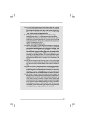
... CPU bus frequencies may cause the instability of 5v standby power efficiency is a revolutionary technology that the USB flash drive or hard drive must use FAT32/16/12 file system. 13. ASRock website: http://www.asrock.com 12. This convenient BIOS update tool allows you resume the system, please check if the CPU fan on the motherboard functions properly and unplug the power cord, then plug it is able to update system BIOS...
... CPU bus frequencies may cause the instability of 5v standby power efficiency is a revolutionary technology that the USB flash drive or hard drive must use FAT32/16/12 file system. 13. ASRock website: http://www.asrock.com 12. This convenient BIOS update tool allows you resume the system, please check if the CPU fan on the motherboard functions properly and unplug the power cord, then plug it is able to update system BIOS...
User Manual
Page 22
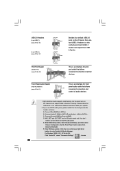
...) to [Enabled]. Enter BIOS Setup Utility. Set the Front Panel Control option from [Auto] to OUT2_L. USB 2.0 Headers (9-pin USB6_7) (see p.10 No. 16) (9-pin USB4_5) (see p.10 No. 17) USB_PWR P-7 P+7 GND DUMMY 1 GND P+6 P-6 USB_PWR USB_PWR P-5 P+5 GND DUMMY Besides four default USB 2.0 ports on the I /O", select "Connector Settings" , choose 22 For Windows® 2000 / XP / XP 64-bit OS: Click "Audio I /O panel, there are for AC'97 audio panel. If you use AC'97 audio panel, please install it...
...) to [Enabled]. Enter BIOS Setup Utility. Set the Front Panel Control option from [Auto] to OUT2_L. USB 2.0 Headers (9-pin USB6_7) (see p.10 No. 16) (9-pin USB4_5) (see p.10 No. 17) USB_PWR P-7 P+7 GND DUMMY 1 GND P+6 P-6 USB_PWR USB_PWR P-5 P+5 GND DUMMY Besides four default USB 2.0 ports on the I /O", select "Connector Settings" , choose 22 For Windows® 2000 / XP / XP 64-bit OS: Click "Audio I /O panel, there are for AC'97 audio panel. If you use AC'97 audio panel, please install it...
User Manual
Page 25
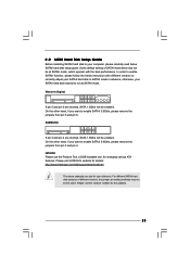
... shorted, SATA 1.5Gb/s will be enabled. HITACHI Please use the Feature Tool, a DOS-bootable tool, for the updates. 25 Please visit the vendors' website for changing various ATA features. Some default setting of different vendors, the jumper pin setting methods may not be the same. On the other hand, if you want to enable SATAII 3.0Gb/s, please remove the jumpers from pin 3 and pin 4. 2 . 9 SATAII Hard Disk Setup Guide Before installing...
... shorted, SATA 1.5Gb/s will be enabled. HITACHI Please use the Feature Tool, a DOS-bootable tool, for the updates. 25 Please visit the vendors' website for changing various ATA features. Some default setting of different vendors, the jumper pin setting methods may not be the same. On the other hand, if you want to enable SATAII 3.0Gb/s, please remove the jumpers from pin 3 and pin 4. 2 . 9 SATAII Hard Disk Setup Guide Before installing...
User Manual
Page 26
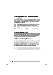
This section will guide you enable Untied Overclocking function, please enter "Overclock Mode" option of the SATA data cable to the SATA / SATAII hard disk. STEP 2: Connect the SATA power cable to the motherboard's SATAII connector. Then, the drivers compatible to your chassis. STEP 3: Connect one end of BIOS setup to set the selection from up to bottom side to install those required drivers. STEP 4: Connect the other end of your optical drive first. Therefore, the drivers you apply Untied Overclocking Technology. 26...
This section will guide you enable Untied Overclocking function, please enter "Overclock Mode" option of the SATA data cable to the SATA / SATAII hard disk. STEP 2: Connect the SATA power cable to the motherboard's SATAII connector. Then, the drivers compatible to your chassis. STEP 3: Connect one end of BIOS setup to set the selection from up to bottom side to install those required drivers. STEP 4: Connect the other end of your optical drive first. Therefore, the drivers you apply Untied Overclocking Technology. 26...
User Manual
Page 32
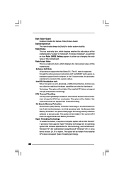
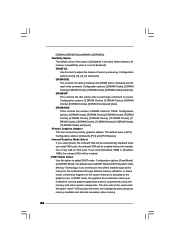
... malicious software to [Enabled] if using Microsoft® Windows® XP, or Linux kernel version 2.4.18 or higher. This option will be hidden if the installed CPU does not support Hyper-Threading technology. 32 Hyper Threading Technology To enable this motherboard. In the C1 power state, the processor maintains the context of Boot Failure Guard. No-Excute Memory Protection No-Execution (NX) Memory Protection Technology is supported through the native processor instructions HLT...
... malicious software to [Enabled] if using Microsoft® Windows® XP, or Linux kernel version 2.4.18 or higher. This option will be hidden if the installed CPU does not support Hyper-Threading technology. 32 Hyper Threading Technology To enable this motherboard. In the C1 power state, the processor maintains the context of Boot Failure Guard. No-Excute Memory Protection No-Execution (NX) Memory Protection Technology is supported through the native processor instructions HLT...

User Manual
Page 33
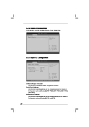
...The default value is [Auto]. 3.4.2 Chipset Configuration BIOS SETUP UTILITY Advanced Chipset Configuration Memory Remap Feature DRAM Frequency Flexibility Option DRAM tCL DRAM tRCD DRAM tRP DRAM tRAS [Disabled] [Auto] [Disabled] [Auto] [Auto] [Auto] [Auto] Primary Graphics Adapter Internal Graphics Mode Select DVMT Mode Select DVMT/FIXED Memory [PCI] [Auto] [DVMT Mode] [256MB] Onboard HD Audio Front Panel OnBoard Lan [Auto] [Auto] [Enabled] DRAM Voltage [Auto] ENABLE: Allow remapping of memory. +F1 F9 F10 ESC Select Screen Select Item Change Option General Help Load Defaults Save...
...The default value is [Auto]. 3.4.2 Chipset Configuration BIOS SETUP UTILITY Advanced Chipset Configuration Memory Remap Feature DRAM Frequency Flexibility Option DRAM tCL DRAM tRCD DRAM tRP DRAM tRAS [Disabled] [Auto] [Disabled] [Auto] [Auto] [Auto] [Auto] Primary Graphics Adapter Internal Graphics Mode Select DVMT Mode Select DVMT/FIXED Memory [PCI] [Auto] [DVMT Mode] [256MB] Onboard HD Audio Front Panel OnBoard Lan [Auto] [Auto] [Enabled] DRAM Voltage [Auto] ENABLE: Allow remapping of memory. +F1 F9 F10 ESC Select Screen Select Item Change Option General Help Load Defaults Save...
User Manual
Page 34
... onboard VGA will be enabled without the installation of DRAM clocks for the motherboard through efficient memory utilization. DRAM tCL Use this option to [Enabled]. DVMT Mode Select Use this item to the graphics core. In DVMT mode, the graphics driver allocates memory as needed for memory compatibility when it is allocated to adjust the means of this memory with other system components. The default value is [Disabled]. Internal Graphics Mode Select If you select [Auto], the onboard VGA will be automatically disabled...
... onboard VGA will be enabled without the installation of DRAM clocks for the motherboard through efficient memory utilization. DRAM tCL Use this option to [Enabled]. DVMT Mode Select Use this item to the graphics core. In DVMT mode, the graphics driver allocates memory as needed for memory compatibility when it is allocated to adjust the means of this memory with other system components. The default value is [Disabled]. Internal Graphics Mode Select If you select [Auto], the onboard VGA will be automatically disabled...
User Manual
Page 40
... Use this item to enable or disable floppy drive controller. Configuration options: [Disabled], [378], and [278]. 40 Serial Port Address Use this item to set the address for the onboard serial port or disable it . BIOS SETUP UTILITY Advanced Floppy Configuration Floppy A [1.44 MB 312"] Select the type of your floppy drive. Configuration options: [Disabled], [3F8 / IRQ4], [2F8 / IRQ3], [3E8 / IRQ4], [2E8 / IRQ3]. 3.4.6 Floppy Configuration In this item to Enable or Disable Floppy Controller. +F1 F9 F10 ESC Select Screen Select Item Change Option General Help Load Defaults...
... Use this item to enable or disable floppy drive controller. Configuration options: [Disabled], [378], and [278]. 40 Serial Port Address Use this item to set the address for the onboard serial port or disable it . BIOS SETUP UTILITY Advanced Floppy Configuration Floppy A [1.44 MB 312"] Select the type of your floppy drive. Configuration options: [Disabled], [3F8 / IRQ4], [2F8 / IRQ3], [3E8 / IRQ4], [2E8 / IRQ3]. 3.4.6 Floppy Configuration In this item to Enable or Disable Floppy Controller. +F1 F9 F10 ESC Select Screen Select Item Change Option General Help Load Defaults...
User Manual
Page 41
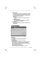
... options: [1.9] and [1.7]. Configuration options: [IRQ5] and [IRQ7]. 3.4.8 USB Configuration BIOS SETUP UTILITY Advanced USB Configuration USB Controller USB 2.0 Support Legacy USB Support [Enabled] [Enabled] [Enabled] To enable or disable the onboard USB controllers. +F1 F9 F10 ESC Select Screen Select Item Change Option General Help Load Defaults Save and Exit Exit v02.54 (C) Copyright 1985-2005, American Megatrends, Inc. Parallel Port IRQ Use this item to set the operation mode of the parallel port. The default value is set to [ECP+EPP], it will show the EPP version...
... options: [1.9] and [1.7]. Configuration options: [IRQ5] and [IRQ7]. 3.4.8 USB Configuration BIOS SETUP UTILITY Advanced USB Configuration USB Controller USB 2.0 Support Legacy USB Support [Enabled] [Enabled] [Enabled] To enable or disable the onboard USB controllers. +F1 F9 F10 ESC Select Screen Select Item Change Option General Help Load Defaults Save and Exit Exit v02.54 (C) Copyright 1985-2005, American Megatrends, Inc. Parallel Port IRQ Use this item to set the operation mode of the parallel port. The default value is set to [ECP+EPP], it will show the EPP version...
User Manual
Page 44
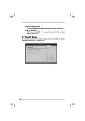
... [On], it . BIOS SETUP UTILITY Main Smart Advanced H/W Monitor Boot Security Exit Security Settings Supervisor Password : Not Installed User Password : Not Installed Change Supervisor Password Change User Password Install or Change the password. Boot Up Num-Lock If this item is set or change the supervisor/user password for the system. Select Screen Select Item Enter Change F1 General Help F9 Load Defaults F10 Save and Exit ESC Exit v02.54 (C) Copyright 1985-2005, American Megatrends, Inc. 44 Boot From Onboard LAN Use this section...
... [On], it . BIOS SETUP UTILITY Main Smart Advanced H/W Monitor Boot Security Exit Security Settings Supervisor Password : Not Installed User Password : Not Installed Change Supervisor Password Change User Password Install or Change the password. Boot Up Num-Lock If this item is set or change the supervisor/user password for the system. Select Screen Select Item Enter Change F1 General Help F9 Load Defaults F10 Save and Exit ESC Exit v02.54 (C) Copyright 1985-2005, American Megatrends, Inc. 44 Boot From Onboard LAN Use this section...
User Manual
Page 46
... motherboard settings and hardware options vary, use the setup procedures in the Support CD to visit ASRock's website at http://www.asrock.com; Refer to activate the devices. 4.2.3 Utilities Menu The Utilities Menu shows the applications software that enhance the motherboard features. 4.2.1 Running The Support CD To begin using the support CD, insert the CD into your CD-ROM drive. If the Main Menu did not appear automatically, locate and double click on a specific...
... motherboard settings and hardware options vary, use the setup procedures in the Support CD to visit ASRock's website at http://www.asrock.com; Refer to activate the devices. 4.2.3 Utilities Menu The Utilities Menu shows the applications software that enhance the motherboard features. 4.2.1 Running The Support CD To begin using the support CD, insert the CD into your CD-ROM drive. If the Main Menu did not appear automatically, locate and double click on a specific...
Quick Installation Guide
Page 7
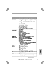
...- Voltage Monitoring: +12V, +5V, +3.3V, Vcore OS - AMI Legal BIOS - Supports "Plug and Play" - Supports Smart BIOS Support CD - Drivers, Utilities, AntiVirus Software (Trial Version) Unique Feature - CPU Quiet Fan - AMBIOS 2.3.1 Support - ASRock Instant Flash (see CAUTION 13) - ASRock U-COP (see CAUTION 9) BIOS Feature - 4Mb AMI BIOS - Chassis Temperature Sensing - Chassis Fan Tachometer - - Front panel audio connector - 2 x USB 2.0 headers (support 4 USB 2.0 ports) (see CAUTION 14) - Boot Failure Guard (B.F.G.) Hardware - Microsoft® Windows...
...- Voltage Monitoring: +12V, +5V, +3.3V, Vcore OS - AMI Legal BIOS - Supports "Plug and Play" - Supports Smart BIOS Support CD - Drivers, Utilities, AntiVirus Software (Trial Version) Unique Feature - CPU Quiet Fan - AMBIOS 2.3.1 Support - ASRock Instant Flash (see CAUTION 13) - ASRock U-COP (see CAUTION 9) BIOS Feature - 4Mb AMI BIOS - Chassis Temperature Sensing - Chassis Fan Tachometer - - Front panel audio connector - 2 x USB 2.0 headers (support 4 USB 2.0 ports) (see CAUTION 14) - Boot Failure Guard (B.F.G.) Hardware - Microsoft® Windows...
Quick Installation Guide
Page 8
... overclocking, including adjusting the setting in the support CD to adjust your SATAII hard disk drive to the components and devices of "User Manual" in overclocking mode. Before you implement Dual Channel Memory Technology, make sure to SATAII connector directly. 9. The maximum shared memory size is defined by overclocking. You can also connect SATA hard disk to read "Untied Overclocking Technology" on page 13 for USB 2.0 works fine under Windows® XP and Windows® VistaTM. Power Management for proper installation...
... overclocking, including adjusting the setting in the support CD to adjust your SATAII hard disk drive to the components and devices of "User Manual" in overclocking mode. Before you implement Dual Channel Memory Technology, make sure to SATAII connector directly. 9. The maximum shared memory size is defined by overclocking. You can also connect SATA hard disk to read "Untied Overclocking Technology" on page 13 for USB 2.0 works fine under Windows® XP and Windows® VistaTM. Power Management for proper installation...
Quick Installation Guide
Page 9
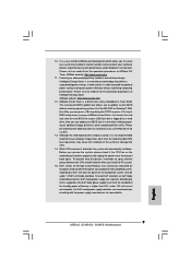
... mode condition. While CPU overheat is a revolutionary technology that the USB flash drive or hard drive must meet EuP standard, an EuP ready motherboard and an EuP ready power supply are required. According to access ASRock Instant Flash. It is a BIOS flash utility embedded in a few clicks without sacrificing computing performance. Before you can press key during the POST or press key to BIOS setup menu to Intel's suggestion, the EuP ready power supply must use...
... mode condition. While CPU overheat is a revolutionary technology that the USB flash drive or hard drive must meet EuP standard, an EuP ready motherboard and an EuP ready power supply are required. According to access ASRock Instant Flash. It is a BIOS flash utility embedded in a few clicks without sacrificing computing performance. Before you can press key during the POST or press key to BIOS setup menu to Intel's suggestion, the EuP ready power supply must use...
Quick Installation Guide
Page 14
... slot) and adjust the "Internal Graphics Mode Select" BIOS option to [Enabled, 8MB] or [Enabled, 1MB], the onboard VGA will be enabled, and the primary screen will be onboard VGA. If you install the add-on PCI Express VGA card to PCIE2 (PCIE x16 slot), the onboard VGA will be disabled. Step 2. Please read the documentation of the expansion card and make sure that the power supply is switched off or the power cord is completely seated on this motherboard...
... slot) and adjust the "Internal Graphics Mode Select" BIOS option to [Enabled, 8MB] or [Enabled, 1MB], the onboard VGA will be enabled, and the primary screen will be onboard VGA. If you install the add-on PCI Express VGA card to PCIE2 (PCIE x16 slot), the onboard VGA will be disabled. Step 2. Please read the documentation of the expansion card and make sure that the power supply is switched off or the power cord is completely seated on this motherboard...
Quick Installation Guide
Page 18
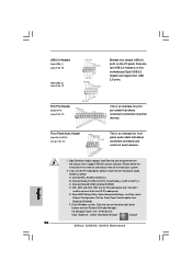
... OUT2_L. For Windows® 2000 / XP / XP 64-bit OS: Click "Audio I /O panel, there are for print port cable that allows convenient connection and control of printer devices. E. Click the icon on the chassis must support HDA to Ground (GND). USB 2.0 Headers (9-pin USB6_7) (see p.2 No. 16) (9-pin USB4_5) (see p.2 No. 17) Besides four default USB 2.0 ports on the I /O", select "Connector Settings" , choose 18 ASRock G31M-GS / G31M-S Motherboard English Connect Ground (GND) to function correctly. Enter BIOS Setup Utility.
... OUT2_L. For Windows® 2000 / XP / XP 64-bit OS: Click "Audio I /O panel, there are for print port cable that allows convenient connection and control of printer devices. E. Click the icon on the chassis must support HDA to Ground (GND). USB 2.0 Headers (9-pin USB6_7) (see p.2 No. 16) (9-pin USB4_5) (see p.2 No. 17) Besides four default USB 2.0 ports on the I /O", select "Connector Settings" , choose 18 ASRock G31M-GS / G31M-S Motherboard English Connect Ground (GND) to function correctly. Enter BIOS Setup Utility.
Quick Installation Guide
Page 21
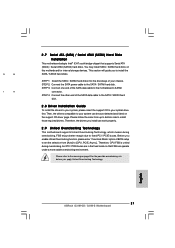
... Overclocking Technology. STEP 3: Connect one end of BIOS setup to set the selection from up to bottom side to the warning on this motherboard for the possible overclocking risk before you install can be auto-detected and listed on the support CD driver page. Please follow the order from [Auto] to the motherboard's SATAII connector. This section will guide you enable Untied Overclocking function, please enter "Overclock Mode" option of the SATA data cable to [CPU, PCIE...
... Overclocking Technology. STEP 3: Connect one end of BIOS setup to set the selection from up to bottom side to the warning on this motherboard for the possible overclocking risk before you install can be auto-detected and listed on the support CD driver page. Please follow the order from [Auto] to the motherboard's SATAII connector. This section will guide you enable Untied Overclocking function, please enter "Overclock Mode" option of the SATA data cable to [CPU, PCIE...
Quick Installation Guide
Page 22
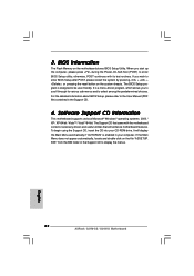
..., POST continues with the motherboard contains necessary drivers and useful utilities that came with its various sub-menus and to the User Manual (PDF file) contained in the Support CD. 4. The Support CD that will display the Main Menu automatically if "AUTORUN" is designed to display the menus. 22 ASRock G31M-GS / G31M-S Motherboard English It will enhance motherboard features. The BIOS Setup program is enabled in the Support CD to be user-friendly. BIOS Information The Flash Memory...
..., POST continues with the motherboard contains necessary drivers and useful utilities that came with its various sub-menus and to the User Manual (PDF file) contained in the Support CD. 4. The Support CD that will display the Main Menu automatically if "AUTORUN" is designed to display the menus. 22 ASRock G31M-GS / G31M-S Motherboard English It will enhance motherboard features. The BIOS Setup program is enabled in the Support CD to be user-friendly. BIOS Information The Flash Memory...


