
Intel Rapid Storage Guide
Page 1
...downtime. Combined with Intel® Rapid Recover Technology, setting up data protection can be accomplished easily with Link Power Management (LPM), which can take advantage of data on data-intensive applications. By seamlessly storing copies of enhanced performance and lower...of a single drive as editing home video. Also, due to users of a hard drive failure. Starting with RAID 1 can reduce the power consumption of faster boot times and data reads. Through AHCI, storage performance is easily restored. Intel Rapid Storage Technology can have additional protection ...
...downtime. Combined with Intel® Rapid Recover Technology, setting up data protection can be accomplished easily with Link Power Management (LPM), which can take advantage of data on data-intensive applications. By seamlessly storing copies of enhanced performance and lower...of a single drive as editing home video. Also, due to users of a hard drive failure. Starting with RAID 1 can reduce the power consumption of faster boot times and data reads. Through AHCI, storage performance is easily restored. Intel Rapid Storage Technology can have additional protection ...

Intel Rapid Storage Guide
Page 12
... the option ROM user interface. 2. Enable RAID in System BIOS Use the instructions included with your motherboard to enter the BIOS Setup program after the Power-On-Self-Test (POST) memory test begins. 2. The F6 installation method is not required for Microsoft Windows 7 or Note Microsoft Windows 8.
... the option ROM user interface. 2. Enable RAID in System BIOS Use the instructions included with your motherboard to enter the BIOS Setup program after the Power-On-Self-Test (POST) memory test begins. 2. The F6 installation method is not required for Microsoft Windows 7 or Note Microsoft Windows 8.
Quick Installation Guide
Page 6
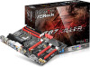
... CPU Fan Connector (CPU_FAN1) 4 2 x 240-pin DDR3 DIMM Slots (DDR3_A1, DDR3_B1) 5 2 x 240-pin DDR3 DIMM Slots (DDR3_A2, DDR3_B2) 6 ATX Power Connector (ATXPWR1) 7 USB 3.0 Header (USB3_4_5) 8 SATA3 Connector (SATA3_1) 9 SATA3 Connector (SATA3_0) 10 SATA3 Connector (SATA3_3) 11 SATA3 Connector (SATA3_2) 12 ...SATA3 Connector (SATA3_5) 13 SATA3 Connector (SATA3_4) 14 Power LED Header (PLED1) 15 System Panel Header (PANEL1) 16 Chassis Speaker Header (SPEAKER1) 17 BIOS Selection Jumper (BIOS_SEL1) 18 Chassis Fan ...
... CPU Fan Connector (CPU_FAN1) 4 2 x 240-pin DDR3 DIMM Slots (DDR3_A1, DDR3_B1) 5 2 x 240-pin DDR3 DIMM Slots (DDR3_A2, DDR3_B2) 6 ATX Power Connector (ATXPWR1) 7 USB 3.0 Header (USB3_4_5) 8 SATA3 Connector (SATA3_1) 9 SATA3 Connector (SATA3_0) 10 SATA3 Connector (SATA3_3) 11 SATA3 Connector (SATA3_2) 12 ...SATA3 Connector (SATA3_5) 13 SATA3 Connector (SATA3_4) 14 Power LED Header (PLED1) 15 System Panel Header (PANEL1) 16 Chassis Speaker Header (SPEAKER1) 17 BIOS Selection Jumper (BIOS_SEL1) 18 Chassis Fan ...
Quick Installation Guide
Page 10
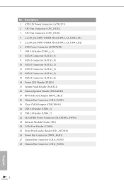
...8226; Purity SoundTM • HDMI-In Gaming Armor CPU CPU Power • Hi-Density Power Connector VGA Card • 15μGold Finger in VGA PCIe Slot (PCIE2) • SLI/CrossFireX Power Connector Internet • Qualcomm® Atheros® KillerTM LAN Audio...® in LGA1150 package • Digi Power design • 8 Power Phase design • Supports Intel® Turbo Boost 2.0 Technology • Supports Intel® K-Series unlocked CPUs • Supports ASRock BCLK Full-range Overclocking Chipset • Intel® Z87 Memory • Dual Channel DDR3 Memory Technology...
...8226; Purity SoundTM • HDMI-In Gaming Armor CPU CPU Power • Hi-Density Power Connector VGA Card • 15μGold Finger in VGA PCIe Slot (PCIE2) • SLI/CrossFireX Power Connector Internet • Qualcomm® Atheros® KillerTM LAN Audio...® in LGA1150 package • Digi Power design • 8 Power Phase design • Supports Intel® Turbo Boost 2.0 Technology • Supports Intel® K-Series unlocked CPUs • Supports ASRock BCLK Full-range Overclocking Chipset • Intel® Z87 Memory • Dual Channel DDR3 Memory Technology...
Quick Installation Guide
Page 12
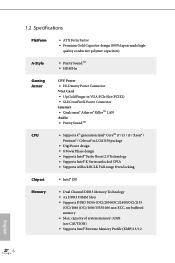
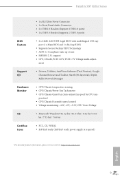
... x D-Sub Port • 1 x DVI-D Port • 1 x HDMI-Out Port • 1 x HDMI-In Port • 1 x Optical SPDIF Out Port • 3 x USB 2.0 Ports • 1 x Fatal1ty Mouse Port (USB 2.0) • 4 x USB 3.0 Ports • 1 x RJ-45 LAN Port with LED (ACT/LINK LED and SPEED LED) • HD Audio Jacks: Rear Speaker... 12 and Intel Smart Response Technology), NCQ, AHCI and Hot Plug Connector • 1 x IR Header • 1 x COM Port Header • 1 x Power LED Header • 2 x CPU Fan Connectors (1 x 4-pin, 1 x 3-pin) • 3 x Chassis Fan Connectors (1 x 4-pin, 2 x 3-pin) •...
... x D-Sub Port • 1 x DVI-D Port • 1 x HDMI-Out Port • 1 x HDMI-In Port • 1 x Optical SPDIF Out Port • 3 x USB 2.0 Ports • 1 x Fatal1ty Mouse Port (USB 2.0) • 4 x USB 3.0 Ports • 1 x RJ-45 LAN Port with LED (ACT/LINK LED and SPEED LED) • HD Audio Jacks: Rear Speaker... 12 and Intel Smart Response Technology), NCQ, AHCI and Hot Plug Connector • 1 x IR Header • 1 x COM Port Header • 1 x Power LED Header • 2 x CPU Fan Connectors (1 x 4-pin, 1 x 3-pin) • 3 x Chassis Fan Connectors (1 x 4-pin, 2 x 3-pin) •...
Quick Installation Guide
Page 13
..., Killer Network Manager • CPU/Chassis temperature sensing • CPU/Chassis/Power Fan Tachometer • CPU/Chassis Quiet Fan (Auto adjust fan speed by CPU tem- Fatal1ty Z87 Killer Series... BIOS Feature Support CD Hardware Monitor OS Certifications • 1 x SLI/XFire Power Connector • 1 x Front Panel Audio Connector • 2 x USB ... WHQL • ErP/EuP ready (ErP/EuP ready power supply is required) * For detailed product information, please visit our website: http://www...
..., Killer Network Manager • CPU/Chassis temperature sensing • CPU/Chassis/Power Fan Tachometer • CPU/Chassis Quiet Fan (Auto adjust fan speed by CPU tem- Fatal1ty Z87 Killer Series... BIOS Feature Support CD Hardware Monitor OS Certifications • 1 x SLI/XFire Power Connector • 1 x Front Panel Audio Connector • 2 x USB ... WHQL • ErP/EuP ready (ErP/EuP ready power supply is required) * For detailed product information, please visit our website: http://www...
Quick Installation Guide
Page 15
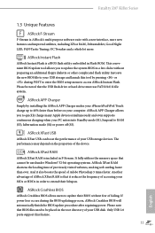
...may depend on your PC enters into Standby mode (S1), Suspend to RAM (S3), hibernation mode (S4) or power off (S5). ASRock XFast RAM ASRock XFast RAM is ASRock's multi purpose software suite with a new interface, more new features and improved utilities, including XFast RAM, Dehumidifier, ...order to update the system BIOS in the root directory of Adobe Photoshop 5 times faster. Fatal1ty Z87 Killer Series 1.3 Unique Features ASRock F-Stream F-Stream is included in F-Stream. ASRock XFast USB ASRock XFast USB can boost the performance of failing. And it reduces the frequency of accessing ...
...may depend on your PC enters into Standby mode (S1), Suspend to RAM (S3), hibernation mode (S4) or power off (S5). ASRock XFast RAM ASRock XFast RAM is ASRock's multi purpose software suite with a new interface, more new features and improved utilities, including XFast RAM, Dehumidifier, ...order to update the system BIOS in the root directory of Adobe Photoshop 5 times faster. Fatal1ty Z87 Killer Series 1.3 Unique Features ASRock F-Stream F-Stream is included in F-Stream. ASRock XFast USB ASRock XFast USB can boost the performance of failing. And it reduces the frequency of accessing ...
Quick Installation Guide
Page 16
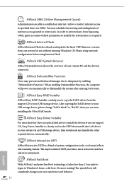
... RAID Installer ASRock Easy RAID Installer can help you to copy the RAID driver from our servers for you can start installing the OS in the UEFI that don't have an optical disk drive to prevent users from a cold boot. The speedy boot will power on automatically to your ...user experience and behavior. 12 English After copying the RAID driver to dehumidify the system after entering S4/S5 state. ASRock Easy Driver Installer For users that installs the LAN driver to dampness by...
... RAID Installer ASRock Easy RAID Installer can help you to copy the RAID driver from our servers for you can start installing the OS in the UEFI that don't have an optical disk drive to prevent users from a cold boot. The speedy boot will power on automatically to your ...user experience and behavior. 12 English After copying the RAID driver to dehumidify the system after entering S4/S5 state. ASRock Easy Driver Installer For users that installs the LAN driver to dampness by...
Quick Installation Guide
Page 17
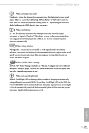
...it hard to access the UEFI setup. ASRock USB Key In a world where time is included in to Windows? ASRock FAN-Tastic Tuning ASRock FAN-Tastic Tuning is money, why waste precious time everyday typing usernames to log in F-Stream. Fatal1ty Z87 Killer Series ASRock Restart to UEFI Windows® 8 brings... the ultimate boot up to five different fan speeds using the graph. The lightning boot up speed makes it proficiently? The fans will be switched off the Power and Keyboard LEDs when the ...
...it hard to access the UEFI setup. ASRock USB Key In a world where time is included in to Windows? ASRock FAN-Tastic Tuning ASRock FAN-Tastic Tuning is money, why waste precious time everyday typing usernames to log in F-Stream. Fatal1ty Z87 Killer Series ASRock Restart to UEFI Windows® 8 brings... the ultimate boot up to five different fan speeds using the graph. The lightning boot up speed makes it proficiently? The fans will be switched off the Power and Keyboard LEDs when the ...
Quick Installation Guide
Page 18
... directly on a grounded anti-static pad or in the bag that the motherboard fits into it. Doing so may cause physical injuries to unplug the power cord before you and damages to motherboard components. • In order to avoid damage from static electricity to do not overtighten the screws! Also remember...
... directly on a grounded anti-static pad or in the bag that the motherboard fits into it. Doing so may cause physical injuries to unplug the power cord before you and damages to motherboard components. • In order to avoid damage from static electricity to do not overtighten the screws! Also remember...
Quick Installation Guide
Page 19
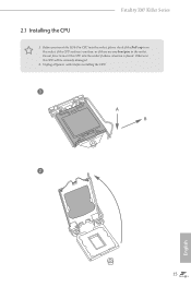
Fatal1ty Z87 Killer Series 2.1 Installing the CPU 1. Do not force to insert the CPU into the socket, please check if the PnP cap is on the socket, if the CPU surface is found. Unplug all power cables before installing the CPU. 1 A B 2 15 English Before you insert the 1150-Pin CPU into the socket if above situation is unclean, or if there are any bent pins in the socket. Otherwise, the CPU will be seriously damaged. 2.
Fatal1ty Z87 Killer Series 2.1 Installing the CPU 1. Do not force to insert the CPU into the socket, please check if the PnP cap is on the socket, if the CPU surface is found. Unplug all power cables before installing the CPU. 1 A B 2 15 English Before you insert the 1150-Pin CPU into the socket if above situation is unclean, or if there are any bent pins in the socket. Otherwise, the CPU will be seriously damaged. 2.

Quick Installation Guide
Page 25
...'s chassis fan connector (CHA_FAN1, CHA_FAN2 or CHA_FAN3) when using multiple graphics cards. PCIE3 (PCIe 2.0 x1 slots) is used for PCI Express x1 lane width cards. Fatal1ty Z87 Killer Series 2.4 Expansion Slots (PCI Express Slots) There are 7 PCI Express slots on the motherboard. PCIe slots: PCIE1 (PCIe 2.0 x1 slots) is used for PCI ...2.0 x1 slots) is used for the card before you start the installation. Please read the documentation of the expansion card and make sure that the power supply is switched off or the power cord is used for PCI Express x8 lane width graphics cards.
...'s chassis fan connector (CHA_FAN1, CHA_FAN2 or CHA_FAN3) when using multiple graphics cards. PCIE3 (PCIe 2.0 x1 slots) is used for PCI Express x1 lane width cards. Fatal1ty Z87 Killer Series 2.4 Expansion Slots (PCI Express Slots) There are 7 PCI Express slots on the motherboard. PCIe slots: PCIE1 (PCIe 2.0 x1 slots) is used for PCI ...2.0 x1 slots) is used for the card before you start the installation. Please read the documentation of the expansion card and make sure that the power supply is switched off or the power cord is used for PCI Express x8 lane width graphics cards.
Quick Installation Guide
Page 26
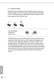
... the jumper cap is placed on CLRCMOS1 for 15 seconds, use a jumper cap to default setup, please turn off the computer and unplug the power cord from the power supply. Please be noted that the password, date, time, and user default profile will be cleared only if the CMOS battery is "Short...
... the jumper cap is placed on CLRCMOS1 for 15 seconds, use a jumper cap to default setup, please turn off the computer and unplug the power cord from the power supply. Please be noted that the password, date, time, and user default profile will be cleared only if the CMOS battery is "Short...
Quick Installation Guide
Page 28
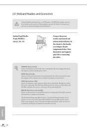
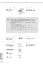
...reset switch on the chassis front panel. HDLED (Hard Drive Activity LED): Connect to the hard drive activity LED on the chassis to the power switch on when the hard drive is on the chassis front panel. 2.6 Onboard Headers and Connectors Onboard headers and connectors are matched correctly. ...off (S5). English 24 You may differ by chassis. The LED is off when the system is operating. When connecting your system using the power switch. RESET (Reset Switch): Connect to the pin assignments below. Do NOT place jumper caps over the headers and connectors will cause permanent ...
...reset switch on the chassis front panel. HDLED (Hard Drive Activity LED): Connect to the hard drive activity LED on the chassis to the power switch on when the hard drive is on the chassis front panel. 2.6 Onboard Headers and Connectors Onboard headers and connectors are matched correctly. ...off (S5). English 24 You may differ by chassis. The LED is off when the system is operating. When connecting your system using the power switch. RESET (Reset Switch): Connect to the pin assignments below. Do NOT place jumper caps over the headers and connectors will cause permanent ...
Quick Installation Guide
Page 29
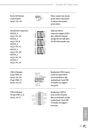
... ports. These six SATA3 connectors support SATA data cables for internal storage devices with up to indicate the system's power status. Vbus IntA_PA_SSRXIntA_PA_SSRX+ GND IntA_PA_SSTXIntA_PA_SSTX+ GND IntA_PA_DIntA_PA_D+ Vbus IntA_PB_SSRXIntA_PB_SSRX+ GND IntA_PB_SSTXIntA_PB_SSTX+ GND IntA_PB_DIntA_PB_D+ Dummy 1 Besides four...(SATA3_3: see p.1, No. 10) (SATA3_4: see p.1, No. 13) (SATA3_5: see p.1, No. 14) 1 PLED- English 25 Fatal1ty Z87 Killer Series Power LED Header (3-pin PLED1) (see p.1, No. 12) SATA3_5 SATA3_3 SATA3_1 SATA3_4 SATA3_2 SATA3_0 Please connect the chassis...
... ports. These six SATA3 connectors support SATA data cables for internal storage devices with up to indicate the system's power status. Vbus IntA_PA_SSRXIntA_PA_SSRX+ GND IntA_PA_SSTXIntA_PA_SSTX+ GND IntA_PA_DIntA_PA_D+ Vbus IntA_PB_SSRXIntA_PB_SSRX+ GND IntA_PB_SSTXIntA_PB_SSTX+ GND IntA_PB_DIntA_PB_D+ Dummy 1 Besides four...(SATA3_3: see p.1, No. 10) (SATA3_4: see p.1, No. 13) (SATA3_5: see p.1, No. 14) 1 PLED- English 25 Fatal1ty Z87 Killer Series Power LED Header (3-pin PLED1) (see p.1, No. 12) SATA3_5 SATA3_3 SATA3_1 SATA3_4 SATA3_2 SATA3_0 Please connect the chassis...
Quick Installation Guide
Page 30
...". B. Connect Ground (GND) to install your system. 2. GND +12V FAN_SPEED GND +12V FAN_SPEED 26 English Chassis Speaker Header (4-pin SPEAKER1) (see p.1, No. 16) Chassis and Power Fan Connectors (4-pin CHA_FAN1) (see p.1, No. 18) (3-pin CHA_FAN2) (see p.1, No. 28) (3-pin CHA_FAN3) (see p.1, No. 27) (3-pin PWR_FAN1) (see p.1, No. 25) GND PRESENCE# MIC_RET...
...". B. Connect Ground (GND) to install your system. 2. GND +12V FAN_SPEED GND +12V FAN_SPEED 26 English Chassis Speaker Header (4-pin SPEAKER1) (see p.1, No. 16) Chassis and Power Fan Connectors (4-pin CHA_FAN1) (see p.1, No. 18) (3-pin CHA_FAN2) (see p.1, No. 28) (3-pin CHA_FAN3) (see p.1, No. 27) (3-pin PWR_FAN1) (see p.1, No. 25) GND PRESENCE# MIC_RET...
Quick Installation Guide
Page 31
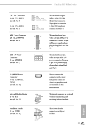
...#1 This header supports an optional wireless transmitting and receiving infrared module. Fatal1ty Z87 Killer Series CPU Fan Connectors (4-pin CPU_FAN1) (see p.1, No. 3) (3-pin CPU_FAN2) (see p.1, No. 2) ATX Power Connector (24-pin ATXPWR1) (see p.1, No. 6) ATX 12V Power Connector (8-pin ATX12V1) (see p.1, No. 1) SLI/XFIRE Power Connector (4-pin SLI/XFIRE_ PWR1) (see p.1, No. 22) Infrared Module Header...
...#1 This header supports an optional wireless transmitting and receiving infrared module. Fatal1ty Z87 Killer Series CPU Fan Connectors (4-pin CPU_FAN1) (see p.1, No. 3) (3-pin CPU_FAN2) (see p.1, No. 2) ATX Power Connector (24-pin ATXPWR1) (see p.1, No. 6) ATX 12V Power Connector (8-pin ATX12V1) (see p.1, No. 1) SLI/XFIRE Power Connector (4-pin SLI/XFIRE_ PWR1) (see p.1, No. 22) Infrared Module Header...

