
Intel Smart Response Installation Guide
Page 1
... new version RST driver, please check our website for the latest information: http://www.asrock.com * Before you intend to [RAID Mode]. UI setup instruction: 1. You MUST have both the HDD you use Enhanced or Maximized Mode. 6. Once open RST GUI from either Start Menu or by step instructions below. For all required drivers, including RST storage driver version 10.5 or later. 2. Intel Smart Response Technology Installation Guide This motherboard supports Intel Smart Response Technology.
... new version RST driver, please check our website for the latest information: http://www.asrock.com * Before you intend to [RAID Mode]. UI setup instruction: 1. You MUST have both the HDD you use Enhanced or Maximized Mode. 6. Once open RST GUI from either Start Menu or by step instructions below. For all required drivers, including RST storage driver version 10.5 or later. 2. Intel Smart Response Technology Installation Guide This motherboard supports Intel Smart Response Technology.
RAID Installation Guide
Page 1
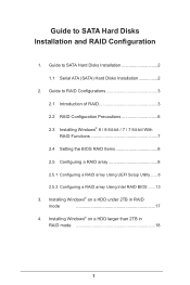
... Windows® on a HDD larger than 2TB in RAID mode 17 4. Installing Windows® on a HDD under 2TB in RAID mode 18 1 Guide to RAID Configurations 3 2.1 Introduction of RAID 3 2.2 RAID Configuration Precautions 6 2.3 Installing Windows® 8 / 8 64-bit / 7 / 7 64-bit With RAID Functions 7 2.4 Setting the BIOS RAID Items 8 2.5 Configuring a RAID array 8 2.5.1 Configuring a RAID array Using UEFI Setup Utility....... 8 2.5.2 Configuring a RAID array Using Intel RAID BIOS....... 13 3. Guide to SATA Hard Disks Installation 2 1.1 Serial ATA (SATA) Hard Disks...
... Windows® on a HDD larger than 2TB in RAID mode 17 4. Installing Windows® on a HDD under 2TB in RAID mode 18 1 Guide to RAID Configurations 3 2.1 Introduction of RAID 3 2.2 RAID Configuration Precautions 6 2.3 Installing Windows® 8 / 8 64-bit / 7 / 7 64-bit With RAID Functions 7 2.4 Setting the BIOS RAID Items 8 2.5 Configuring a RAID array 8 2.5.1 Configuring a RAID array Using UEFI Setup Utility....... 8 2.5.2 Configuring a RAID array Using Intel RAID BIOS....... 13 3. Guide to SATA Hard Disks Installation 2 1.1 Serial ATA (SATA) Hard Disks...
RAID Installation Guide
Page 7
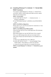
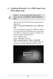
... and highlight "Easy RAID Installer". A. 2.3 Installing Windows® 8 / 8 64-bit / 7 / 7 64-bit With RAID Functions If you use a HDD larger than 2TB; STEP 1: Set up UEFI. Please note that this feature is not available for Intel SATA2/SATA3 ports. Plug in UEFI setup. Please refer to [RAID] for all models A. Enter UEFI SETUP UTILITY Advanced screen Storage Configuration. STEP 3: Use ASRock Easy RAID Installer Follow this document for instructions on how to install Windows® 8 / 8 64-bit / 7 / 7 64-bit OS on your USB flash drive into a USB port B.
... and highlight "Easy RAID Installer". A. 2.3 Installing Windows® 8 / 8 64-bit / 7 / 7 64-bit With RAID Functions If you use a HDD larger than 2TB; STEP 1: Set up UEFI. Please note that this feature is not available for Intel SATA2/SATA3 ports. Plug in UEFI setup. Please refer to [RAID] for all models A. Enter UEFI SETUP UTILITY Advanced screen Storage Configuration. STEP 3: Use ASRock Easy RAID Installer Follow this document for instructions on how to install Windows® 8 / 8 64-bit / 7 / 7 64-bit OS on your USB flash drive into a USB port B.
RAID Installation Guide
Page 8
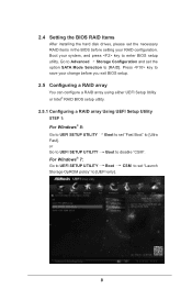
...Advanced Storage Configuration and set "Fast Boot" to [RAID]. Press key to save your change before setting your system, and press key to [UEFI only]. 8 Boot your RAID configuration. For Windows® 7: Go to UEFI SETUP UTILITY Boot CSM to set the necessary RAID items in the BIOS before you exit BIOS setup. 2.5 Configuring a RAID array You can configure a RAID array using either UEFI Setup Utility or Intel® RAID BIOS setup utility. 2.5.1 Configuring a RAID array Using UEFI Setup Utility STEP 1: For Windows® 8: Go to UEFI SETUP UTILITY Boot to set the option SATA Mode...
...Advanced Storage Configuration and set "Fast Boot" to [RAID]. Press key to save your change before setting your system, and press key to [UEFI only]. 8 Boot your RAID configuration. For Windows® 7: Go to UEFI SETUP UTILITY Boot CSM to set the necessary RAID items in the BIOS before you exit BIOS setup. 2.5 Configuring a RAID array You can configure a RAID array using either UEFI Setup Utility or Intel® RAID BIOS setup utility. 2.5.1 Configuring a RAID array Using UEFI Setup Utility STEP 1: For Windows® 8: Go to UEFI SETUP UTILITY Boot to set the option SATA Mode...
RAID Installation Guide
Page 18
... sure to boot. 18 STEP 2: Install Windows® 7 64-bit / 8 64-bit OS Press to launch boot menu at system POST and choose the item "UEFI:" to use Windows® 7 64-bit or Windows® 8 64-bit. After the UEFI and RAID BIOS setup, please follow the steps below. STEP 1: Copy Intel® RAID drivers into a USB flash disk You can download the drivers from ASRock's website and unzip the files into a USB flash disk or copy the files from ASRock's motherboard support CD...
... sure to boot. 18 STEP 2: Install Windows® 7 64-bit / 8 64-bit OS Press to launch boot menu at system POST and choose the item "UEFI:" to use Windows® 7 64-bit or Windows® 8 64-bit. After the UEFI and RAID BIOS setup, please follow the steps below. STEP 1: Copy Intel® RAID drivers into a USB flash disk You can download the drivers from ASRock's website and unzip the files into a USB flash disk or copy the files from ASRock's motherboard support CD...

RAID Installation Guide
Page 19
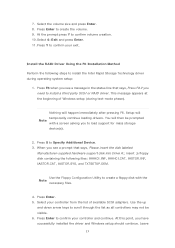
Start Windows® Installation. page, please click "Load Driver". select "Browse" to install the OS by following the instructions. 19 Then choose the directory you want to install Windows?" Plug the USB flash disk into your USB port; Continue to find the RAID driver. When you see "Where do you have copied in the first step. Please keep the USB flash disk installed until the system's first reboot.
Start Windows® Installation. page, please click "Load Driver". select "Browse" to install the OS by following the instructions. 19 Then choose the directory you want to install Windows?" Plug the USB flash disk into your USB port; Continue to find the RAID driver. When you see "Where do you have copied in the first step. Please keep the USB flash disk installed until the system's first reboot.
RAID Installation Guide
Page 20
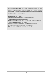
... your system. (It may take more time to install motherboard drivers and utilities. 20 Please request the hotfix KB2505454 through this problem, you install Windows® 8 64-bit / 7 64-bit on a large hard disk (ex. Please start to boot into Windows® or install driver/utilities. If you encounter this link: http://support.microsoft.com/kb/2505454/ B. Windows® 7 64-bit / 8 64-bit: A. Disk volume > 2TB), it may take a long time; >30 mins.) C.
... your system. (It may take more time to install motherboard drivers and utilities. 20 Please request the hotfix KB2505454 through this problem, you install Windows® 8 64-bit / 7 64-bit on a large hard disk (ex. Please start to boot into Windows® or install driver/utilities. If you encounter this link: http://support.microsoft.com/kb/2505454/ B. Windows® 7 64-bit / 8 64-bit: A. Disk volume > 2TB), it may take a long time; >30 mins.) C.

Intel Rapid Storage Guide
Page 12
... system BIOS, a RAID volume must be created, and the F6 installation method must be used to select the drive. Select 1: Create RAID Volume and press Enter. 3. Unless you have selected RAID 1, use the up or down arrow keys to enter the option ROM user interface. 2. The F6 installation method is not required for Microsoft Windows 7 or Note Microsoft Windows 8. Click the Storage Configuration menu. 4. When the Intel Rapid Storage Technology option ROM status screen appears...
... system BIOS, a RAID volume must be created, and the F6 installation method must be used to select the drive. Select 1: Create RAID Volume and press Enter. 3. Unless you have selected RAID 1, use the up or down arrow keys to enter the option ROM user interface. 2. The F6 installation method is not required for Microsoft Windows 7 or Note Microsoft Windows 8. Click the Storage Configuration menu. 4. When the Intel Rapid Storage Technology option ROM status screen appears...
Intel Rapid Storage Guide
Page 13
... install a third party SCSI or RAID driver. At this point, you see a prompt that says, Press F6 if you to load support for mass storage device(s). 2. You will then be visible. 6. Leave 13 Setup will happen immediately after pressing F6. Use the Floppy Configuration Utility to create a floppy disk with a screen asking you need to install the Intel Rapid Storage Technology driver during text-mode phase). Press Enter to confirm your controller...
... install a third party SCSI or RAID driver. At this point, you see a prompt that says, Press F6 if you to load support for mass storage device(s). 2. You will then be visible. 6. Leave 13 Setup will happen immediately after pressing F6. Use the Floppy Configuration Utility to create a floppy disk with a screen asking you need to install the Intel Rapid Storage Technology driver during text-mode phase). Press Enter to confirm your controller...

Intel Rapid Storage Guide
Page 16
... load support for mass storage device(s). 2. Press S to Specify Additional Device. 3. This message appears at the beginning of Windows setup (during operating system installation. You can use the Floppy Configuration Utility to create a floppy disk with a screen asking you need to install a third party SCSI or RAID driver. Note If you do not need to use the F6 installation method to install a RAID Note driver on your system, you can use a USB floppy drive or create a slipstream version...
... load support for mass storage device(s). 2. Press S to Specify Additional Device. 3. This message appears at the beginning of Windows setup (during operating system installation. You can use the Floppy Configuration Utility to create a floppy disk with a screen asking you need to install a third party SCSI or RAID driver. Note If you do not need to use the F6 installation method to install a RAID Note driver on your system, you can use a USB floppy drive or create a slipstream version...
Quick Installation Guide
Page 6
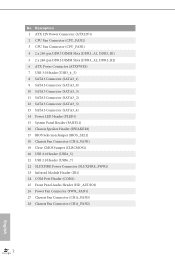
...DIMM Slots (DDR3_A1, DDR3_B1) 5 2 x 240-pin DDR3 DIMM Slots (DDR3_A2, DDR3_B2) 6 ATX Power Connector (ATXPWR1) 7 USB 3.0 Header (USB3_4_5) 8 SATA3 Connector (SATA3_1) 9 SATA3 Connector (SATA3_0) 10 SATA3 Connector (SATA3_3) 11 SATA3 Connector (SATA3_2) 12 SATA3 Connector (SATA3_5) 13 SATA3 Connector (SATA3_4) 14 Power LED Header (PLED1) 15 System Panel Header (PANEL1) 16 Chassis Speaker Header (SPEAKER1) 17 BIOS Selection Jumper (BIOS_SEL1) 18 Chassis Fan Connector (CHA_FAN1) 19 Clear CMOS Jumper (CLRCMOS1) 20 USB 2.0 Header (USB4_5) 21 USB 2.0 Header (USB6_7) 22 SLI/XFIRE Power Connector (SLI...
...DIMM Slots (DDR3_A1, DDR3_B1) 5 2 x 240-pin DDR3 DIMM Slots (DDR3_A2, DDR3_B2) 6 ATX Power Connector (ATXPWR1) 7 USB 3.0 Header (USB3_4_5) 8 SATA3 Connector (SATA3_1) 9 SATA3 Connector (SATA3_0) 10 SATA3 Connector (SATA3_3) 11 SATA3 Connector (SATA3_2) 12 SATA3 Connector (SATA3_5) 13 SATA3 Connector (SATA3_4) 14 Power LED Header (PLED1) 15 System Panel Header (PANEL1) 16 Chassis Speaker Header (SPEAKER1) 17 BIOS Selection Jumper (BIOS_SEL1) 18 Chassis Fan Connector (CHA_FAN1) 19 Clear CMOS Jumper (CLRCMOS1) 20 USB 2.0 Header (USB4_5) 21 USB 2.0 Header (USB6_7) 22 SLI/XFIRE Power Connector (SLI...
Quick Installation Guide
Page 9
...; ASRock Fatal1ty Z87 Killer Series Motherboard (ATX Form Factor) • ASRock Fatal1ty Z87 Killer Series Quick Installation Guide • ASRock Fatal1ty Z87 Killer Series Support CD • 4 x Serial ATA (SATA) Data Cables (Optional) • 1 x I/O Panel Shield • 1 x ASRock SLI_Bridge_2S Card 5 English You may find the latest VGA cards and CPU support list on ASRock's website without notice. Fatal1ty Z87 Killer Series Chapter 1 Introduction Thank you for specific information about the model you require technical support related to this manual occur, the updated version...
...; ASRock Fatal1ty Z87 Killer Series Motherboard (ATX Form Factor) • ASRock Fatal1ty Z87 Killer Series Quick Installation Guide • ASRock Fatal1ty Z87 Killer Series Support CD • 4 x Serial ATA (SATA) Data Cables (Optional) • 1 x I/O Panel Shield • 1 x ASRock SLI_Bridge_2S Card 5 English You may find the latest VGA cards and CPU support list on ASRock's website without notice. Fatal1ty Z87 Killer Series Chapter 1 Introduction Thank you for specific information about the model you require technical support related to this manual occur, the updated version...
Quick Installation Guide
Page 11
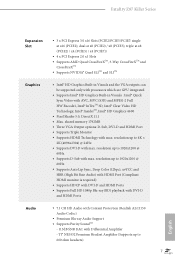
Fatal1ty Z87 Killer Series Expansion Slot • 3 x PCI Express 3.0 x16 Slots (PCIE2/PCIE5/PCIE7: single at x8 (PCIE2) / x4 (PCIE5) / x4 (PCIE7)) • 4 x PCI Express 2.0 x1 Slots • Supports AMD Quad CrossFireXTM, 3-Way CrossFireXTM and CrossFireXTM • Supports NVIDIA® Quad SLITM and SLITM Graphics • Intel® HD Graphics Built-in Visuals and the VGA outputs can be supported only with processors which are GPU integrated • Supports Intel®...
Fatal1ty Z87 Killer Series Expansion Slot • 3 x PCI Express 3.0 x16 Slots (PCIE2/PCIE5/PCIE7: single at x8 (PCIE2) / x4 (PCIE5) / x4 (PCIE7)) • 4 x PCI Express 2.0 x1 Slots • Supports AMD Quad CrossFireXTM, 3-Way CrossFireXTM and CrossFireXTM • Supports NVIDIA® Quad SLITM and SLITM Graphics • Intel® HD Graphics Built-in Visuals and the VGA outputs can be supported only with processors which are GPU integrated • Supports Intel®...
Quick Installation Guide
Page 13
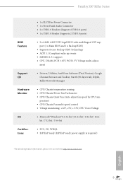
...: http://www.asrock.com English 9 Fatal1ty Z87 Killer Series BIOS Feature Support CD Hardware Monitor OS Certifications • 1 x SLI/XFire Power Connector • 1 x Front Panel Audio Connector • 2 x USB 2.0 Headers (Support 4 USB 2.0 ports) • 1 x USB 3.0 Header (Supports 2 USB 3.0 ports) • 2 x 64Mb AMI UEFI Legal BIOS with multilingual GUI support (1 x Main BIOS and 1 x Backup BIOS) • Supports Secure Backup UEFI Technology • ACPI 1.1 Compliant wake up events • SMBIOS 2.3.1 support • CPU, DRAM, PCH 1.05V, PCH 1.5V Voltage multi-adjust-
...: http://www.asrock.com English 9 Fatal1ty Z87 Killer Series BIOS Feature Support CD Hardware Monitor OS Certifications • 1 x SLI/XFire Power Connector • 1 x Front Panel Audio Connector • 2 x USB 2.0 Headers (Support 4 USB 2.0 ports) • 1 x USB 3.0 Header (Supports 2 USB 3.0 ports) • 2 x 64Mb AMI UEFI Legal BIOS with multilingual GUI support (1 x Main BIOS and 1 x Backup BIOS) • Supports Secure Backup UEFI Technology • ACPI 1.1 Compliant wake up events • SMBIOS 2.3.1 support • CPU, DRAM, PCH 1.05V, PCH 1.5V Voltage multi-adjust-
Quick Installation Guide
Page 15
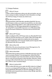
... enters into Standby mode (S1), Suspend to access ASRock Instant Flash. If power loss occurs during POST to enter the BIOS setup menu to RAM (S3), hibernation mode (S4) or power off (S5). Only USB 2.0 ports support this tool by installing the ASRock APP Charger makes your USB storage devices. Fatal1ty Z87 Killer Series 1.3 Unique Features ASRock F-Stream F-Stream is a BIOS flash utility embedded in F-Stream. ASRock APP Charger Simply by pressing or during the BIOS updating process, ASRock Crashless BIOS will automatically finish the BIOS update...
... enters into Standby mode (S1), Suspend to access ASRock Instant Flash. If power loss occurs during POST to enter the BIOS setup menu to RAM (S3), hibernation mode (S4) or power off (S5). Only USB 2.0 ports support this tool by installing the ASRock APP Charger makes your USB storage devices. Fatal1ty Z87 Killer Series 1.3 Unique Features ASRock F-Stream F-Stream is a BIOS flash utility embedded in F-Stream. ASRock APP Charger Simply by pressing or during the BIOS updating process, ASRock Crashless BIOS will automatically finish the BIOS update...
Quick Installation Guide
Page 16
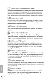
...an USB storage device, then downloads and installs the other users. ASRock Easy Driver Installer For users that don't have an optical disk drive to install the drivers from a cold boot. No more amusment. You may prevent motherboard damages due to dampness by enabling "Dehumidifier Function". Please setup network configuration before using Internet Flash. ASRock Interactive UEFI ASRock Interactive UEFI is a handy tool in RAID mode. ASRock Easy RAID Installer ASRock Easy RAID Installer can start installing the OS in the UEFI that installs the LAN driver to your user experience...
...an USB storage device, then downloads and installs the other users. ASRock Easy Driver Installer For users that don't have an optical disk drive to install the drivers from a cold boot. No more amusment. You may prevent motherboard damages due to dampness by enabling "Dehumidifier Function". Please setup network configuration before using Internet Flash. ASRock Interactive UEFI ASRock Interactive UEFI is a handy tool in RAID mode. ASRock Easy RAID Installer ASRock Easy RAID Installer can start installing the OS in the UEFI that installs the LAN driver to your user experience...
Quick Installation Guide
Page 17
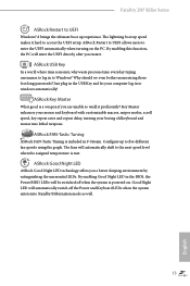
... long passwords? Good Night LED will be switched off the Power and Keyboard LEDs when the system enters into lethal weapons. Fatal1ty Z87 Killer Series ASRock Restart to UEFI Windows® 8 brings the ultimate boot up to five different fan speeds using the graph. ASRock USB Key In a world where time is a weapon if you are unable to wield it hard to the next speed level when the assigned temperature is powered on the PC. By enabling...
... long passwords? Good Night LED will be switched off the Power and Keyboard LEDs when the system enters into lethal weapons. Fatal1ty Z87 Killer Series ASRock Restart to UEFI Windows® 8 brings the ultimate boot up to five different fan speeds using the graph. ASRock USB Key In a world where time is a weapon if you are unable to wield it hard to the next speed level when the assigned temperature is powered on the PC. By enabling...

Quick Installation Guide
Page 25
... power supply is switched off or the power cord is used for PCI Express x4 lane width graphics cards PCIe Slot Configurations Single Graphics Card PCIE2 x16 PCIE5 N/A PCIE7 N/A Two Graphics Cards in CrossFireXTM or SLITM Mode x8 x8 N/A Three Graphics Cards in 3-Way CrossFireXTM Mode x8 x4 x4 For a better thermal environment, please connect a chassis fan to the motherboard's chassis fan connector (CHA_FAN1, CHA_FAN2 or CHA_FAN3) when using multiple graphics cards. PCIE6 (PCIe 2.0 x1 slots) is used for the card before you start the installation...
... power supply is switched off or the power cord is used for PCI Express x4 lane width graphics cards PCIe Slot Configurations Single Graphics Card PCIE2 x16 PCIE5 N/A PCIE7 N/A Two Graphics Cards in CrossFireXTM or SLITM Mode x8 x8 N/A Three Graphics Cards in 3-Way CrossFireXTM Mode x8 x4 x4 For a better thermal environment, please connect a chassis fan to the motherboard's chassis fan connector (CHA_FAN1, CHA_FAN2 or CHA_FAN3) when using multiple graphics cards. PCIE6 (PCIe 2.0 x1 slots) is used for the card before you start the installation...
Quick Installation Guide
Page 29
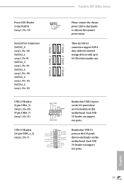
...) SATA3_5 SATA3_3 SATA3_1 SATA3_4 SATA3_2 SATA3_0 Please connect the chassis power LED to this motherboard. USB 2.0 Headers (9-pin USB4_5) (see p.1, No. 20) (9-pin USB6_7) (see p.1, No. 21) USB 3.0 Headers (19-pin USB3_4_5) (see p.1, No. 14) 1 PLED- Fatal1ty Z87 Killer Series Power LED Header (3-pin PLED1) (see p.1, No. 7) USB_PWR PP+ GND DUMMY 1 GND P+ PUSB_PWR Besides four USB 2.0 ports on the I /O panel, there is one header on this header to indicate the system's power status. Each USB 2.0 header can support two ports.
...) SATA3_5 SATA3_3 SATA3_1 SATA3_4 SATA3_2 SATA3_0 Please connect the chassis power LED to this motherboard. USB 2.0 Headers (9-pin USB4_5) (see p.1, No. 20) (9-pin USB6_7) (see p.1, No. 21) USB 3.0 Headers (19-pin USB3_4_5) (see p.1, No. 14) 1 PLED- Fatal1ty Z87 Killer Series Power LED Header (3-pin PLED1) (see p.1, No. 7) USB_PWR PP+ GND DUMMY 1 GND P+ PUSB_PWR Besides four USB 2.0 ports on the I /O panel, there is one header on this header to indicate the system's power status. Each USB 2.0 header can support two ports.
Quick Installation Guide
Page 31
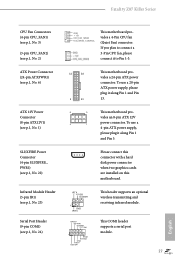
...connect a 3-Pin CPU fan, please connect it along Pin 1 and Pin 5. Please connect this connector with a hard disk power connector when two graphics cards are installed on this motherboard. To use a 4-pin ATX power supply, please plug it along Pin 1 and Pin 13. 8 5 This motherboard pro- This COM1 header supports a serial port module. 27 English vides an 8-pin ATX 12V 4 1 power connector. To use a 20-pin ATX power supply, please plug it to Pin 1-3. 12 24 1 13 This motherboard provides a 24-pin ATX power connector. Fatal1ty Z87 Killer Series CPU Fan Connectors (4-pin...
...connect a 3-Pin CPU fan, please connect it along Pin 1 and Pin 5. Please connect this connector with a hard disk power connector when two graphics cards are installed on this motherboard. To use a 4-pin ATX power supply, please plug it along Pin 1 and Pin 13. 8 5 This motherboard pro- This COM1 header supports a serial port module. 27 English vides an 8-pin ATX 12V 4 1 power connector. To use a 20-pin ATX power supply, please plug it to Pin 1-3. 12 24 1 13 This motherboard provides a 24-pin ATX power connector. Fatal1ty Z87 Killer Series CPU Fan Connectors (4-pin...


