
User Manual
Page 6
... Specifications 2 1.3 Motherboard Layout 7 1.4 I/O Panel 10 Chapter 2 Installation 12 2.1 Installing the CPU 13 2.2 Installing the CPU Fan and Heatsink 16 2.3 Installation of Memory Modules (DIMM) 17 2.4 Expansion Slots (PCI Express Slots) 19 2.5 Jumpers Setup 21 2.6 Onboard Headers and Connectors 22 2.7 Smart Switches 28 2.8 Dr. Debug 31 2.9 Post Status Checker 33 2.10 SLITM , 3-Way SLITM , 4-Way SLITM and Quad SLITM Operation Guide34 2.10.1 Installing Two SLITM-Ready Graphics Cards 34 2.10.2 Installing Three SLITM-Ready Graphics Cards 36 2.10.3 Installing Four...
... Specifications 2 1.3 Motherboard Layout 7 1.4 I/O Panel 10 Chapter 2 Installation 12 2.1 Installing the CPU 13 2.2 Installing the CPU Fan and Heatsink 16 2.3 Installation of Memory Modules (DIMM) 17 2.4 Expansion Slots (PCI Express Slots) 19 2.5 Jumpers Setup 21 2.6 Onboard Headers and Connectors 22 2.7 Smart Switches 28 2.8 Dr. Debug 31 2.9 Post Status Checker 33 2.10 SLITM , 3-Way SLITM , 4-Way SLITM and Quad SLITM Operation Guide34 2.10.1 Installing Two SLITM-Ready Graphics Cards 34 2.10.2 Installing Three SLITM-Ready Graphics Cards 36 2.10.3 Installing Four...
User Manual
Page 9
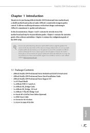
...; 1 x I/O Panel Shield • 1 x ASRock USB 3.1 Card/A+A • 2 x ASRock SLI_Bridge Cards • 1 x ASRock SLI_Bridge_3S Card • 1 x ASRock 3-Way SLI Bridge Card • 6 x Serial ATA (SATA) Data Cables (Optional) • 1 x HDD Saver Cable • 2 x Screws for M.2 Sockets • 1 x Screw for purchasing ASRock Fatal1ty X99 Professional Series motherboard, a reliable motherboard produced under ASRock's consistently stringent quality control. If you require technical support related to quality and endurance. Chapter 4 contains the configuration guide of the BIOS setup.
...; 1 x I/O Panel Shield • 1 x ASRock USB 3.1 Card/A+A • 2 x ASRock SLI_Bridge Cards • 1 x ASRock SLI_Bridge_3S Card • 1 x ASRock 3-Way SLI Bridge Card • 6 x Serial ATA (SATA) Data Cables (Optional) • 1 x HDD Saver Cable • 2 x Screws for M.2 Sockets • 1 x Screw for purchasing ASRock Fatal1ty X99 Professional Series motherboard, a reliable motherboard produced under ASRock's consistently stringent quality control. If you require technical support related to quality and endurance. Chapter 4 contains the configuration guide of the BIOS setup.
User Manual
Page 11
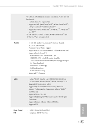
...; Supports Lightning/ESD Protection (ASRock Full Spike Protection) • Supports Energy Efficient Ethernet 802.3az • Supports PXE Rear Panel I/O • 1 x PS/2 Mouse/Keyboard Port • 1 x Optical SPDIF Out Port 3 English Nichicon Fine Gold Series Audio Caps - 115dB SNR DAC with 28 lanes, 4-Way CrossFireXTM and 4-Way SLITM are not supported. Fatal1ty X99 Professional/3.1 Series * If Ultra M.2 PCI Express module is installed, PCIE3 slot will be disabled. • 1 x Half Mini-PCI Express Slot • Supports AMD...
...; Supports Lightning/ESD Protection (ASRock Full Spike Protection) • Supports Energy Efficient Ethernet 802.3az • Supports PXE Rear Panel I/O • 1 x PS/2 Mouse/Keyboard Port • 1 x Optical SPDIF Out Port 3 English Nichicon Fine Gold Series Audio Caps - 115dB SNR DAC with 28 lanes, 4-Way CrossFireXTM and 4-Way SLITM are not supported. Fatal1ty X99 Professional/3.1 Series * If Ultra M.2 PCI Express module is installed, PCIE3 slot will be disabled. • 1 x Half Mini-PCI Express Slot • Supports AMD...
User Manual
Page 12
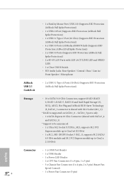
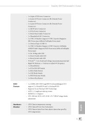
... LAN Ports with LED (ACT/LINK LED and SPEED LED) • 1 x Clear CMOS Switch • HD Audio Jacks: Rear Speaker / Central / Bass / Line in / Front Speaker / Microphone ASRock USB 3.1 Card/A+A • 2 x USB 3.1 Type-A Ports (10 Gb/s) (Supports ESD Protection (ASRock Full Spike Protection)) Storage • 10 x SATA3 6.0 Gb/s Connectors, support RAID (RAID 0, RAID 1, RAID 5, RAID 10 and Intel Rapid Storage 13), NCQ, AHCI, Hot Plug and ASRock HDD Saver Technology (S_SATA3_3 connector is shared with M.2 Socket (M2_1)) * RAID is supported on SATA3_0 ~ SATA3_5 ports only. • 1 x SATA...
... LAN Ports with LED (ACT/LINK LED and SPEED LED) • 1 x Clear CMOS Switch • HD Audio Jacks: Rear Speaker / Central / Bass / Line in / Front Speaker / Microphone ASRock USB 3.1 Card/A+A • 2 x USB 3.1 Type-A Ports (10 Gb/s) (Supports ESD Protection (ASRock Full Spike Protection)) Storage • 10 x SATA3 6.0 Gb/s Connectors, support RAID (RAID 0, RAID 1, RAID 5, RAID 10 and Intel Rapid Storage 13), NCQ, AHCI, Hot Plug and ASRock HDD Saver Technology (S_SATA3_3 connector is shared with M.2 Socket (M2_1)) * RAID is supported on SATA3_0 ~ SATA3_5 ports only. • 1 x SATA...
User Manual
Page 13
... 128Mb AMI UEFI Legal BIOS with LED • V-ProbeTM: 7-set of onboard voltage measurement points laid • Rapid OC Buttons: +/- Fatal1ty X99 Professional/3.1 Series BIOS Feature Hardware Monitor • 1 x 24 pin ATX Power Connector • 1 x 8 pin 12V Power Connector (Hi-Density Power Connector) • 1 x 4 pin 12V Power Connector (Hi-Density Power Connector) • 1 x HDD Saver Connector • 1 x PCIe Power Connector • 1 x Front Panel Audio Connector • 1 x Thunderbolt AIC Connector • 2 x USB 2.0 Headers (support 4 USB 2.0 ports) (Supports ESD Protection...
... 128Mb AMI UEFI Legal BIOS with LED • V-ProbeTM: 7-set of onboard voltage measurement points laid • Rapid OC Buttons: +/- Fatal1ty X99 Professional/3.1 Series BIOS Feature Hardware Monitor • 1 x 24 pin ATX Power Connector • 1 x 8 pin 12V Power Connector (Hi-Density Power Connector) • 1 x 4 pin 12V Power Connector (Hi-Density Power Connector) • 1 x HDD Saver Connector • 1 x PCIe Power Connector • 1 x Front Panel Audio Connector • 1 x Thunderbolt AIC Connector • 2 x USB 2.0 Headers (support 4 USB 2.0 ports) (Supports ESD Protection...
User Manual
Page 16
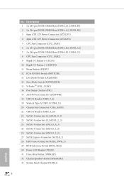
...) 16 Post Status Checker (PSC) 17 ATX Power Connector (ATXPWR1) 18 USB 3.0 Header (USB3_7_8) 19 Vertical Type A USB 3.0 (USB3_11) 20 Chassis Fan Connector (CHA_FAN3) 21 USB 3.0 Header (USB3_9_10) 22 SATA3 Connectors (S_SATA3_0_1) 23 SATA3 Connectors (S_SATA3_2_3) 24 SATA3 Connectors (SATA3_0_3) 25 SATA3 Connectors (SATA3_1_4) 26 SATA3 Connectors (SATA3_2_5) 27 SATA Express Connector (SATAE_1) 28 HDD Saver Connector (SATA_PWR_1) 29 BIOS Selection Switch (BIOS_SEL1) 30 Power LED Header (PLED1) 31 Direct Key Button (DIRKEY1) 32 Chassis Speaker Header (SPEAKER1) 33 System Panel Header (PANEL1...
...) 16 Post Status Checker (PSC) 17 ATX Power Connector (ATXPWR1) 18 USB 3.0 Header (USB3_7_8) 19 Vertical Type A USB 3.0 (USB3_11) 20 Chassis Fan Connector (CHA_FAN3) 21 USB 3.0 Header (USB3_9_10) 22 SATA3 Connectors (S_SATA3_0_1) 23 SATA3 Connectors (S_SATA3_2_3) 24 SATA3 Connectors (SATA3_0_3) 25 SATA3 Connectors (SATA3_1_4) 26 SATA3 Connectors (SATA3_2_5) 27 SATA Express Connector (SATAE_1) 28 HDD Saver Connector (SATA_PWR_1) 29 BIOS Selection Switch (BIOS_SEL1) 30 Power LED Header (PLED1) 31 Direct Key Button (DIRKEY1) 32 Chassis Speaker Header (SPEAKER1) 33 System Panel Header (PANEL1...
User Manual
Page 27
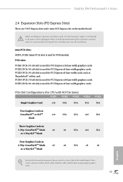
... switched off or the power cord is used for the card before you start the installation. PCIe slots: PCIE1 (PCIe 3.0 x16 slot) is unplugged. PCIE5 (PCIe 3.0 x16 slot) is used for PCI Express x16 lane width graphics cards. PCIE3 (PCIe 3.0 x16 slot) is used for PCI Express x8 lane width cards, such as Thunderbolt™ add-in 4-Way CrossFireXTM Mode x8 x8 N/A x8 x8 or 4-Way SLITM Mode For a better thermal environment, please connect a chassis fan to the motherboard's chassis fan connector...
... switched off or the power cord is used for the card before you start the installation. PCIe slots: PCIE1 (PCIe 3.0 x16 slot) is unplugged. PCIE5 (PCIe 3.0 x16 slot) is used for PCI Express x16 lane width graphics cards. PCIE3 (PCIe 3.0 x16 slot) is used for PCI Express x8 lane width cards, such as Thunderbolt™ add-in 4-Way CrossFireXTM Mode x8 x8 N/A x8 x8 or 4-Way SLITM Mode For a better thermal environment, please connect a chassis fan to the motherboard's chassis fan connector...
User Manual
Page 34
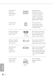
... 4) PCIe Power Connector (4-pin PCIE_PWR1) (see p.7, No. 43) HDD Saver Connector (4-pin SATA_PWR_1) (see p.7, No. 28) Thunderbolt AIC Connector (5-pin TBT1) (see p.7, No. 44) Serial Port Header (9-pin COM1) (see p.7, No. 42) 8 5 This motherboard provides an 8-pin ATX 12V power connector and 4 1 a 4-pin ATX 12V power connector. RRXD1 DDTR#1 DDSR#1 CCTS#1 1 RRI#1 RRTS#1 GND TTXD1 DDCD#1 This COM1 header supports a serial port module. GND +12V DETECT Please connect a 4 pin molex power cable to this connector when more than three PCI Express cards are installed. 1 Please connect...
... 4) PCIe Power Connector (4-pin PCIE_PWR1) (see p.7, No. 43) HDD Saver Connector (4-pin SATA_PWR_1) (see p.7, No. 28) Thunderbolt AIC Connector (5-pin TBT1) (see p.7, No. 44) Serial Port Header (9-pin COM1) (see p.7, No. 42) 8 5 This motherboard provides an 8-pin ATX 12V power connector and 4 1 a 4-pin ATX 12V power connector. RRXD1 DDTR#1 DDSR#1 CCTS#1 1 RRI#1 RRTS#1 GND TTXD1 DDCD#1 This COM1 header supports a serial port module. GND +12V DETECT Please connect a 4 pin molex power cable to this connector when more than three PCI Express cards are installed. 1 Please connect...

User Manual
Page 37
... use "Secure Backup UEFI" in the UEFI Setup Utility to duplicate a working copy of your PCIE card could be burnt if it from either BIOS A or BIOS B. For safety issues, users are not able to ensure normal system operation. When you to enable and disable the corresponding PCIE x16 slots. Fatal1ty X99 Professional/3.1 Series PCIe ON/OFF Switch (PCIE_SWITCH) (see p.7, No. 29) AB BIOS Selection Switch allows the system to boot from the motherboard. This motherboard...
... use "Secure Backup UEFI" in the UEFI Setup Utility to duplicate a working copy of your PCIE card could be burnt if it from either BIOS A or BIOS B. For safety issues, users are not able to ensure normal system operation. When you to enable and disable the corresponding PCIE x16 slots. Fatal1ty X99 Professional/3.1 Series PCIe ON/OFF Switch (PCIE_SWITCH) (see p.7, No. 29) AB BIOS Selection Switch allows the system to boot from the motherboard. This motherboard...
User Manual
Page 39
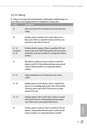
... memory and VGA card, and remove other memory modules. Please re-install the memory and CPU. Code Description 00 Please check if the CPU is used to provide code information, which makes troubleshooting even easier. If the problem still exists, please install only one memory module or try using other devices. If the problem still exists, please clear CMOS and try removing all PCI-E devices or try using other slots. If the problem still exists, please remove all SATA devices. Fatal1ty X99 Professional/3.1 Series...
... memory and VGA card, and remove other memory modules. Please re-install the memory and CPU. Code Description 00 Please check if the CPU is used to provide code information, which makes troubleshooting even easier. If the problem still exists, please install only one memory module or try using other devices. If the problem still exists, please clear CMOS and try removing all PCI-E devices or try using other slots. If the problem still exists, please remove all SATA devices. Fatal1ty X99 Professional/3.1 Series...
User Manual
Page 49
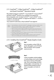
... PCI Express x16 graphics cards. Fatal1ty X99 Professional/3.1 Series 2.11 CrossFireXTM, 3-Way CrossFireXTM , 4-Way CrossFireXTM and Quad CrossFireXTM Operation Guide This motherboard supports CrossFireXTM, 3-way CrossFireXTM, 4-way CrossFireXTM and Quad CrossFireXTM that allows you purchase, not bundled with a 16-pipe card, both cards will operate as 12-pipe cards while in CrossFireXTM mode. 5. Make sure that your graphics card driver supports AMD CrossFireXTM technology. Please refer to AMD graphics card manuals for detailed installation guide. 2.11.1 Installing...
... PCI Express x16 graphics cards. Fatal1ty X99 Professional/3.1 Series 2.11 CrossFireXTM, 3-Way CrossFireXTM , 4-Way CrossFireXTM and Quad CrossFireXTM Operation Guide This motherboard supports CrossFireXTM, 3-way CrossFireXTM, 4-way CrossFireXTM and Quad CrossFireXTM that allows you purchase, not bundled with a 16-pipe card, both cards will operate as 12-pipe cards while in CrossFireXTM mode. 5. Make sure that your graphics card driver supports AMD CrossFireXTM technology. Please refer to AMD graphics card manuals for detailed installation guide. 2.11.1 Installing...
User Manual
Page 52
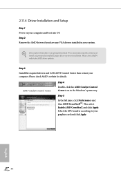
... boot into OS. Step 2 Remove the AMD drivers if you have any previously installed Catalyst drivers prior to installation. Please check AMD's website for AMD driver updates. AMD Catalyst Control Center Step 4 Double-click the AMD Catalyst Control Center icon in your graphics card and click Apply. We recommend using this utility to your system. The Catalyst Uninstaller is an optional download. Please check AMD's website for details. English 44 2.11.4 Driver Installation and Setup...
... boot into OS. Step 2 Remove the AMD drivers if you have any previously installed Catalyst drivers prior to installation. Please check AMD's website for AMD driver updates. AMD Catalyst Control Center Step 4 Double-click the AMD Catalyst Control Center icon in your graphics card and click Apply. We recommend using this utility to your system. The Catalyst Uninstaller is an optional download. Please check AMD's website for details. English 44 2.11.4 Driver Installation and Setup...
User Manual
Page 59
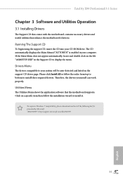
... automatically, locate and double click on a specific item then follow the order from top to bottom to display the menu. Utilities Menu The Utilities Menu shows the application software that enhance the motherboard's features. Therefore, the drivers you install can work properly. Drivers Menu The drivers compatible to install it. The CD automatically displays the Main Menu if "AUTORUN" is enabled in the Support CD to install those required drivers. Fatal1ty X99 Professional/3.1 Series Chapter 3 Software and Utilities Operation 3.1 Installing Drivers The Support CD...
... automatically, locate and double click on a specific item then follow the order from top to bottom to display the menu. Utilities Menu The Utilities Menu shows the application software that enhance the motherboard's features. Therefore, the drivers you install can work properly. Drivers Menu The drivers compatible to install it. The CD automatically displays the Main Menu if "AUTORUN" is enabled in the Support CD to install those required drivers. Fatal1ty X99 Professional/3.1 Series Chapter 3 Software and Utilities Operation 3.1 Installing Drivers The Support CD...

User Manual
Page 65
Fatal1ty X99 Professional/3.1 Series Tech Service Contact Tech Service if you start up the Windows operating system. 57 English Click to select "Auto run at Windows Startup" if you want F-Stream to be launched when you have problems with your contact information along with details of the problem. Settings Configure ASRock F-Stream. Please leave your computer.
Fatal1ty X99 Professional/3.1 Series Tech Service Contact Tech Service if you start up the Windows operating system. 57 English Click to select "Auto run at Windows Startup" if you want F-Stream to be launched when you have problems with your contact information along with details of the problem. Settings Configure ASRock F-Stream. Please leave your computer.

User Manual
Page 105
Serial Port Address Select the address of the Serial port. PS2 Y-Cable Enable the PS2 Y-Cable or set this option to Auto. 97 English 4.4.4 Super IO Configuration Fatal1ty X99 Professional/3.1 Series Serial Port Enable or disable the Serial port.
Serial Port Address Select the address of the Serial port. PS2 Y-Cable Enable the PS2 Y-Cable or set this option to Auto. 97 English 4.4.4 Super IO Configuration Fatal1ty X99 Professional/3.1 Series Serial Port Enable or disable the Serial port.
User Manual
Page 107
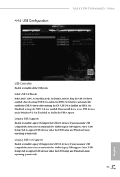
...USB Configuration Fatal1ty X99 Professional/3.1 Series USB Controller Enable or disable all the USB ports. Legacy USB Support Enable or disable Legacy OS Support for USB 3.0 devices. Intel USB 3.0 Mode Select Intel® USB 3.0 controller mode. Set [Enabled] to keep the USB 3.0 driver enabled after entering the OS (USB 3.0 is enabled in BIOS). Set [Disabled] to support USB devices under the UEFI setup and Windows/Linux operating systems only. 99 English Legacy USB 3.0 Support Enable or disable Legacy OS Support for USB 2.0 devices. If you encounter USB compatibility...
...USB Configuration Fatal1ty X99 Professional/3.1 Series USB Controller Enable or disable all the USB ports. Legacy USB Support Enable or disable Legacy OS Support for USB 3.0 devices. Intel USB 3.0 Mode Select Intel® USB 3.0 controller mode. Set [Enabled] to keep the USB 3.0 driver enabled after entering the OS (USB 3.0 is enabled in BIOS). Set [Disabled] to support USB devices under the UEFI setup and Windows/Linux operating systems only. 99 English Legacy USB 3.0 Support Enable or disable Legacy OS Support for USB 2.0 devices. If you encounter USB compatibility...
User Manual
Page 111
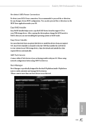
... SATA mode to use this tool. 103 English Please setup network configuration before using UEFI Tech Service. Boot Manager Boot Manager is specifically designed for any changes of your HDD configuration. Easy RAID Installer Easy RAID Installer helps you are having trouble with your USB storage device. UEFI Tech Service Contact ASRock Tech Service if you to copy the RAID driver from our support CD, Easy Driver Installer is recommended to proceed the re-detection for the dual OS platform/multi-OS platform users...
... SATA mode to use this tool. 103 English Please setup network configuration before using UEFI Tech Service. Boot Manager Boot Manager is specifically designed for any changes of your HDD configuration. Easy RAID Installer Easy RAID Installer helps you are having trouble with your USB storage device. UEFI Tech Service Contact ASRock Tech Service if you to copy the RAID driver from our support CD, Easy Driver Installer is recommended to proceed the re-detection for the dual OS platform/multi-OS platform users...
User Manual
Page 112
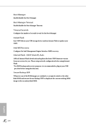
Please setup network configuration before using Internet Flash. *For BIOS backup and recovery purpose, it is recommended to plug in your USB storage device and run Instant Flash to update your USB pen drive before using this function. DHCP (Auto IP), Auto ASRock Internet Flash downloads and updates the latest UEFI firmware version from our servers for the Boot Manager. Internet Flash - Timeout Seconds Configure the number of the ROM images are outdated or corrupted, switch to the other flash ROM and execute...
Please setup network configuration before using Internet Flash. *For BIOS backup and recovery purpose, it is recommended to plug in your USB storage device and run Instant Flash to update your USB pen drive before using this function. DHCP (Auto IP), Auto ASRock Internet Flash downloads and updates the latest UEFI firmware version from our servers for the Boot Manager. Internet Flash - Timeout Seconds Configure the number of the ROM images are outdated or corrupted, switch to the other flash ROM and execute...
User Manual
Page 113
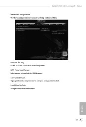
Save User Default Type a profile name and press enter to download the UEFI firmware. Load User Default Load previously saved user defaults. 105 English Internet Setting Enable or disable sound effects in the setup utility. UEFI Download Server Select a server to save your settings as user default. Fatal1ty X99 Professional/3.1 Series Network Configuration Use this to configure internet connection settings for Internet Flash.
Save User Default Type a profile name and press enter to download the UEFI firmware. Load User Default Load previously saved user defaults. 105 English Internet Setting Enable or disable sound effects in the setup utility. UEFI Download Server Select a server to save your settings as user default. Fatal1ty X99 Professional/3.1 Series Network Configuration Use this to configure internet connection settings for Internet Flash.
RAID Installation Guide
Page 7
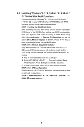
... key to enter BIOS setup utility. A. Press [Enter] to complete the process. Follow the onscreen instruction to conirm the selection. STEP 4: Install Windows® 8.1 / 8.1 64-bit / 8 / 8 64-bit / 7 / 7 64-bit OS on your change before setting your USB storage device with RAID functions, please follow the procedures below. Enter UEFI SETUP UTILITY Tool and highlight "Easy RAID Installer". Press key to save your system. 7 Plug in UEFI setup. Boot your USB lash drive into a USB port. 2.3 Installing Windows® 8.1 / 8.1 64-bit / 8 / 8 64-bit / 7 / 7 64-bit With RAID...
... key to enter BIOS setup utility. A. Press [Enter] to complete the process. Follow the onscreen instruction to conirm the selection. STEP 4: Install Windows® 8.1 / 8.1 64-bit / 8 / 8 64-bit / 7 / 7 64-bit OS on your change before setting your USB storage device with RAID functions, please follow the procedures below. Enter UEFI SETUP UTILITY Tool and highlight "Easy RAID Installer". Press key to save your system. 7 Plug in UEFI setup. Boot your USB lash drive into a USB port. 2.3 Installing Windows® 8.1 / 8.1 64-bit / 8 / 8 64-bit / 7 / 7 64-bit With RAID...


