User Manual
Page 6
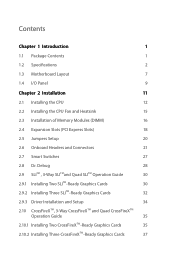
...Package Contents 1 1.2 Specifications 2 1.3 Motherboard Layout 7 1.4 I/O Panel 9 Chapter 2 Installation 11 2.1 Installing the CPU 12 2.2 Installing the CPU Fan and Heatsink 15 2.3 Installation of Memory Modules (DIMM) 16 2.4 Expansion Slots (PCI Express Slots) 18 2.5 Jumpers Setup 20 2.6 Onboard Headers and Connectors 21 2.7 Smart Switches 27 2.8 Dr. Debug 28 2.9 SLITM , 3-Way SLITMand Quad SLITM Operation Guide 30 2.9.1 Installing Two SLITM-Ready Graphics Cards 30 2.9.2 Installing Three SLITM-Ready Graphics Cards 32 2.9.3 Driver Installation and Setup 34 2.10...
...Package Contents 1 1.2 Specifications 2 1.3 Motherboard Layout 7 1.4 I/O Panel 9 Chapter 2 Installation 11 2.1 Installing the CPU 12 2.2 Installing the CPU Fan and Heatsink 15 2.3 Installation of Memory Modules (DIMM) 16 2.4 Expansion Slots (PCI Express Slots) 18 2.5 Jumpers Setup 20 2.6 Onboard Headers and Connectors 21 2.7 Smart Switches 27 2.8 Dr. Debug 28 2.9 SLITM , 3-Way SLITMand Quad SLITM Operation Guide 30 2.9.1 Installing Two SLITM-Ready Graphics Cards 30 2.9.2 Installing Three SLITM-Ready Graphics Cards 32 2.9.3 Driver Installation and Setup 34 2.10...
User Manual
Page 9
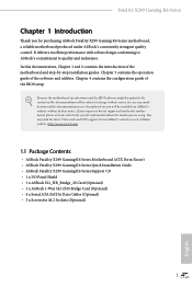
... Factor) • ASRock Fatal1ty X299 Gaming K6 Series Quick Installation Guide • ASRock Fatal1ty X299 Gaming K6 Series Support CD • 1 x I/O Panel Shield • 1 x ASRock SLI_HB_Bridge_2S Card (Optional) • 1 x ASRock 3-Way SLI-2S1S Bridge Card (Optional) • 4 x Serial ATA (SATA) Data Cables (Optional) • 3 x Screws for purchasing ASRock Fatal1ty X299 Gaming K6 Series motherboard, a reliable motherboard produced under ASRock's consistently stringent quality control. Because the motherboard specifications and the BIOS software might be updated, the content of...
... Factor) • ASRock Fatal1ty X299 Gaming K6 Series Quick Installation Guide • ASRock Fatal1ty X299 Gaming K6 Series Support CD • 1 x I/O Panel Shield • 1 x ASRock SLI_HB_Bridge_2S Card (Optional) • 1 x ASRock 3-Way SLI-2S1S Bridge Card (Optional) • 4 x Serial ATA (SATA) Data Cables (Optional) • 3 x Screws for purchasing ASRock Fatal1ty X299 Gaming K6 Series motherboard, a reliable motherboard produced under ASRock's consistently stringent quality control. Because the motherboard specifications and the BIOS software might be updated, the content of...
User Manual
Page 11
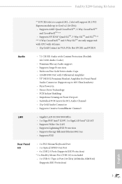
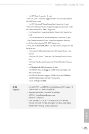
Fatal1ty X299 Gaming K6 Series ** If PCIE4 slot is occupied, M2_2 slot will support M.2 PCI Express module up to Gen3 x2 (16 Gb/s). • Supports AMD Quad CrossFireXTM, 3-Way CrossFireXTM and CrossFireXTM *** • Supports NVIDIA® Quad SLITM, 3-Way SLITM and SLITM*** *** 3-Way CrossFireXTM and 3-Way SLITM are only supported with CPU with 44 lanes. • 15μ Gold Contact in VGA PCIe Slot (PCIE1 and PCIE3) Audio • 7.1 CH...
Fatal1ty X299 Gaming K6 Series ** If PCIE4 slot is occupied, M2_2 slot will support M.2 PCI Express module up to Gen3 x2 (16 Gb/s). • Supports AMD Quad CrossFireXTM, 3-Way CrossFireXTM and CrossFireXTM *** • Supports NVIDIA® Quad SLITM, 3-Way SLITM and SLITM*** *** 3-Way CrossFireXTM and 3-Way SLITM are only supported with CPU with 44 lanes. • 15μ Gold Contact in VGA PCIe Slot (PCIE1 and PCIE3) Audio • 7.1 CH...
User Manual
Page 13
...support (1 x Main BIOS and 1 x Backup BIOS) • Supports Secure Backup UEFI Technology • ACPI 6.1 Compliant wake up events • SMBIOS 3.0 Support • CPU, DRAM, VPPM, VTTM, PCH 1.0V, VCCMPHY, VCCIO, VCCST, VCCSA, VCCSFR, VCCPLL, CLK VDD, PEGRCOMP Voltage Multi-adjustment English 5 nector) • 1 x 8 pin 12V Power Connector (Hi-Density Power Connec- tor) • 1 x Front Panel Audio Connector (15μ Gold Audio Connec- Fatal1ty X299 Gaming K6 Series BIOS Feature • 1 x CPU Fan Connector (4-pin) * The CPU Fan Connector supports the CPU fan of maximum 1A (12W) fan...
...support (1 x Main BIOS and 1 x Backup BIOS) • Supports Secure Backup UEFI Technology • ACPI 6.1 Compliant wake up events • SMBIOS 3.0 Support • CPU, DRAM, VPPM, VTTM, PCH 1.0V, VCCMPHY, VCCIO, VCCST, VCCSA, VCCSFR, VCCPLL, CLK VDD, PEGRCOMP Voltage Multi-adjustment English 5 nector) • 1 x 8 pin 12V Power Connector (Hi-Density Power Connec- tor) • 1 x Front Panel Audio Connector (15μ Gold Audio Connec- Fatal1ty X299 Gaming K6 Series BIOS Feature • 1 x CPU Fan Connector (4-pin) * The CPU Fan Connector supports the CPU fan of maximum 1A (12W) fan...

User Manual
Page 16
...pin DDR4 DIMM Slots (DDR4_C1, DDR4_D1) 7 CPU Fan Connector (CPU_FAN1) 8 RGB LED Header (RGB_LED2) 9 ATX Power Connector (ATXPWR1) 10 Virtual RAID On CPU Header (VROC1) 11 USB 3.0 Header (USB3_5_6) 12 USB 3.0 Header (USB3_7_8) 13 SATA3 Connectors (SATA3_0_1) 14 SATA3 Connectors (SATA3_2_3) 15 SATA3 Connectors (SATA3_4_5) 16 SATA3 Connectors (SATA3_6_7) 17 Power LED and Speaker Header (SPK_PLED1) 18 Chassis Fan Connector (CHA_FAN1) 19 System Panel Header (PANEL1) 20 Chassis Fan / Waterpump Fan Connector (CHA_FAN3/W_PUMP2) 21 USB 2.0 Header (USB_9_10) 22 USB 2.0 Header (USB_7_8) 23 USB 2.0 Header...
...pin DDR4 DIMM Slots (DDR4_C1, DDR4_D1) 7 CPU Fan Connector (CPU_FAN1) 8 RGB LED Header (RGB_LED2) 9 ATX Power Connector (ATXPWR1) 10 Virtual RAID On CPU Header (VROC1) 11 USB 3.0 Header (USB3_5_6) 12 USB 3.0 Header (USB3_7_8) 13 SATA3 Connectors (SATA3_0_1) 14 SATA3 Connectors (SATA3_2_3) 15 SATA3 Connectors (SATA3_4_5) 16 SATA3 Connectors (SATA3_6_7) 17 Power LED and Speaker Header (SPK_PLED1) 18 Chassis Fan Connector (CHA_FAN1) 19 System Panel Header (PANEL1) 20 Chassis Fan / Waterpump Fan Connector (CHA_FAN3/W_PUMP2) 21 USB 2.0 Header (USB_9_10) 22 USB 2.0 Header (USB_7_8) 23 USB 2.0 Header...
User Manual
Page 17
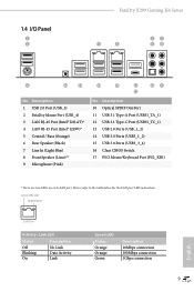
... SPDIF Out Port 11 USB 3.1 Type-A Port (USB31_TA_1) 12 USB 3.1 Type-C Port (USB31_TC_1) 13 USB 2.0 Ports (USB_1_2) 14 USB 3.0 Ports (USB3_1_2) 15 USB 3.0 Ports (USB3_3_4) 16 Clear CMOS Switch 17 PS/2 Mouse/Keyboard Port (PS2_KB1) * There are two LEDs on each LAN port. ACT/LINK LED SPEED LED LAN Port Activity / Link LED Status Description Off Blinking On No Link Data Activity Link Speed LED Status Orange Orange Green Description 10Mbps connection 100Mbps connection 1Gbps connection 9 English Description 1 USB 2.0 Port (USB_3) 2 Fatal1ty Mouse Port (USB_4) 3 LAN RJ-45 Port...
... SPDIF Out Port 11 USB 3.1 Type-A Port (USB31_TA_1) 12 USB 3.1 Type-C Port (USB31_TC_1) 13 USB 2.0 Ports (USB_1_2) 14 USB 3.0 Ports (USB3_1_2) 15 USB 3.0 Ports (USB3_3_4) 16 Clear CMOS Switch 17 PS/2 Mouse/Keyboard Port (PS2_KB1) * There are two LEDs on each LAN port. ACT/LINK LED SPEED LED LAN Port Activity / Link LED Status Description Off Blinking On No Link Data Activity Link Speed LED Status Orange Orange Green Description 10Mbps connection 100Mbps connection 1Gbps connection 9 English Description 1 USB 2.0 Port (USB_3) 2 Fatal1ty Mouse Port (USB_4) 3 LAN RJ-45 Port...
User Manual
Page 29
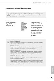
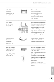
Fatal1ty X299 Gaming K6 Series 2.6 Onboard Headers and Connectors Onboard headers and connectors are matched correctly. Do NOT place jumper caps over the headers and connectors will cause permanent damage to the power status indicator on the chassis front panel. Placing jumper caps over these headers and connectors. You may differ by chassis. PLED (System Power LED): Connect to the motherboard. HDLED (Hard Drive Activity LED): Connect to the reset switch on when the hard drive is on the chassis front panel. The LED is in S1...
Fatal1ty X299 Gaming K6 Series 2.6 Onboard Headers and Connectors Onboard headers and connectors are matched correctly. Do NOT place jumper caps over the headers and connectors will cause permanent damage to the power status indicator on the chassis front panel. Placing jumper caps over these headers and connectors. You may differ by chassis. PLED (System Power LED): Connect to the motherboard. HDLED (Hard Drive Activity LED): Connect to the reset switch on when the hard drive is on the chassis front panel. The LED is in S1...
User Manual
Page 31
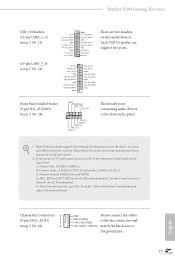
... for the HD audio panel only. If you use an AC'97 audio panel, please install it to connect them for connecting audio devices to the front audio panel. 1. You don't need to the front panel audio header by the steps below: A. Connect Ground (GND) to function correctly. GND IntA_PB_SSRX+ IntA_PB_SSRX- E. B. D. C. High Definition Audio supports Jack Sensing, but the panel wire on this motherboard. Connect Mic_IN (MIC) to OUT2_L. English Chassis Fan Connectors 1 (4-pin CHA_FAN1) 2 3 (see p.7, No...
... for the HD audio panel only. If you use an AC'97 audio panel, please install it to connect them for connecting audio devices to the front audio panel. 1. You don't need to the front panel audio header by the steps below: A. Connect Ground (GND) to function correctly. GND IntA_PB_SSRX+ IntA_PB_SSRX- E. B. D. C. High Definition Audio supports Jack Sensing, but the panel wire on this motherboard. Connect Mic_IN (MIC) to OUT2_L. English Chassis Fan Connectors 1 (4-pin CHA_FAN1) 2 3 (see p.7, No...
User Manual
Page 33
... headers are used to connect RGB LED extension cable which can securely store keys, digital certificates, passwords, and data. English 25 To use a 4-pin ATX power supply, please plug it along Pin 1 and Pin 5. Caution: Never install the RGB LED cable in card (AIC) to choose from various LED lighting effects. Please connect a Thunderbolt™ add-in the wrong orientation; Fatal1ty X299 Gaming K6 Series ATX 12V Power Connector (8-pin ATX12V1) (see p.7, No. 3) 8 5 4 1 TPM Header (17-pin TPMS1) (see p.7, No. 24) 1 Thunderbolt AIC Connector (5-pin...
... headers are used to connect RGB LED extension cable which can securely store keys, digital certificates, passwords, and data. English 25 To use a 4-pin ATX power supply, please plug it along Pin 1 and Pin 5. Caution: Never install the RGB LED cable in card (AIC) to choose from various LED lighting effects. Please connect a Thunderbolt™ add-in the wrong orientation; Fatal1ty X299 Gaming K6 Series ATX 12V Power Connector (8-pin ATX12V1) (see p.7, No. 3) 8 5 4 1 TPM Header (17-pin TPMS1) (see p.7, No. 24) 1 Thunderbolt AIC Connector (5-pin...
User Manual
Page 36
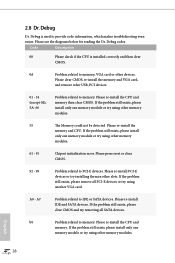
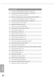
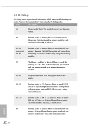
...-install the CPU and memory then clear CMOS. If the problem still exists, please remove all SATA devices. Please re-install IDE and SATA devices. If the problem still exists, please install only one memory module or try installing them in other USB, PCI devices. 01 - 54 (except 0d), 5A- 60 Problem related to memory, VGA card or other memory modules. 61 - 91 Chipset initialization error. Please clear CMOS, re-install the memory and VGA card, and remove other slots. Please re-install PCI-E devices or try using other memory...
...-install the CPU and memory then clear CMOS. If the problem still exists, please remove all SATA devices. Please re-install IDE and SATA devices. If the problem still exists, please install only one memory module or try installing them in other USB, PCI devices. 01 - 54 (except 0d), 5A- 60 Problem related to memory, VGA card or other memory modules. 61 - 91 Chipset initialization error. Please clear CMOS, re-install the memory and VGA card, and remove other slots. Please re-install PCI-E devices or try using other memory...
User Manual
Page 43
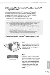
... refer to three identical PCI Express x16 graphics cards. Download the drivers from the AMD's website: www.amd.com 3. It is only supported with CPU with this motherboard. Different CrossFireXTM cards may require different methods to use identical CrossFireXTM-ready graphics cards that the cards are supported with Windows® 10 64-bit OS. * 3-Way CrossFireXTM is recommended to enable CrossFireXTM. English CrossFire Bridge Step 2 Connect two graphics cards by installing a CrossFire Bridge on...
... refer to three identical PCI Express x16 graphics cards. Download the drivers from the AMD's website: www.amd.com 3. It is only supported with CPU with this motherboard. Different CrossFireXTM cards may require different methods to use identical CrossFireXTM-ready graphics cards that the cards are supported with Windows® 10 64-bit OS. * 3-Way CrossFireXTM is recommended to enable CrossFireXTM. English CrossFire Bridge Step 2 Connect two graphics cards by installing a CrossFire Bridge on...
User Manual
Page 46
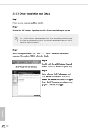
We recommend using this utility to uninstall any VGA drivers installed in the Windows® system tray. Please check AMD's website for AMD driver updates. Select the GPU number according to installation. Please check AMD's website for details. AMD Catalyst Control Center Step 4 Double-click the AMD Catalyst Control Center icon in your graphics card and click Apply. 2.10.3 Driver Installation and Setup Step 1 Power on your computer. English 38 Step 2 Remove the AMD drivers if...
We recommend using this utility to uninstall any VGA drivers installed in the Windows® system tray. Please check AMD's website for AMD driver updates. Select the GPU number according to installation. Please check AMD's website for details. AMD Catalyst Control Center Step 4 Double-click the AMD Catalyst Control Center icon in your graphics card and click Apply. 2.10.3 Driver Installation and Setup Step 1 Power on your computer. English 38 Step 2 Remove the AMD drivers if...
User Manual
Page 51
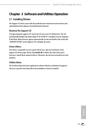
..., locate and double click on the support CD driver page. Utilities Menu The Utilities Menu shows the application software that enhance the motherboard's features. Drivers Menu The drivers compatible to install those required drivers. Therefore, the drivers you install can work properly. Click on a specific item then follow the order from top to bottom to your system will be auto-detected and listed on the file "ASRSETUP.EXE" in your CD-ROM drive. Fatal1ty X299 Gaming K6 Series Chapter 3 Software...
..., locate and double click on the support CD driver page. Utilities Menu The Utilities Menu shows the application software that enhance the motherboard's features. Drivers Menu The drivers compatible to install those required drivers. Therefore, the drivers you install can work properly. Click on a specific item then follow the order from top to bottom to your system will be auto-detected and listed on the file "ASRSETUP.EXE" in your CD-ROM drive. Fatal1ty X299 Gaming K6 Series Chapter 3 Software...
User Manual
Page 96
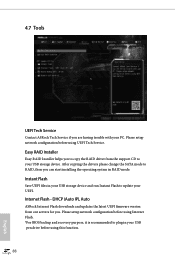
...using UEFI Tech Service. After copying the drivers please change the SATA mode to update your UEFI. Instant Flash Save UEFI files in your USB storage device. Please setup network configuration before using this function. 88 English Internet Flash - Please setup network configuration before using Internet Flash. *For BIOS backup and recovery purpose, it is recommended to your USB storage device and run Instant Flash to RAID, then you . DHCP (Auto IP), Auto ASRock Internet Flash downloads and updates the latest UEFI firmware version from the support CD to plug in RAID mode...
...using UEFI Tech Service. After copying the drivers please change the SATA mode to update your UEFI. Instant Flash Save UEFI files in your USB storage device. Please setup network configuration before using this function. 88 English Internet Flash - Please setup network configuration before using Internet Flash. *For BIOS backup and recovery purpose, it is recommended to your USB storage device and run Instant Flash to RAID, then you . DHCP (Auto IP), Auto ASRock Internet Flash downloads and updates the latest UEFI firmware version from the support CD to plug in RAID mode...
User Manual
Page 97
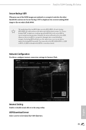
... working copy of your system. Internet Setting Enable or disable sound effects in the setup utility. UEFI Download Server Select a server to update the backup BIOS manually. This motherboard has two BIOS chips, an active BIOS (BIOS_A) and a backup BIOS (BIOS_B), which BIOS is corrupted or damaged, after several failed boot attempts, the backup BIOS will work on the active BIOS. However if the active BIOS is currently activated. Users may refer to the BIOS LEDs...
... working copy of your system. Internet Setting Enable or disable sound effects in the setup utility. UEFI Download Server Select a server to update the backup BIOS manually. This motherboard has two BIOS chips, an active BIOS (BIOS_A) and a backup BIOS (BIOS_B), which BIOS is corrupted or damaged, after several failed boot attempts, the backup BIOS will work on the active BIOS. However if the active BIOS is currently activated. Users may refer to the BIOS LEDs...
User Manual
Page 101
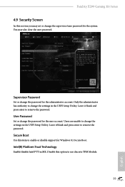
... to change the settings in ME. Intel(R) Platform Trust Technology Enable/disable Intel PTT in the UEFI Setup Utility. Disable this option to remove the password. You may set or change the supervisor/user password for Windows 8.1 Secure Boot. Only the administrator has authority to change the settings in the UEFI Setup Utility. Secure Boot Use this item to remove the password. Fatal1ty X299 Gaming K6 Series 4.9 Security Screen In this section you may also clear the user password. Leave it blank and press enter to enable or disable support...
... to change the settings in ME. Intel(R) Platform Trust Technology Enable/disable Intel PTT in the UEFI Setup Utility. Disable this option to remove the password. You may set or change the supervisor/user password for Windows 8.1 Secure Boot. Only the administrator has authority to change the settings in the UEFI Setup Utility. Secure Boot Use this item to remove the password. Fatal1ty X299 Gaming K6 Series 4.9 Security Screen In this section you may also clear the user password. Leave it blank and press enter to enable or disable support...
Quick Installation Guide
Page 6
...pin DDR4 DIMM Slots (DDR4_C1, DDR4_D1) 7 CPU Fan Connector (CPU_FAN1) 8 RGB LED Header (RGB_LED2) 9 ATX Power Connector (ATXPWR1) 10 Virtual RAID On CPU Header (VROC1) 11 USB 3.0 Header (USB3_5_6) 12 USB 3.0 Header (USB3_7_8) 13 SATA3 Connectors (SATA3_0_1) 14 SATA3 Connectors (SATA3_2_3) 15 SATA3 Connectors (SATA3_4_5) 16 SATA3 Connectors (SATA3_6_7) 17 Power LED and Speaker Header (SPK_PLED1) 18 Chassis Fan Connector (CHA_FAN1) 19 System Panel Header (PANEL1) 20 Chassis Fan / Waterpump Fan Connector (CHA_FAN3/W_PUMP2) 21 USB 2.0 Header (USB_9_10) 22 USB 2.0 Header (USB_7_8) 23 USB 2.0 Header...
...pin DDR4 DIMM Slots (DDR4_C1, DDR4_D1) 7 CPU Fan Connector (CPU_FAN1) 8 RGB LED Header (RGB_LED2) 9 ATX Power Connector (ATXPWR1) 10 Virtual RAID On CPU Header (VROC1) 11 USB 3.0 Header (USB3_5_6) 12 USB 3.0 Header (USB3_7_8) 13 SATA3 Connectors (SATA3_0_1) 14 SATA3 Connectors (SATA3_2_3) 15 SATA3 Connectors (SATA3_4_5) 16 SATA3 Connectors (SATA3_6_7) 17 Power LED and Speaker Header (SPK_PLED1) 18 Chassis Fan Connector (CHA_FAN1) 19 System Panel Header (PANEL1) 20 Chassis Fan / Waterpump Fan Connector (CHA_FAN3/W_PUMP2) 21 USB 2.0 Header (USB_9_10) 22 USB 2.0 Header (USB_7_8) 23 USB 2.0 Header...
Quick Installation Guide
Page 9
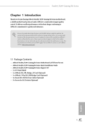
... X299 Gaming K6 Series Quick Installation Guide • ASRock Fatal1ty X299 Gaming K6 Series Support CD • 1 x I/O Panel Shield • 1 x ASRock SLI_HB_Bridge_2S Card (Optional) • 1 x ASRock 3-Way SLI-2S1S Bridge Card (Optional) • 4 x Serial ATA (SATA) Data Cables (Optional) • 3 x Screws for purchasing ASRock Fatal1ty X299 Gaming K6 Series motherboard, a reliable motherboard produced under ASRock's consistently stringent quality control. Fatal1ty X299 Gaming K6 Series Chapter 1 Introduction Thank you are using. Because the motherboard specifications and the BIOS...
... X299 Gaming K6 Series Quick Installation Guide • ASRock Fatal1ty X299 Gaming K6 Series Support CD • 1 x I/O Panel Shield • 1 x ASRock SLI_HB_Bridge_2S Card (Optional) • 1 x ASRock 3-Way SLI-2S1S Bridge Card (Optional) • 4 x Serial ATA (SATA) Data Cables (Optional) • 3 x Screws for purchasing ASRock Fatal1ty X299 Gaming K6 Series motherboard, a reliable motherboard produced under ASRock's consistently stringent quality control. Fatal1ty X299 Gaming K6 Series Chapter 1 Introduction Thank you are using. Because the motherboard specifications and the BIOS...
Quick Installation Guide
Page 32
... exists, please clear CMOS and try installing them in other USB, PCI devices. 01 - 54 (except 0d), 5A- 60 Problem related to IDE or SATA devices. Please re-install PCI-E devices or try removing all PCI-E devices or try using another VGA card. A0 - Please clear CMOS, re-install the memory and VGA card, and remove other slots. A7 Problem related to memory. Please re-install the CPU and memory. Code Description 00 Please check if the CPU is used to memory, VGA card or other memory modules. If...
... exists, please clear CMOS and try installing them in other USB, PCI devices. 01 - 54 (except 0d), 5A- 60 Problem related to IDE or SATA devices. Please re-install PCI-E devices or try removing all PCI-E devices or try using another VGA card. A0 - Please clear CMOS, re-install the memory and VGA card, and remove other slots. A7 Problem related to memory. Please re-install the CPU and memory. Code Description 00 Please check if the CPU is used to memory, VGA card or other memory modules. If...
RAID Installation Guide
Page 7
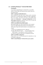
... Items After installing the hard disk drives, please set the necessary RAID items in UEFI setup. STEP 2: Use ASRock Easy RAID Installer Easy RAID Installer can copy the RAID driver from a support CD to your USB storage device with RAID functions, please follow the procedures below. Plug in your system. 7 Enter UEFI SETUP UTILITY Tool and highlight "Easy RAID Installer". Boot your system, and press key to [RAID]. Go to Advanced Storage Configuration and set RAID configuration. STEP 4: Install Windows® 10 64-bit OS on your USB flash drive into a USB port...
... Items After installing the hard disk drives, please set the necessary RAID items in UEFI setup. STEP 2: Use ASRock Easy RAID Installer Easy RAID Installer can copy the RAID driver from a support CD to your USB storage device with RAID functions, please follow the procedures below. Plug in your system. 7 Enter UEFI SETUP UTILITY Tool and highlight "Easy RAID Installer". Boot your system, and press key to [RAID]. Go to Advanced Storage Configuration and set RAID configuration. STEP 4: Install Windows® 10 64-bit OS on your USB flash drive into a USB port...


