User Manual
Page 9
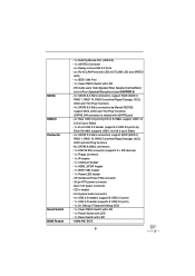
...3.0 Ports - 2 x RJ-45 LAN Ports with LED (ACT/LINK LED and SPEED LED) - 1 x IEEE 1394 Port - 1 x Clear CMOS Switch with LED - 64Mb AMI BIOS 9 Front panel audio connector - 4 x USB 2.0 headers (support 8 USB 2.0 ports) - 1 x USB 3.0 header (supports 2 USB 3.0 ports) - 1 x Dr. Debug .../Rear Speaker/Central/Bass/ Line in header - SATA3 USB3.0 Connector Smart Switch BIOS Feature - 1 x Fatal1ty Mouse Port (USB 2.0) - 1 x eSATA3 Connector - 4 x Ready-to 5Gb/s - 4 x SATA2 3.0 Gb/s connectors, support RAID (RAID 0, RAID 1, RAID 10, RAID 5 and Intel Rapid Storage), NCQ, AHCI and Hot Plug functions ...
...3.0 Ports - 2 x RJ-45 LAN Ports with LED (ACT/LINK LED and SPEED LED) - 1 x IEEE 1394 Port - 1 x Clear CMOS Switch with LED - 64Mb AMI BIOS 9 Front panel audio connector - 4 x USB 2.0 headers (support 8 USB 2.0 ports) - 1 x USB 3.0 header (supports 2 USB 3.0 ports) - 1 x Dr. Debug .../Rear Speaker/Central/Bass/ Line in header - SATA3 USB3.0 Connector Smart Switch BIOS Feature - 1 x Fatal1ty Mouse Port (USB 2.0) - 1 x eSATA3 Connector - 4 x Ready-to 5Gb/s - 4 x SATA2 3.0 Gb/s connectors, support RAID (RAID 0, RAID 1, RAID 10, RAID 5 and Intel Rapid Storage), NCQ, AHCI and Hot Plug functions ...
User Manual
Page 10
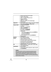
...Combo Cooler Option (C.C.O.) (see CAUTION 6) - CPU/Chassis Quiet Fan (Allow Chassis Fan Speed Auto-Adjust by overclocking. 10 FCC, CE, WHQL - It should be done at your system. CPU Temperature Sensing - CPU/Chassis/Power Fan Tachometer - AMI UEFI Legal... BIOS with overclocking, including adjusting the setting in the BIOS, applying Untied Overclocking Technology, or using the third-party overclocking tools. APP Charger (see CAUTION 10) - SmartView (see CAUTION 9) - Supports jumperfree - CPU ...
...Combo Cooler Option (C.C.O.) (see CAUTION 6) - CPU/Chassis Quiet Fan (Allow Chassis Fan Speed Auto-Adjust by overclocking. 10 FCC, CE, WHQL - It should be done at your system. CPU Temperature Sensing - CPU/Chassis/Power Fan Tachometer - AMI UEFI Legal... BIOS with overclocking, including adjusting the setting in the BIOS, applying Untied Overclocking Technology, or using the third-party overclocking tools. APP Charger (see CAUTION 10) - SmartView (see CAUTION 9) - Supports jumperfree - CPU ...
User Manual
Page 16
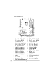
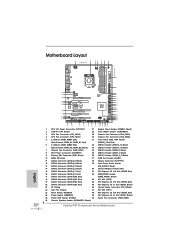
... Bottom: MIC IN PWR_FAN1 50 49 PCIE1 RoHS 48 AUDIO CODEC PCIE2 64Mb BIOS SATA2_4_5 SATA2_2_3 47 46 45 44 43 42 41 40 PCI1 CD1 Super I/O Dual GLAN PCIE3 CMOS Battery Fatal1ty PCIE4 P67 Professional PCI2 Front USB 3.0 1 HDMI_SPDIF1 HD_AUDIO1 1 IR1 SATA3 1 FLOPPY1 1 PCIE5...) 8 ATX Power Connector (ATXPWR1) 35 USB 2.0 Header (USB6_7, Black) 9 Primary IDE Connector (IDE1, Black) 36 USB 3.0 Header (USB3_2_3, Black) 10 64Mb SPI Flash 37 COM Port Header (COM1) 11 SATA2 Connector (SATA2_5, Black) 38 Floppy Connector (FLOPPY1) 12 SATA2 Connector (SATA2_4, Black) 39 Front...
... Bottom: MIC IN PWR_FAN1 50 49 PCIE1 RoHS 48 AUDIO CODEC PCIE2 64Mb BIOS SATA2_4_5 SATA2_2_3 47 46 45 44 43 42 41 40 PCI1 CD1 Super I/O Dual GLAN PCIE3 CMOS Battery Fatal1ty PCIE4 P67 Professional PCI2 Front USB 3.0 1 HDMI_SPDIF1 HD_AUDIO1 1 IR1 SATA3 1 FLOPPY1 1 PCIE5...) 8 ATX Power Connector (ATXPWR1) 35 USB 2.0 Header (USB6_7, Black) 9 Primary IDE Connector (IDE1, Black) 36 USB 3.0 Header (USB3_2_3, Black) 10 64Mb SPI Flash 37 COM Port Header (COM1) 11 SATA2 Connector (SATA2_5, Black) 38 Floppy Connector (FLOPPY1) 12 SATA2 Connector (SATA2_4, Black) 39 Front...
User Manual
Page 36
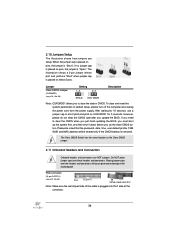
...-pin FLOPPY1) (see p.16, No. 28) Setting Default Clear CMOS Description Note: CLRCMOS1 allows you update the BIOS. If you need to clear the CMOS when you just finish updating the BIOS, you must boot up the system first, and then shut it down before you do not clear... is removed. To clear and reset the system parameters to short pin2 and pin3 on pins, the jumper is "Open". After waiting for 5 seconds. 2.10 Jumpers Setup The illustration shows how jumpers are NOT jumpers. If no jumper cap is placed on these headers and connectors. The illustration shows a 3-pin...
...-pin FLOPPY1) (see p.16, No. 28) Setting Default Clear CMOS Description Note: CLRCMOS1 allows you update the BIOS. If you need to clear the CMOS when you just finish updating the BIOS, you must boot up the system first, and then shut it down before you do not clear... is removed. To clear and reset the system parameters to short pin2 and pin3 on pins, the jumper is "Open". After waiting for 5 seconds. 2.10 Jumpers Setup The illustration shows how jumpers are NOT jumpers. If no jumper cap is placed on these headers and connectors. The illustration shows a 3-pin...
Quick Installation Guide
Page 4
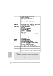
... Center: Bottom: PWR_FAN1 1 2 3 4 5 6 7 8 9 10 11 12 13 14 15 16 17 18 19 20 21 22 23 24 25 26 4 50 49 PCIE1 RoHS 48 AUDIO CODEC PCIE2 64Mb BIOS SATA2_4_5 SATA2_2_3 SATA3_0_1 SATA3_M3_M4 SATA3_M1_M2 47 PCI1 46 45 CD1 Dual GLAN Super PCIE3 CMOS Battery I/O Fatal1ty 44 PCIE4 P67 Professional Intel P67 43 42 41...
... Center: Bottom: PWR_FAN1 1 2 3 4 5 6 7 8 9 10 11 12 13 14 15 16 17 18 19 20 21 22 23 24 25 26 4 50 49 PCIE1 RoHS 48 AUDIO CODEC PCIE2 64Mb BIOS SATA2_4_5 SATA2_2_3 SATA3_0_1 SATA3_M3_M4 SATA3_M1_M2 47 PCI1 46 45 CD1 Dual GLAN Super PCIE3 CMOS Battery I/O Fatal1ty 44 PCIE4 P67 Professional Intel P67 43 42 41...
Quick Installation Guide
Page 9
...with LED (ACT/LINK LED and SPEED LED) - 1 x IEEE 1394 Port - 1 x Clear CMOS Switch with LED - 64Mb AMI BIOS 9 Fatal1ty P67 Professional Series Motherboard English CPU/Chassis/Power FAN connector - 24 pin ATX power connector - 8 pin 12V power connector - Front panel audio connector -... LED - 1 x Reset Switch with LED - SATA3 USB3.0 Connector Smart Switch BIOS Feature - 1 x Fatal1ty Mouse Port (USB 2.0) - 1 x eSATA3 Connector - 4 x Ready-to 5Gb/s - 4 x SATA2 3.0 Gb/s connectors, support RAID (RAID 0, RAID 1, RAID 10, RAID 5 and Intel Rapid Storage), NCQ, AHCI and Hot Plug functions - ...
...with LED (ACT/LINK LED and SPEED LED) - 1 x IEEE 1394 Port - 1 x Clear CMOS Switch with LED - 64Mb AMI BIOS 9 Fatal1ty P67 Professional Series Motherboard English CPU/Chassis/Power FAN connector - 24 pin ATX power connector - 8 pin 12V power connector - Front panel audio connector -... LED - 1 x Reset Switch with LED - SATA3 USB3.0 Connector Smart Switch BIOS Feature - 1 x Fatal1ty Mouse Port (USB 2.0) - 1 x eSATA3 Connector - 4 x Ready-to 5Gb/s - 4 x SATA2 3.0 Gb/s connectors, support RAID (RAID 0, RAID 1, RAID 10, RAID 5 and Intel Rapid Storage), NCQ, AHCI and Hot Plug functions - ...
Quick Installation Guide
Page 10
...Trial Version), Software Suite (CyberLink DVD Suite - CPU Temperature Sensing - English 10 Fatal1ty P67 Professional Series Motherboard AMI UEFI Legal BIOS with overclocking, including adjusting the setting in the BIOS, applying Untied Overclocking Technology, or using the third-party overclocking tools. Instant ...Boot - Instant Flash (see CAUTION 10) - SmartView (see CAUTION 7) - Boot Failure Guard (B.F.G.) - CPU/Chassis...
...Trial Version), Software Suite (CyberLink DVD Suite - CPU Temperature Sensing - English 10 Fatal1ty P67 Professional Series Motherboard AMI UEFI Legal BIOS with overclocking, including adjusting the setting in the BIOS, applying Untied Overclocking Technology, or using the third-party overclocking tools. Instant ...Boot - Instant Flash (see CAUTION 10) - SmartView (see CAUTION 7) - Boot Failure Guard (B.F.G.) - CPU/Chassis...
Quick Installation Guide
Page 216
... UEFI 적합형 BIOS Fatal1ty P67 Professional Series Motherboard 한 국 어 SATA3 USB 3.0 BIOS 216 - 2 개 LED(ACT/LINK LED 및 SPEED LED RJ-45 LAN 포트 - 1 개 IEEE 1394 포트 - 1 개 LED 가 달린 CMOS 5 참조 ) - SATA3 6.0Gb/s 커넥터 2 RAID (RAID 0, RAID 1, RAID 10, RAID 5 및 Intel...
... UEFI 적합형 BIOS Fatal1ty P67 Professional Series Motherboard 한 국 어 SATA3 USB 3.0 BIOS 216 - 2 개 LED(ACT/LINK LED 및 SPEED LED RJ-45 LAN 포트 - 1 개 IEEE 1394 포트 - 1 개 LED 가 달린 CMOS 5 참조 ) - SATA3 6.0Gb/s 커넥터 2 RAID (RAID 0, RAID 1, RAID 10, RAID 5 및 Intel...
Quick Installation Guide
Page 245
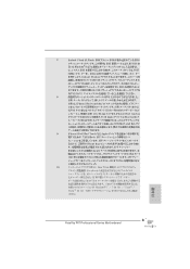
7. iPhone/iPod/iPad Touch など Apple ASRock APP APP iPhone 40 APP Apple 製品は PC S1 S3 (S4 S5 APP チャー 10. SmartView Facebook IE SmartView SmartView OS Windows® 7 / 7 64 bit / VistaTM / VistaTM 64 bit IE8 日本語 245 Fatal1ty P67 Professional Series Motherboard Wii AIWI PC AIWI は...
7. iPhone/iPod/iPad Touch など Apple ASRock APP APP iPhone 40 APP Apple 製品は PC S1 S3 (S4 S5 APP チャー 10. SmartView Facebook IE SmartView SmartView OS Windows® 7 / 7 64 bit / VistaTM / VistaTM 64 bit IE8 日本語 245 Fatal1ty P67 Professional Series Motherboard Wii AIWI PC AIWI は...
Quick Installation Guide
Page 267
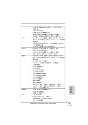
...; 5Gb/s - 1 x Etron EJ168A 的前置 USB 3.0 2 個 USB 3.0 USB 1.0/2.0/3.0 到 5Gb/s - 4 x SATA2 3.0Gb/s RAID (RAID 0, RAID 1, RAID 10, RAID 5 和 Intel Rapid Storage), NCQ, AHCI 6 x SATA3 6.0Gb/s 1 x ATA133 IDE 2 個 IDE 1 x 1 x 1 x 1 x HDMI_SPDIF 接頭 -... LED) - 1 個帶 LED 的 CMOS 1 個帶 LED 1 個帶 LED 64Mb AMI BIOS - AMI UEFI Legal BIOS,支持 GUI Plug and Play,PnP) - ACPI 1.1 267 Fatal1ty P67 Professional Series Motherboard 簡體中文
...; 5Gb/s - 1 x Etron EJ168A 的前置 USB 3.0 2 個 USB 3.0 USB 1.0/2.0/3.0 到 5Gb/s - 4 x SATA2 3.0Gb/s RAID (RAID 0, RAID 1, RAID 10, RAID 5 和 Intel Rapid Storage), NCQ, AHCI 6 x SATA3 6.0Gb/s 1 x ATA133 IDE 2 個 IDE 1 x 1 x 1 x 1 x HDMI_SPDIF 接頭 -... LED) - 1 個帶 LED 的 CMOS 1 個帶 LED 1 個帶 LED 64Mb AMI BIOS - AMI UEFI Legal BIOS,支持 GUI Plug and Play,PnP) - ACPI 1.1 267 Fatal1ty P67 Professional Series Motherboard 簡體中文
Quick Installation Guide
Page 268
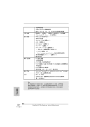
...® Windows® 7/7 64 位元 /VistaTM/VistaTM 64 位元 / XP/XP 64 FCC, CE, WHQL - 支持 ErP/EuP ErP/EuP 14) BIOS 簡體中文 268 Fatal1ty P67 Professional Series Motherboard APP Charger 9) - SmartView 10) -
...® Windows® 7/7 64 位元 /VistaTM/VistaTM 64 位元 / XP/XP 64 FCC, CE, WHQL - 支持 ErP/EuP ErP/EuP 14) BIOS 簡體中文 268 Fatal1ty P67 Professional Series Motherboard APP Charger 9) - SmartView 10) -
Quick Installation Guide
Page 292
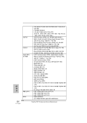
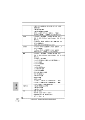
... 10, RAID 5 和 Intel Rapid Storage), NCQ, AHCI 6 x SATA3 6.0Gb/s 接頭 - 1 x ATA133 IDE 2 個 IDE 1 x 1 x 1 x 1 x HDMI_SPDIF 接頭 - 1 x IEEE 1394 接頭 - 1 x CPU 24 針 ATX 8 針 12V 4 x USB 2.0 8 USB 2.0 接口 ) - 1 x USB 3.0 2 USB 3.0 接口 ) - 1 x Dr. Debug (7 LED) - 1 個 LED CMOS 1 個 LED 1 個 LED 64Mb AMI BIOS - ACPI 1.1 Fatal1ty P67 Professional Series...
... 10, RAID 5 和 Intel Rapid Storage), NCQ, AHCI 6 x SATA3 6.0Gb/s 接頭 - 1 x ATA133 IDE 2 個 IDE 1 x 1 x 1 x 1 x HDMI_SPDIF 接頭 - 1 x IEEE 1394 接頭 - 1 x CPU 24 針 ATX 8 針 12V 4 x USB 2.0 8 USB 2.0 接口 ) - 1 x USB 3.0 2 USB 3.0 接口 ) - 1 x Dr. Debug (7 LED) - 1 個 LED CMOS 1 個 LED 1 個 LED 64Mb AMI BIOS - ACPI 1.1 Fatal1ty P67 Professional Series...
Quick Installation Guide
Page 293
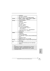
... - AIWI 8) - FCC, CE, WHQL - 支援 ErP/EuP ErP/EuP 14) BIOS 繁體中文 293 Fatal1ty P67 Professional Series Motherboard Hybrid Booster - 支援 CPU 11) - OEM F-Stream 6 Instant Flash 7) - APP Charger 9) - SmartView 10) - Boot Failure Guard (B.F.G C.C.O 13 LED CPU CPU CPU CPU 或 MB CPU 12V...
... - AIWI 8) - FCC, CE, WHQL - 支援 ErP/EuP ErP/EuP 14) BIOS 繁體中文 293 Fatal1ty P67 Professional Series Motherboard Hybrid Booster - 支援 CPU 11) - OEM F-Stream 6 Instant Flash 7) - APP Charger 9) - SmartView 10) - Boot Failure Guard (B.F.G C.C.O 13 LED CPU CPU CPU CPU 或 MB CPU 12V...


