
Intel Rapid Storage Guide
Page 12
Enable RAID in System BIOS Use the instructions included with your motherboard to select the physical disks. 6. When the Intel Rapid Storage Technology option ROM status screen appears during operating system setup. Unless you have selected RAID 1, ...
Enable RAID in System BIOS Use the instructions included with your motherboard to select the physical disks. 6. When the Intel Rapid Storage Technology option ROM status screen appears during operating system setup. Unless you have selected RAID 1, ...
User Manual
Page 4
...in this manual are used under license. © 2010 Fatal1ty, Inc. This device complies with Part 15 of merchantability or fitness for backup purpose. All rights reserved. Fatal1ty website: www.fatal1ty.com 4 In no responsibility for loss of profi...harmful interference, and (2) this motherboard contains Perchlorate, a toxic substance controlled in advance. "Perchlorate Material-special handling may apply, see www.dtsc.ca.gov/hazardouswaste/perchlorate" The Fatal1ty name, Fatal1ty logos and the Fatal1ty likeness are registered trademarks of Fatal1ty, Inc., and are the ...
...in this manual are used under license. © 2010 Fatal1ty, Inc. This device complies with Part 15 of merchantability or fitness for backup purpose. All rights reserved. Fatal1ty website: www.fatal1ty.com 4 In no responsibility for loss of profi...harmful interference, and (2) this motherboard contains Perchlorate, a toxic substance controlled in advance. "Perchlorate Material-special handling may apply, see www.dtsc.ca.gov/hazardouswaste/perchlorate" The Fatal1ty name, Fatal1ty logos and the Fatal1ty likeness are registered trademarks of Fatal1ty, Inc., and are the ...
User Manual
Page 5
Contents 1 Introduction 7 1.1 Package Contents 7 1.2 Specifications 8 1.3 Motherboard Layout 16 1.4 I/O Panel 17 2 Installation 19 2.1 Screw Holes 19 2.2 Pre-installation Precautions 19 2.3 CPU Installation 20 2.4 Installation of Heatsink and CPU fan 22 2.5 Installation of ...
Contents 1 Introduction 7 1.1 Package Contents 7 1.2 Specifications 8 1.3 Motherboard Layout 16 1.4 I/O Panel 17 2 Installation 19 2.1 Screw Holes 19 2.2 Pre-installation Precautions 19 2.3 CPU Installation 20 2.4 Installation of Heatsink and CPU fan 22 2.5 Installation of ...
User Manual
Page 7
...the BIOS software might be updated, the content of this manual, chapter 1 and 2 contain introduction of the motherboard and stepby-step guide to the "User Manual" in our support CD for details. 7 To get better ...Contents Fatal1ty P67 Professional Series Motherboard (ATX Form Factor: 12.0-in x 9.6-in, 30.5 cm x 24.4 cm) Fatal1ty P67 Professional Series Quick Installation Guide Fatal1ty P67 Professional Series Support CD 1 x 80-conductor Ultra ATA 66/100/133 IDE Ribbon Cable 1 x Ribbon Cable for purchasing Fatal1ty P67 Professional Series motherboard, a reliable motherboard produced...
...the BIOS software might be updated, the content of this manual, chapter 1 and 2 contain introduction of the motherboard and stepby-step guide to the "User Manual" in our support CD for details. 7 To get better ...Contents Fatal1ty P67 Professional Series Motherboard (ATX Form Factor: 12.0-in x 9.6-in, 30.5 cm x 24.4 cm) Fatal1ty P67 Professional Series Quick Installation Guide Fatal1ty P67 Professional Series Support CD 1 x 80-conductor Ultra ATA 66/100/133 IDE Ribbon Cable 1 x Ribbon Cable for purchasing Fatal1ty P67 Professional Series motherboard, a reliable motherboard produced...
User Manual
Page 11
...64257;le and share them with 64-bit CPU, there is no such limitation. 5. Just launch this motherboard supports 2-channel, 4-channel, 6-channel, and 8-channel modes. For audio output, this tool and save...to your USB flash drive, floppy disk or hard drive, then you to add a professional level mouse configuration. For Windows® OS with your system. CAUTION! 1. In the ...Hardware Monitor mode, F-Stream shows the major readings of the Fatal1ty Mouse port to adjust the mouse polling rate of your friends. In Mouse Polling mode, F-...
...64257;le and share them with 64-bit CPU, there is no such limitation. 5. Just launch this motherboard supports 2-channel, 4-channel, 6-channel, and 8-channel modes. For audio output, this tool and save...to your USB flash drive, floppy disk or hard drive, then you to add a professional level mouse configuration. For Windows® OS with your system. CAUTION! 1. In the ...Hardware Monitor mode, F-Stream shows the major readings of the Fatal1ty Mouse port to adjust the mouse polling rate of your friends. In Mouse Polling mode, F-...
User Manual
Page 12
...again. APP Charger allows you - If you desire a faster, less restricted way of ficial website or our software support CD to your motherboard, and also download the free AIWI Lite from your iPhone charged much quickly from App store to 40% faster than before. APP Charger. With...enters into Standby mode (S1), Suspend to adopt three different CPU cooler types, Socket LGA 775, LGA 1155 and LGA 1156. Although this motherboard offers stepless control, it is detected that combines your most visited web sites, your history, your Facebook friends and your real-time newsfeed into...
...again. APP Charger allows you - If you desire a faster, less restricted way of ficial website or our software support CD to your motherboard, and also download the free AIWI Lite from your iPhone charged much quickly from App store to 40% faster than before. APP Charger. With...enters into Standby mode (S1), Suspend to adopt three different CPU cooler types, Socket LGA 775, LGA 1155 and LGA 1156. Although this motherboard offers stepless control, it is detected that combines your most visited web sites, your history, your Facebook friends and your real-time newsfeed into...

User Manual
Page 13
... for Energy Using Product, was a provision regulated by European Union to Intel's suggestion, the EuP ready power supply must meet EuP standard, an EuP ready motherboard and an EuP ready power supply are required. EuP, stands for more details. 13 To meet the standard of the completed system shall be under...
... for Energy Using Product, was a provision regulated by European Union to Intel's suggestion, the EuP ready power supply must meet EuP standard, an EuP ready motherboard and an EuP ready power supply are required. EuP, stands for more details. 13 To meet the standard of the completed system shall be under...
User Manual
Page 16
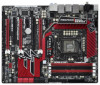
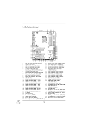
1.6 Motherboard Layout 1 2 24.4cm (9.6 in) 34 56 7 PS2 Mouse PS2 ATX12V1 CHA_FAN3 30.5cm (12.0 in) CPU_FAN1 CPU_FAN2 Keyboard Clr CMOS Coaxial SPDIF Optical SPDIF... SATA2_4_5 SATA2_2_3 47 46 45 44 43 42 41 40 PCI1 CD1 Super I/O Dual GLAN PCIE3 CMOS Battery Fatal1ty PCIE4 P67 Professional PCI2 Front USB 3.0 1 HDMI_SPDIF1 HD_AUDIO1 1 IR1 SATA3 1 FLOPPY1 1 PCIE5 COM1 USB3_2_3 SATA3_M3_M4 SATA3_M1_M2 Intel P67 Dr. Debug USB6_7 1 USB8_9 1 USB10_11 FRONT_1394 1 USB12_13 CLRCMOS1 1 CHA_FAN2 CHA_FAN1 PWRBTN RSTBTN SPEAKER1 1 1 PLED1 PLED PWRBTN 1 1 1...
1.6 Motherboard Layout 1 2 24.4cm (9.6 in) 34 56 7 PS2 Mouse PS2 ATX12V1 CHA_FAN3 30.5cm (12.0 in) CPU_FAN1 CPU_FAN2 Keyboard Clr CMOS Coaxial SPDIF Optical SPDIF... SATA2_4_5 SATA2_2_3 47 46 45 44 43 42 41 40 PCI1 CD1 Super I/O Dual GLAN PCIE3 CMOS Battery Fatal1ty PCIE4 P67 Professional PCI2 Front USB 3.0 1 HDMI_SPDIF1 HD_AUDIO1 1 IR1 SATA3 1 FLOPPY1 1 PCIE5 COM1 USB3_2_3 SATA3_M3_M4 SATA3_M1_M2 Intel P67 Dr. Debug USB6_7 1 USB8_9 1 USB10_11 FRONT_1394 1 USB12_13 CLRCMOS1 1 CHA_FAN2 CHA_FAN1 PWRBTN RSTBTN SPEAKER1 1 1 PLED1 PLED PWRBTN 1 1 1...
User Manual
Page 17
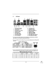
... 1.7 I/O Panel 1 2 3 45 6 7 10 8 11 9 12 20 19 18 17 1 PS/2 Mouse Port (Green) 2 Coaxial SPDIF Out Port * 3 LAN RJ-45 Port 4 Fatal1ty Mouse Port (USB4) 5 USB 2.0 Port (USB5) * 6 LAN RJ-45 Port 7 Side Speaker (Gray) 8 Rear Speaker (Black) 9 Central / Bass (Orange) 10 Line In (Light Blue...SPDIF Out Port 19 Clear CMOS Switch (CLRCBTN) 20 PS/2 Keyboard Port (Purple) * If you want to install USB 3.0 device on this motherboard, we recommend to use 2-channel speaker, please connect the speaker's plug into "Front Speaker Jack". TABLE for Audio Output Connection Audio Output Channels ...
... 1.7 I/O Panel 1 2 3 45 6 7 10 8 11 9 12 20 19 18 17 1 PS/2 Mouse Port (Green) 2 Coaxial SPDIF Out Port * 3 LAN RJ-45 Port 4 Fatal1ty Mouse Port (USB4) 5 USB 2.0 Port (USB5) * 6 LAN RJ-45 Port 7 Side Speaker (Gray) 8 Rear Speaker (Black) 9 Central / Bass (Orange) 10 Line In (Light Blue...SPDIF Out Port 19 Clear CMOS Switch (CLRCBTN) 20 PS/2 Keyboard Port (Purple) * If you want to install USB 3.0 device on this motherboard, we recommend to use 2-channel speaker, please connect the speaker's plug into "Front Speaker Jack". TABLE for Audio Output Connection Audio Output Channels ...
User Manual
Page 19
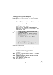
...or the power cord is an ATX form factor (12.0" x 9.6", 30.5 x 24.4 cm) motherboard. Chapter 2: Installation This is detached from the wall socket before you and damages to motherboard components. 2.1 Screw Holes Place screws into it. Unplug the power cord from the power supply. ...uninstall any component. 2. Also remember to ensure that comes with the component. Whenever you handle components. 3. To avoid damaging the motherboard components due to static electricity, NEVER place your chassis to use a grounded wrist strap or touch a safety grounded object before installing ...
...or the power cord is an ATX form factor (12.0" x 9.6", 30.5 x 24.4 cm) motherboard. Chapter 2: Installation This is detached from the wall socket before you and damages to motherboard components. 2.1 Screw Holes Place screws into it. Unplug the power cord from the power supply. ...uninstall any component. 2. Also remember to ensure that comes with the component. Whenever you handle components. 3. To avoid damaging the motherboard components due to static electricity, NEVER place your chassis to use a grounded wrist strap or touch a safety grounded object before installing ...
User Manual
Page 20
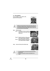
Otherwise, the CPU will be placed if returning the motherboard for after service. 20 Step 1. Step 1-2. Step 2. Step 1-3. It is found. Do not force to insert the CPU into the socket, please check if the ...
Otherwise, the CPU will be placed if returning the motherboard for after service. 20 Step 1. Step 1-2. Step 2. Step 1-3. It is found. Do not force to insert the CPU into the socket, please check if the ...

User Manual
Page 22
... fasteners. Rotate the fastener clockwise, then press down the fasteners without rotating them clockwise, the heatsink cannot be noticed that this motherboard supports Combo Cooler Option (C.C.O.), which provides the flexible option to adopt three different CPU cooler types, Socket LGA 775, LGA ...Then connect the CPU fan to the CPU_FAN connector (CPU_FAN1, see page 16, No. 4). 2.4 Installation of CPU Fan and Heatsink This motherboard is an example to illustrate the installation of the heatsink for Socket LGA 1155/1156 CPU fan. 22 Step 1. Apply Thermal Interface Material...
... fasteners. Rotate the fastener clockwise, then press down the fasteners without rotating them clockwise, the heatsink cannot be noticed that this motherboard supports Combo Cooler Option (C.C.O.), which provides the flexible option to adopt three different CPU cooler types, Socket LGA 775, LGA ...Then connect the CPU fan to the CPU_FAN connector (CPU_FAN1, see page 16, No. 4). 2.4 Installation of CPU Fan and Heatsink This motherboard is an example to illustrate the installation of the heatsink for Socket LGA 1155/1156 CPU fan. 22 Step 1. Apply Thermal Interface Material...
User Manual
Page 23
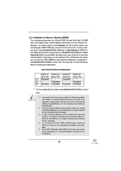
... configuration, and please install identical DDR3 DIMMs in the set of the same color. In other words, install them on this motherboard. 23 see p.16 No.6), so that Dual Channel Memory Technology can be damaged. 5. Populated (3)* Populated Populated Populated Populated * For the... configuration (3), please install identical DDR3 DIMMs in the DDR3 DIMM slots on this motherboard, it is not recommended to install them either in the set of memory modules in the same Dual Channel, for optimal compatibility and...
... configuration, and please install identical DDR3 DIMMs in the set of the same color. In other words, install them on this motherboard. 23 see p.16 No.6), so that Dual Channel Memory Technology can be damaged. 5. Populated (3)* Populated Populated Populated Populated * For the... configuration (3), please install identical DDR3 DIMMs in the DDR3 DIMM slots on this motherboard, it is not recommended to install them either in the set of memory modules in the same Dual Channel, for optimal compatibility and...
User Manual
Page 24
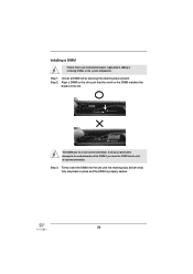
.... break notch notch break The DIMM only fits in place and the DIMM is properly seated. 24 Installing a DIMM Please make sure to the motherboard and the DIMM if you force the DIMM into the slot until the retaining clips at incorrect orientation. It will cause permanent damage to disconnect...
.... break notch notch break The DIMM only fits in place and the DIMM is properly seated. 24 Installing a DIMM Please make sure to the motherboard and the DIMM if you force the DIMM into the slot until the retaining clips at incorrect orientation. It will cause permanent damage to disconnect...
User Manual
Page 25
PCI slots: PCI slots are 2 PCI slots and 5 PCI Express slots on this motherboard. PCIE2 / PCIE4 (PCIE x16 slot; PCIE5 (PCIE x16 slot; Remove the system unit cover (if your motherboard is completely seated on /off or the power cord is used for PCI Express x16 lane width graphics ...cards, or used to install PCI Express graphics cards to motherboard chassis fan connector (CHA_FAN1, CHA_FAN2 or CHA_FAN3) when using multiple graphics cards for better thermal environment. 5. Step 4. Align the card connector ...
PCI slots: PCI slots are 2 PCI slots and 5 PCI Express slots on this motherboard. PCIE2 / PCIE4 (PCIE x16 slot; PCIE5 (PCIE x16 slot; Remove the system unit cover (if your motherboard is completely seated on /off or the power cord is used for PCI Express x16 lane width graphics ...cards, or used to install PCI Express graphics cards to motherboard chassis fan connector (CHA_FAN1, CHA_FAN2 or CHA_FAN3) when using multiple graphics cards for better thermal environment. 5. Step 4. Align the card connector ...
User Manual
Page 26
... to use NVIDIA® certified PSU. It is recommended to the PCI Express graphics cards. 26 2.7 SLITM and Quad SLITM Operation Guide This motherboard supports NVIDIA® SLITM and Quad SLITM (Scalable Link Interface) technology that your power supply unit (PSU) can provide at least the minimum power required...
... to use NVIDIA® certified PSU. It is recommended to the PCI Express graphics cards. 26 2.7 SLITM and Quad SLITM Operation Guide This motherboard supports NVIDIA® SLITM and Quad SLITM (Scalable Link Interface) technology that your power supply unit (PSU) can provide at least the minimum power required...
User Manual
Page 30
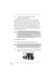
...they will operate as the example graphics card. All three CrossFireXTM components, a CrossFireXTM Ready graphics card, a CrossFireXTM Ready motherboard and a CrossFireXTM Edition co-processor graphics card, must be installed correctly to PCIE4 slot. Step 1. Combining a range ... while in the future, please refer to enable CrossFireXTM feature. 2.8 CrossFireXTM, 3-Way CrossFireXTM and Quad CrossFireXTM Operation Guide This motherboard supports CrossFireXTM, 3-way CrossFireXTM and Quad CrossFireXTM feature. Currently CrossFireXTM feature is supported with Windows® XP with Service Pack...
...they will operate as the example graphics card. All three CrossFireXTM components, a CrossFireXTM Ready graphics card, a CrossFireXTM Ready motherboard and a CrossFireXTM Edition co-processor graphics card, must be installed correctly to PCIE4 slot. Step 1. Combining a range ... while in the future, please refer to enable CrossFireXTM feature. 2.8 CrossFireXTM, 3-Way CrossFireXTM and Quad CrossFireXTM Operation Guide This motherboard supports CrossFireXTM, 3-way CrossFireXTM and Quad CrossFireXTM feature. Currently CrossFireXTM feature is supported with Windows® XP with Service Pack...
User Manual
Page 31
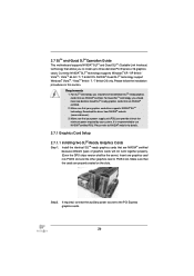
... the Radeon graphics card on the top of Radeon graphics cards. (CrossFire Bridge is provided with the graphics card you purchase, not bundled with this motherboard. Step 2. Please refer to D-Sub adapter.) 31 Connect two Radeon graphics cards by installing CrossFire Bridge on CrossFire Bridge Interconnects on PCIE2 slot. (You may...
... the Radeon graphics card on the top of Radeon graphics cards. (CrossFire Bridge is provided with the graphics card you purchase, not bundled with this motherboard. Step 2. Please refer to D-Sub adapter.) 31 Connect two Radeon graphics cards by installing CrossFire Bridge on CrossFire Bridge Interconnects on PCIE2 slot. (You may...
User Manual
Page 32
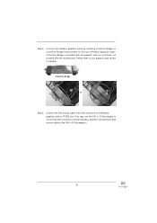
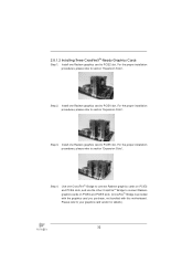
... Bridge to connect Radeon graphics cards on PCIE4 and PCIE5 slots. (CrossFireTM Bridge is provided with the graphics card you purchase, not bundled with this motherboard. 2.8.1.2 Installing Three CrossFireXTM-Ready Graphics Cards Step 1.
... Bridge to connect Radeon graphics cards on PCIE4 and PCIE5 slots. (CrossFireTM Bridge is provided with the graphics card you purchase, not bundled with this motherboard. 2.8.1.2 Installing Three CrossFireXTM-Ready Graphics Cards Step 1.
User Manual
Page 35
..., please refer to the document at the following path in "ATI Catalyst Control Center" is used only for updates and details. 2.9 Surround Display Feature This motherboard supports Surround Display upgrade. Step 7. After restarting your computer, please confirm whether the option "Enable CrossFireTM" in the Support CD: ..\ Surround Display Information...
..., please refer to the document at the following path in "ATI Catalyst Control Center" is used only for updates and details. 2.9 Surround Display Feature This motherboard supports Surround Display upgrade. Step 7. After restarting your computer, please confirm whether the option "Enable CrossFireTM" in the Support CD: ..\ Surround Display Information...


