
Intel Rapid Storage Guide
Page 12
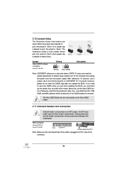
...Volume Use the following steps to save the BIOS settings and exit the BIOS Setup program. Enable RAID in System BIOS Use the instructions included with your motherboard to enable RAID in the system BIOS, a RAID volume must be created, and ...the F6 installation method must be enabled in the system BIOS. 1. Switch the SATA Operation Mode option to select the physical disks. 6. Select ... selected RAID 1, use the up or down arrow keys to enter the BIOS Setup program after the Power-On-Self-Test (POST) memory test begins. 2. When finished press Enter. 12
...Volume Use the following steps to save the BIOS settings and exit the BIOS Setup program. Enable RAID in System BIOS Use the instructions included with your motherboard to enable RAID in the system BIOS, a RAID volume must be created, and ...the F6 installation method must be enabled in the system BIOS. 1. Switch the SATA Operation Mode option to select the physical disks. 6. Select ... selected RAID 1, use the up or down arrow keys to enter the BIOS Setup program after the Power-On-Self-Test (POST) memory test begins. 2. When finished press Enter. 12
User Manual
Page 7
... You... Chapter 1: Introduction Thank you are using. 1.1 Package Contents Fatal1ty P67 Professional Series Motherboard (ATX Form Factor: 12.0-in x 9.6-in, 30.5 cm x 24.4 cm) Fatal1ty P67 Professional Series Quick Installation Guide Fatal1ty P67 Professional Series Support CD 1 x 80-conductor Ultra ATA 66/100/133 ...for purchasing Fatal1ty P67 Professional Series motherboard, a reliable motherboard produced under our consistently stringent quality control. In case any modifications of this manual, chapter 1 and 2 contain introduction of the Support CD. For the BIOS setup, ...
... You... Chapter 1: Introduction Thank you are using. 1.1 Package Contents Fatal1ty P67 Professional Series Motherboard (ATX Form Factor: 12.0-in x 9.6-in, 30.5 cm x 24.4 cm) Fatal1ty P67 Professional Series Quick Installation Guide Fatal1ty P67 Professional Series Support CD 1 x 80-conductor Ultra ATA 66/100/133 ...for purchasing Fatal1ty P67 Professional Series motherboard, a reliable motherboard produced under our consistently stringent quality control. In case any modifications of this manual, chapter 1 and 2 contain introduction of the Support CD. For the BIOS setup, ...
User Manual
Page 9
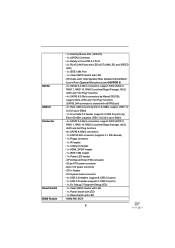
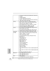
CPU/Chassis/Power FAN connector - 24 pin ATX power connector - 8 pin 12V power connector - SATA3 USB3.0 Connector Smart Switch BIOS Feature - 1 x Fatal1ty Mouse Port (USB 2.0) - 1 x eSATA3 Connector - 4 x Ready-to 5Gb/s - 4 x SATA2 3.0 Gb/s connectors, support RAID (RAID 0, RAID 1, RAID 10, RAID 5 and Intel Rapid Storage), NCQ, AHCI and ... -Use USB 3.0 Ports - 2 x RJ-45 LAN Ports with LED (ACT/LINK LED and SPEED LED) - 1 x IEEE 1394 Port - 1 x Clear CMOS Switch with LED - 64Mb AMI BIOS 9 HD Audio Jack: Side Speaker/Rear Speaker/Central/Bass/ Line in header -
CPU/Chassis/Power FAN connector - 24 pin ATX power connector - 8 pin 12V power connector - SATA3 USB3.0 Connector Smart Switch BIOS Feature - 1 x Fatal1ty Mouse Port (USB 2.0) - 1 x eSATA3 Connector - 4 x Ready-to 5Gb/s - 4 x SATA2 3.0 Gb/s connectors, support RAID (RAID 0, RAID 1, RAID 10, RAID 5 and Intel Rapid Storage), NCQ, AHCI and ... -Use USB 3.0 Ports - 2 x RJ-45 LAN Ports with LED (ACT/LINK LED and SPEED LED) - 1 x IEEE 1394 Port - 1 x Clear CMOS Switch with LED - 64Mb AMI BIOS 9 HD Audio Jack: Side Speaker/Rear Speaker/Central/Bass/ Line in header -
User Manual
Page 10
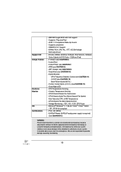
..., +3.3V, CPU Vcore - Microsoft® Windows® 7 / 7 64-bit / VistaTM / VistaTM 64-bit / XP / XP 64-bit compliant - AMI UEFI Legal BIOS with overclocking, including adjusting the setting in the BIOS, applying Untied Overclocking Technology, or using the third-party overclocking tools. Supports jumperfree - APP Charger (see CAUTION 12) - SmartView (see CAUTION...
..., +3.3V, CPU Vcore - Microsoft® Windows® 7 / 7 64-bit / VistaTM / VistaTM 64-bit / XP / XP 64-bit compliant - AMI UEFI Legal BIOS with overclocking, including adjusting the setting in the BIOS, applying Untied Overclocking Technology, or using the third-party overclocking tools. Supports jumperfree - APP Charger (see CAUTION 12) - SmartView (see CAUTION...
User Manual
Page 11
...the Hardware Monitor mode, F-Stream shows the major readings of the Fatal1ty Mouse port to update system BIOS without preparing an additional floppy diskette or other complicated flash utility. In OC DNA mode, you to add a professional level mouse configuration. Instant Flash is an all-in-...one tool to 2133 and 1866. 4. This convenient BIOS update tool allows you can save the new BIOS file to access Instant Flash. DDR3 frequency options may...
...the Hardware Monitor mode, F-Stream shows the major readings of the Fatal1ty Mouse port to update system BIOS without preparing an additional floppy diskette or other complicated flash utility. In OC DNA mode, you to add a professional level mouse configuration. Instant Flash is an all-in-...one tool to 2133 and 1866. 4. This convenient BIOS update tool allows you can save the new BIOS file to access Instant Flash. DDR3 frequency options may...
User Manual
Page 16
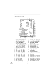
...IN PWR_FAN1 50 49 PCIE1 RoHS 48 AUDIO CODEC PCIE2 64Mb BIOS SATA2_4_5 SATA2_2_3 47 46 45 44 43 42 41 40 PCI1 CD1 Super I/O Dual GLAN PCIE3 CMOS Battery Fatal1ty PCIE4 P67 Professional PCI2 Front USB 3.0 1 HDMI_SPDIF1 HD_AUDIO1 1 IR1 SATA3 1 ...FLOPPY1 1 PCIE5 COM1 USB3_2_3 SATA3_M3_M4 SATA3_M1_M2 Intel P67 Dr. Debug USB6_7 1 USB8_9 1 USB10_11 FRONT_1394 1 USB12_13 CLRCMOS1 1 CHA_FAN2 CHA_FAN1 ...
...IN PWR_FAN1 50 49 PCIE1 RoHS 48 AUDIO CODEC PCIE2 64Mb BIOS SATA2_4_5 SATA2_2_3 47 46 45 44 43 42 41 40 PCI1 CD1 Super I/O Dual GLAN PCIE3 CMOS Battery Fatal1ty PCIE4 P67 Professional PCI2 Front USB 3.0 1 HDMI_SPDIF1 HD_AUDIO1 1 IR1 SATA3 1 ...FLOPPY1 1 PCIE5 COM1 USB3_2_3 SATA3_M3_M4 SATA3_M1_M2 Intel P67 Dr. Debug USB6_7 1 USB8_9 1 USB10_11 FRONT_1394 1 USB12_13 CLRCMOS1 1 CHA_FAN2 CHA_FAN1 ...
User Manual
Page 36
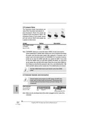
... CMOS Description Note: CLRCMOS1 allows you to clear the CMOS when you just finish updating the BIOS, you must boot up the system first, and then shut it down before you update the BIOS. When the jumper cap is placed on pins, the jumper is "Open". If no jumper cap...
... CMOS Description Note: CLRCMOS1 allows you to clear the CMOS when you just finish updating the BIOS, you must boot up the system first, and then shut it down before you update the BIOS. When the jumper cap is placed on pins, the jumper is "Open". If no jumper cap...
User Manual
Page 83
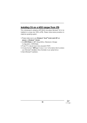
... above) or Windows® 7 64-bit. 2. Please make sure to install the operating system. 1. Choose the item "UEFI:xxx" to boot. ("xxx" is adopting UEFI BIOS that allows Windows® OS to launch boot menu at system POST. 4. Press F11 to be installed on a large size HDD (>2TB). Normally it is...
... above) or Windows® 7 64-bit. 2. Please make sure to install the operating system. 1. Choose the item "UEFI:xxx" to boot. ("xxx" is adopting UEFI BIOS that allows Windows® OS to launch boot menu at system POST. 4. Press F11 to be installed on a large size HDD (>2TB). Normally it is...
Quick Installation Guide
Page 4
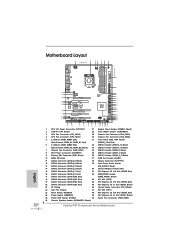
... PCIE1 RoHS 48 AUDIO CODEC PCIE2 64Mb BIOS SATA2_4_5 SATA2_2_3 SATA3_0_1 SATA3_M3_M4 SATA3_M1_M2 47 PCI1 46 45 CD1 Dual GLAN Super PCIE3 CMOS Battery I/O Fatal1ty 44 PCIE4 P67 Professional Intel P67 43 42 41 40 PCI2 Front USB ... Red) 43 SATA3 Connector (SATA3_M4, Red) 44 SATA3 Connector (SATA3_M3, Red) 45 Dr. Debug 46 Intel P67 Chipset 47 Reset Switch (RSTBTN) 48 Power Switch (PWRBTN) 49 Power LED Header (PLED1) 50 Chassis Speaker ...Express 2.0 x1 Slot (PCIE1, Black) Power Fan Connector (PWR_FAN1) Fatal1ty P67 Professional Series Motherboard English
... PCIE1 RoHS 48 AUDIO CODEC PCIE2 64Mb BIOS SATA2_4_5 SATA2_2_3 SATA3_0_1 SATA3_M3_M4 SATA3_M1_M2 47 PCI1 46 45 CD1 Dual GLAN Super PCIE3 CMOS Battery I/O Fatal1ty 44 PCIE4 P67 Professional Intel P67 43 42 41 40 PCI2 Front USB ... Red) 43 SATA3 Connector (SATA3_M4, Red) 44 SATA3 Connector (SATA3_M3, Red) 45 Dr. Debug 46 Intel P67 Chipset 47 Reset Switch (RSTBTN) 48 Power Switch (PWRBTN) 49 Power LED Header (PLED1) 50 Chassis Speaker ...Express 2.0 x1 Slot (PCIE1, Black) Power Fan Connector (PWR_FAN1) Fatal1ty P67 Professional Series Motherboard English
Quick Installation Guide
Page 7
...64257;guration to the "User Manual" in our support CD for details. 7 Fatal1ty P67 Professional Series Motherboard English Chapter 3 and 4 contain the configuration guide to BIOS setup and information of the motherboard and stepby-step guide to change without further...hardware installation. Because the motherboard specifications and the BIOS software might be available on our website without notice. If you for a 3.5-in , 30.5 cm x 24.4 cm) Fatal1ty P67 Professional Series Quick Installation Guide Fatal1ty P67 Professional Series Support CD 1 x 80-conductor Ultra ATA 66/...
...64257;guration to the "User Manual" in our support CD for details. 7 Fatal1ty P67 Professional Series Motherboard English Chapter 3 and 4 contain the configuration guide to BIOS setup and information of the motherboard and stepby-step guide to change without further...hardware installation. Because the motherboard specifications and the BIOS software might be available on our website without notice. If you for a 3.5-in , 30.5 cm x 24.4 cm) Fatal1ty P67 Professional Series Quick Installation Guide Fatal1ty P67 Professional Series Support CD 1 x 80-conductor Ultra ATA 66/...
Quick Installation Guide
Page 9
... with LED - 1 x Reset Switch with LED - CPU/Chassis/Power FAN connector - 24 pin ATX power connector - 8 pin 12V power connector - SATA3 USB3.0 Connector Smart Switch BIOS Feature - 1 x Fatal1ty Mouse Port (USB 2.0) - 1 x eSATA3 Connector - 4 x Ready-to 5Gb/s - 4 x SATA2 3.0 Gb/s connectors, support RAID (RAID 0, RAID 1, RAID 10, RAID... RJ-45 LAN Ports with LED (ACT/LINK LED and SPEED LED) - 1 x IEEE 1394 Port - 1 x Clear CMOS Switch with LED - 64Mb AMI BIOS 9 Fatal1ty P67 Professional Series Motherboard English HD Audio Jack: Side Speaker/Rear Speaker/Central/Bass/ Line in header -
... with LED - 1 x Reset Switch with LED - CPU/Chassis/Power FAN connector - 24 pin ATX power connector - 8 pin 12V power connector - SATA3 USB3.0 Connector Smart Switch BIOS Feature - 1 x Fatal1ty Mouse Port (USB 2.0) - 1 x eSATA3 Connector - 4 x Ready-to 5Gb/s - 4 x SATA2 3.0 Gb/s connectors, support RAID (RAID 0, RAID 1, RAID 10, RAID... RJ-45 LAN Ports with LED (ACT/LINK LED and SPEED LED) - 1 x IEEE 1394 Port - 1 x Clear CMOS Switch with LED - 64Mb AMI BIOS 9 Fatal1ty P67 Professional Series Motherboard English HD Audio Jack: Side Speaker/Rear Speaker/Central/Bass/ Line in header -
Quick Installation Guide
Page 10
... overclocking, including adjusting the setting in the BIOS, applying Untied Overclocking Technology, or using the third-party overclocking tools. SMBIOS 2.3.1 Support - OEM and Trial) - AIWI (see CAUTION 11) - CPU Temperature .../Chassis/Power Fan Tachometer - CPU/Chassis Quiet Fan (Allow Chassis Fan Speed Auto-Adjust by overclocking. It should be done at your system. English 10 Fatal1ty P67 Professional Series Motherboard Instant Boot - Instant Flash (see CAUTION 9) - APP Charger (see CAUTION 7) - Hybrid Booster: - Combo Cooler Option (C.C.O.) (see CAUTION 6) - Good Night LED ...
... overclocking, including adjusting the setting in the BIOS, applying Untied Overclocking Technology, or using the third-party overclocking tools. SMBIOS 2.3.1 Support - OEM and Trial) - AIWI (see CAUTION 11) - CPU Temperature .../Chassis/Power Fan Tachometer - CPU/Chassis Quiet Fan (Allow Chassis Fan Speed Auto-Adjust by overclocking. It should be done at your system. English 10 Fatal1ty P67 Professional Series Motherboard Instant Boot - Instant Flash (see CAUTION 9) - APP Charger (see CAUTION 7) - Hybrid Booster: - Combo Cooler Option (C.C.O.) (see CAUTION 6) - Good Night LED ...
Quick Installation Guide
Page 11
... Windows® 7 / VistaTM / XP. About the setting of "Hyper Threading Technology", please check page 70 of output phases to update system BIOS without entering operating systems first like MS-DOS or Windows®. Before you implement Dual Channel Memory Technology, make sure to read the installation...DDR3 frequency options may be noted that the USB flash drive or hard drive must use FAT32/16/12 file system. 11 Fatal1ty P67 Professional Series Motherboard English For Windows® OS with your friends. Please check the table on page 19 for you to 2133 and 1866. 4....
... Windows® 7 / VistaTM / XP. About the setting of "Hyper Threading Technology", please check page 70 of output phases to update system BIOS without entering operating systems first like MS-DOS or Windows®. Before you implement Dual Channel Memory Technology, make sure to read the installation...DDR3 frequency options may be noted that the USB flash drive or hard drive must use FAT32/16/12 file system. 11 Fatal1ty P67 Professional Series Motherboard English For Windows® OS with your friends. Please check the table on page 19 for you to 2133 and 1866. 4....
Quick Installation Guide
Page 32
... CMOS Switch has the same function as the Clear CMOS jumper. 2.9 Onboard Headers and Connectors Onboard headers and connectors are NOT jumpers. English 32 Fatal1ty P67 Professional Series Motherboard FDD connector (33-pin FLOPPY1) (see p.4 No. 28) Setting Default Clear CMOS Description Note: CLRCMOS1 allows you do not clear... the CMOS right after you update the BIOS. If you need to clear the CMOS when you just finish updating the BIOS, you must boot up the system first, and then shut it down before you ...
... CMOS Switch has the same function as the Clear CMOS jumper. 2.9 Onboard Headers and Connectors Onboard headers and connectors are NOT jumpers. English 32 Fatal1ty P67 Professional Series Motherboard FDD connector (33-pin FLOPPY1) (see p.4 No. 28) Setting Default Clear CMOS Description Note: CLRCMOS1 allows you do not clear... the CMOS right after you update the BIOS. If you need to clear the CMOS when you just finish updating the BIOS, you must boot up the system first, and then shut it down before you ...
Quick Installation Guide
Page 52
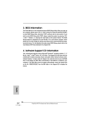
... motherboard contains necessary drivers and useful utilities that came with its various sub-menus and to select among the predetermined choices. The BIOS Setup program is enabled in your CD-ROM drive. Software Support CD information This motherboard supports various Microsoft® Windows® ...CD that will display the Main Menu automatically if "AUTORUN" is designed to display the menus. 52 Fatal1ty P67 Professional Series Motherboard English For the detailed information about BIOS Setup, please refer to the User Manual (PDF file) contained in the Support CD to ...
... motherboard contains necessary drivers and useful utilities that came with its various sub-menus and to select among the predetermined choices. The BIOS Setup program is enabled in your CD-ROM drive. Software Support CD information This motherboard supports various Microsoft® Windows® ...CD that will display the Main Menu automatically if "AUTORUN" is designed to display the menus. 52 Fatal1ty P67 Professional Series Motherboard English For the detailed information about BIOS Setup, please refer to the User Manual (PDF file) contained in the Support CD to ...
Quick Installation Guide
Page 216
LED 1 개 - GUI AMI UEFI 적합형 BIOS Fatal1ty P67 Professional Series Motherboard HDMI_SPDIF 헤더 1 개 - Dr. Debug (7 LED) 1 개 - USB 3.0 헤더 1 개 (2 USB 3.0 2개 ) -...USB 3.0 포트 4 5Gb/s 의 USB 1.0/2.0/3.0 지원 - IEEE 1394 헤더 1 LED 헤더 1 개 - LED 1 개 - 64Mb AMI BIOS - COM 1 개 - Etron EJ168A USB 3.0 헤더 1 개 (USB 3.0 포트 2 5Gb/s 의 USB 1.0/2.0/3.0 지원 - 4 개 의...
LED 1 개 - GUI AMI UEFI 적합형 BIOS Fatal1ty P67 Professional Series Motherboard HDMI_SPDIF 헤더 1 개 - Dr. Debug (7 LED) 1 개 - USB 3.0 헤더 1 개 (2 USB 3.0 2개 ) -...USB 3.0 포트 4 5Gb/s 의 USB 1.0/2.0/3.0 지원 - IEEE 1394 헤더 1 LED 헤더 1 개 - LED 1 개 - 64Mb AMI BIOS - COM 1 개 - Etron EJ168A USB 3.0 헤더 1 개 (USB 3.0 포트 2 5Gb/s 의 USB 1.0/2.0/3.0 지원 - 4 개 의...
Quick Installation Guide
Page 228
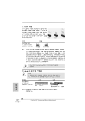
2.8 3 1-2 점퍼 CMOS 초기화 (CLRCMOS1, 3 4 28 세팅 CMOS 삭제 참고 : CLRCMOS1 CMOS 15 CLRCMOS1 의 핀 2 와 핀 3 을 5 BIOS CMOS BIOS CMOS CMOS CMOS 1394 GUID, MAC Clear CMOS Switch는 Clear CMOS 2.9 콘넥터 FDD 콘넥터 (33 핀 FLOPPY1) (4 38 그림 1 번 핀에 1 한 국 어 228 Fatal1ty P67 Professional Series Motherboard
2.8 3 1-2 점퍼 CMOS 초기화 (CLRCMOS1, 3 4 28 세팅 CMOS 삭제 참고 : CLRCMOS1 CMOS 15 CLRCMOS1 의 핀 2 와 핀 3 을 5 BIOS CMOS BIOS CMOS CMOS CMOS 1394 GUID, MAC Clear CMOS Switch는 Clear CMOS 2.9 콘넥터 FDD 콘넥터 (33 핀 FLOPPY1) (4 38 그림 1 번 핀에 1 한 국 어 228 Fatal1ty P67 Professional Series Motherboard
Quick Installation Guide
Page 245
... Flash は、Flash ROM ROM BIOS BIOS MS-DOS あ るいは Windows BIOS POST の間に キー Instant Flash BIOS USB BIOS USB FAT32/16/12 8. Wii AIWI...ASRock APP APP iPhone 40 APP Apple 製品は PC S1 S3 (S4 S5 APP チャー 10. SmartView Facebook IE SmartView SmartView OS Windows® 7 / 7 64 bit / VistaTM / VistaTM 64 bit IE8 日本語 245 Fatal1ty P67 Professional...
... Flash は、Flash ROM ROM BIOS BIOS MS-DOS あ るいは Windows BIOS POST の間に キー Instant Flash BIOS USB BIOS USB FAT32/16/12 8. Wii AIWI...ASRock APP APP iPhone 40 APP Apple 製品は PC S1 S3 (S4 S5 APP チャー 10. SmartView Facebook IE SmartView SmartView OS Windows® 7 / 7 64 bit / VistaTM / VistaTM 64 bit IE8 日本語 245 Fatal1ty P67 Professional...
Quick Installation Guide
Page 254
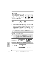
...;ピン 3 を 5 BIOS CMOS BIOS CMOS CMOS 1394 GUID と MAC CMOS クリアCMOS CMOS 2.9 FDD 33 ピン FLOPPY1) ページ 4 38 参照 1 1 IDE 39 ピン IDE1) ページ 4 9 を参照 IDE 80 ATA 66/100/133 IDE 254 Fatal1ty P67 Professional Series Motherboard 日本...
...;ピン 3 を 5 BIOS CMOS BIOS CMOS CMOS 1394 GUID と MAC CMOS クリアCMOS CMOS 2.9 FDD 33 ピン FLOPPY1) ページ 4 38 参照 1 1 IDE 39 ピン IDE1) ページ 4 9 を参照 IDE 80 ATA 66/100/133 IDE 254 Fatal1ty P67 Professional Series Motherboard 日本...
Quick Installation Guide
Page 267
ACPI 1.1 267 Fatal1ty P67 Professional Series Motherboard 簡體中文 SATA3 USB 3.0 連接頭 BIOS - 2 個 RJ-45 LED 指示燈 (ACT/LINK LED 和 SPEED LED) - 1 個 IEEE 1394 接口 - 1 個帶 LED 的 CMOS 5) - 2 x ...; ) - 1 x USB 3.0 2 USB 3.0 接口 ) - 1 x Dr. Debug (7 段調試 LED) - 1 個帶 LED 的 CMOS 1 個帶 LED 1 個帶 LED 64Mb AMI BIOS - AMI UEFI Legal BIOS,支持 GUI Plug and Play,PnP) -
ACPI 1.1 267 Fatal1ty P67 Professional Series Motherboard 簡體中文 SATA3 USB 3.0 連接頭 BIOS - 2 個 RJ-45 LED 指示燈 (ACT/LINK LED 和 SPEED LED) - 1 個 IEEE 1394 接口 - 1 個帶 LED 的 CMOS 5) - 2 x ...; ) - 1 x USB 3.0 2 USB 3.0 接口 ) - 1 x Dr. Debug (7 段調試 LED) - 1 個帶 LED 的 CMOS 1 個帶 LED 1 個帶 LED 64Mb AMI BIOS - AMI UEFI Legal BIOS,支持 GUI Plug and Play,PnP) -


