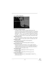
Intel Rapid Storage Guide
Page 13
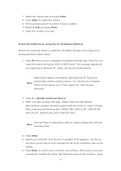
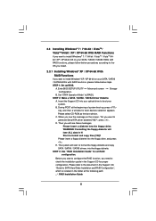
... after pressing F6. Select your controller from the list of Windows XP* setup (during operating system setup: 1. Install the RAID Driver Using the F6 Installation Method Perform the following files: IAAHCI.INF, IAAHCI.CAT, IASTOR.INF, IASTOR.CAT, IASTOR.SYS, and TXTSETUP.OEM. Select the volume size and press Enter. 8. Press Enter to confirm your exit. Use the Floppy Configuration Utility to create a floppy disk with a screen asking you see a prompt that...
... after pressing F6. Select your controller from the list of Windows XP* setup (during operating system setup: 1. Install the RAID Driver Using the F6 Installation Method Perform the following files: IAAHCI.INF, IAAHCI.CAT, IASTOR.INF, IASTOR.CAT, IASTOR.SYS, and TXTSETUP.OEM. Select the volume size and press Enter. 8. Press Enter to confirm your exit. Use the Floppy Configuration Utility to create a floppy disk with a screen asking you see a prompt that...

User Manual
Page 11
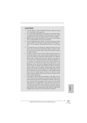
... configuration. In Fan Control mode, F-Stream shows the fan speed and temperature for proper connection. 6. F-Stream is no such limitation. 5. This motherboard supports Dual Channel Memory Technology. DDR3 frequency options may be noted that the USB flash drive or hard drive must use FAT32/16/12 file system. 11 In IES (Intelligent Energy Saver) mode, the voltage regulator can update your system. This convenient BIOS update tool allows you to fi...
... configuration. In Fan Control mode, F-Stream shows the fan speed and temperature for proper connection. 6. F-Stream is no such limitation. 5. This motherboard supports Dual Channel Memory Technology. DDR3 frequency options may be noted that the USB flash drive or hard drive must use FAT32/16/12 file system. 11 In IES (Intelligent Energy Saver) mode, the voltage regulator can update your system. This convenient BIOS update tool allows you to fi...

User Manual
Page 13
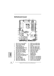
...-pin DDR3 DIMM Slots 27 USB 2.0 Header (USB8_9, Black) (Dual Channel: DDR3_A2, DDR3_B2, Black) 28 Chassis Fan Connector (CHA_FAN1) 7 ATX Power Connector (ATXPWR1) 29 Infrared Module Header (IR1) 8 Primary IDE Connector (IDE1, Black) 30 Floppy Connector (FLOPPY1) 9 Clear CMOS Jumper (CLRCMOS1) 31 COM Port Header (COM1) 10 Chassis Fan Connector (CHA_FAN2) 32 Front Panel Audio Header 11 64Mb SPI Flash (HD_AUDIO1, Black) 12 Power LED Header (PLED1) 33 HDMI_SPDIF Header 13 Chassis Speaker Header (SPEAKER 1, Black) (HDMI_SPDIF1, Black) 14 System Panel Header (PANEL1, Black) 34 PCI...
...-pin DDR3 DIMM Slots 27 USB 2.0 Header (USB8_9, Black) (Dual Channel: DDR3_A2, DDR3_B2, Black) 28 Chassis Fan Connector (CHA_FAN1) 7 ATX Power Connector (ATXPWR1) 29 Infrared Module Header (IR1) 8 Primary IDE Connector (IDE1, Black) 30 Floppy Connector (FLOPPY1) 9 Clear CMOS Jumper (CLRCMOS1) 31 COM Port Header (COM1) 10 Chassis Fan Connector (CHA_FAN2) 32 Front Panel Audio Header 11 64Mb SPI Flash (HD_AUDIO1, Black) 12 Power LED Header (PLED1) 33 HDMI_SPDIF Header 13 Chassis Speaker Header (SPEAKER 1, Black) (HDMI_SPDIF1, Black) 14 System Panel Header (PANEL1, Black) 34 PCI...
User Manual
Page 30
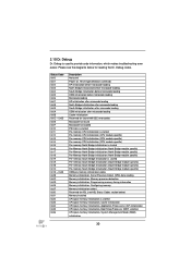
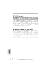
... 0x2C 0x2D 0x2E 0x2F 0x30 0x31 0x32 0x33 0x34 0x35 0x36 Description Not used to provide code information, which makes troubleshooting even easier. 2.10 Dr. Debug Dr. Debug is used Power on. Please see ASL Status Codes section below for ASL (see the diagrams below ) Memory Installed CPU post-memory initialization is started CPU post-memory initialization. Boot Strap Processor (BSP) selection CPU post-memory initialization. System Management Mode (SMM) initialization 30
... 0x2C 0x2D 0x2E 0x2F 0x30 0x31 0x32 0x33 0x34 0x35 0x36 Description Not used to provide code information, which makes troubleshooting even easier. 2.10 Dr. Debug Dr. Debug is used Power on. Please see ASL Status Codes section below for ASL (see the diagrams below ) Memory Installed CPU post-memory initialization is started CPU post-memory initialization. Boot Strap Processor (BSP) selection CPU post-memory initialization. System Management Mode (SMM) initialization 30
User Manual
Page 33
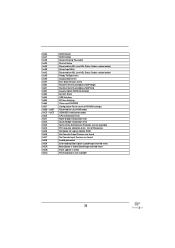
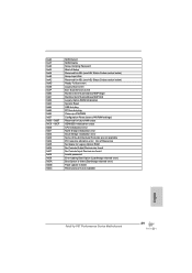
... Codes section below) Setup Input Wait Reserved for ASL (see ASL Status Codes section below) Ready To Boot event Legacy Boot event Exit Boot Services event Runtime Set Virtual Address MAP Begin Runtime Set Virtual Address MAP End Legacy Option ROM Initialization System Reset USB hot plug PCI bus hot plug Clean-up of NVRAM Configuration Reset (reset of the Architectural Protocols are found Invalid password Error loading Boot Option (LoadImage returned error) Boot Option is failed (StartImage returned error) Flash update...
... Codes section below) Setup Input Wait Reserved for ASL (see ASL Status Codes section below) Ready To Boot event Legacy Boot event Exit Boot Services event Runtime Set Virtual Address MAP Begin Runtime Set Virtual Address MAP End Legacy Option ROM Initialization System Reset USB hot plug PCI bus hot plug Clean-up of NVRAM Configuration Reset (reset of the Architectural Protocols are found Invalid password Error loading Boot Option (LoadImage returned error) Boot Option is failed (StartImage returned error) Flash update...
User Manual
Page 38
.... Set the option "SATA Mode" to format and copy files [YN]? A. Then you want to install Windows® XP / XP 64-bit on the support CD driver page. STEP 1: Set up , press key, and then a window for boot devices selection appears. D. Formatting the floppy diskette will start to format the floppy diskette and copy SATA / SATAII / SATA3 drivers into the floppy drive. Start to [RAID]. Enter UEFI SETUP UTILITY Advanced screen Storage...
.... Set the option "SATA Mode" to format and copy files [YN]? A. Then you want to install Windows® XP / XP 64-bit on the support CD driver page. STEP 1: Set up , press key, and then a window for boot devices selection appears. D. Formatting the floppy diskette will start to format the floppy diskette and copy SATA / SATAII / SATA3 drivers into the floppy drive. Start to [RAID]. Enter UEFI SETUP UTILITY Advanced screen Storage...
User Manual
Page 39
...;oppy disk, the driver will be installed to RAID 0, RAID 1 or RAID 5 at a later date by booting from the Support CD again so that "Intel Rapid Storage" will be presented. After the installation of Windows® setup, press F6 to install a thirdparty RAID driver. The following path: .. \ RAID Installation Guide STEP 4: Install Windows® XP / XP 64-bit OS on your system. After making a SATA / SATAII / SATA3 driver diskette and using RAID migration feature of Windows setup...
...;oppy disk, the driver will be installed to RAID 0, RAID 1 or RAID 5 at a later date by booting from the Support CD again so that "Intel Rapid Storage" will be presented. After the installation of Windows® setup, press F6 to install a thirdparty RAID driver. The following path: .. \ RAID Installation Guide STEP 4: Install Windows® XP / XP 64-bit OS on your system. After making a SATA / SATAII / SATA3 driver diskette and using RAID migration feature of Windows setup...
User Manual
Page 40
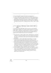
5. This will install the necessary Intel Storage Utility and start menu links. 3. Open the Intel Storage Utility from the Start Menu and select "Create RAID volume from Existing Hard Drive" from the Internet. Once the migration is complete, reboot the system. Finish the Windows® installation and install all necessary drivers. 6. Boot Windows®, install the Intel(R) Rapid Storage software, if not already installed, using the setup package obtained from a CD-ROM or from the Actions...
5. This will install the necessary Intel Storage Utility and start menu links. 3. Open the Intel Storage Utility from the Start Menu and select "Create RAID volume from Existing Hard Drive" from the Internet. Once the migration is complete, reboot the system. Finish the Windows® installation and install all necessary drivers. 6. Boot Windows®, install the Intel(R) Rapid Storage software, if not already installed, using the setup package obtained from a CD-ROM or from the Actions...
User Manual
Page 41
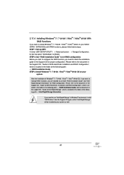
...: .. \ RAID Installation Guide and the document in the support CD, "Guide to Intel Rapid Storage", which is located in Windows® environment, install "SATAII driver" from the Support CD again so that "Intel Rapid Storage" will be installed to your system as well. 41 STEP 1: Set up UEFI. Enter UEFI SETUP UTILITY Advanced screen Storage Configuration. Set the option "SATA Mode" to set RAID configuration. After the installation of Windows® 7 / 7 64-bit / VistaTM / VistaTM 64-bit...
...: .. \ RAID Installation Guide and the document in the support CD, "Guide to Intel Rapid Storage", which is located in Windows® environment, install "SATAII driver" from the Support CD again so that "Intel Rapid Storage" will be installed to your system as well. 41 STEP 1: Set up UEFI. Enter UEFI SETUP UTILITY Advanced screen Storage Configuration. Set the option "SATA Mode" to set RAID configuration. After the installation of Windows® 7 / 7 64-bit / VistaTM / VistaTM 64-bit...
User Manual
Page 51
... default value is supported through the native processor instructions HLT and MWAIT and requires no hardware support from the chipset. In the C1 power state, the processor maintains the context of the system caches. CPU C6 State Support Use this technology, such as Microsoft® Windows® XP / VistaTM / 7. Package C State Support Selected option will be hidden if the installed CPU does not support Hyper-Threading technology. This option will...
... default value is supported through the native processor instructions HLT and MWAIT and requires no hardware support from the chipset. In the C1 power state, the processor maintains the context of the system caches. CPU C6 State Support Use this technology, such as Microsoft® Windows® XP / VistaTM / 7. Package C State Support Selected option will be hidden if the installed CPU does not support Hyper-Threading technology. This option will...

User Manual
Page 59
...item to enable or disable the use of USB 3.0 controller. Enables support for the details of these four options: [Enabled] - Enables legacy support if USB devices are not allowed to use only under legacy OS and UEFI setup when [Disabled] is recommended to select [Disabled] to enable or disable legacy support for USB devices. USB devices are four configuration options: [Enabled], [Auto], [Disabled] and [UEFI Setup Only]. Legacy USB Support Use this option to enter OS. [UEFI Setup Only] - Legacy USB 3.0 Support Use this option to use under UEFI setup and Windows...
...item to enable or disable the use of USB 3.0 controller. Enables support for the details of these four options: [Enabled] - Enables legacy support if USB devices are not allowed to use only under legacy OS and UEFI setup when [Disabled] is recommended to select [Disabled] to enable or disable legacy support for USB devices. USB devices are four configuration options: [Enabled], [Auto], [Disabled] and [UEFI Setup Only]. Legacy USB Support Use this option to enter OS. [UEFI Setup Only] - Legacy USB 3.0 Support Use this option to use under UEFI setup and Windows...
User Manual
Page 64
Because motherboard settings and hardware options vary, use the setup procedures in the Support CD to display the menus. 4.2.2 Drivers Menu The Drivers Menu shows the available devices drivers if the system detects installed devices. Please install the necessary drivers to your computer. If the Main Menu did not appear automatically, locate and double click on a specific item then follow the installation wizard to visit our website; or you need to...
Because motherboard settings and hardware options vary, use the setup procedures in the Support CD to display the menus. 4.2.2 Drivers Menu The Drivers Menu shows the available devices drivers if the system detects installed devices. Please install the necessary drivers to your computer. If the Main Menu did not appear automatically, locate and double click on a specific item then follow the installation wizard to visit our website; or you need to...
Quick Installation Guide
Page 4
...-pin DDR3 DIMM Slots 27 USB 2.0 Header (USB8_9, Black) (Dual Channel: DDR3_A2, DDR3_B2, Black) 28 Chassis Fan Connector (CHA_FAN1) 7 ATX Power Connector (ATXPWR1) 29 Infrared Module Header (IR1) 8 Primary IDE Connector (IDE1, Black) 30 Floppy Connector (FLOPPY1) 9 Clear CMOS Jumper (CLRCMOS1) 31 COM Port Header (COM1) 10 Chassis Fan Connector (CHA_FAN2) 32 Front Panel Audio Header 11 64Mb SPI Flash (HD_AUDIO1, Black) 12 Power LED Header (PLED1) 33 HDMI_SPDIF Header 13 Chassis Speaker Header (SPEAKER 1, Black) (HDMI_SPDIF1, Black) 14 System Panel Header (PANEL1, Black) 34 PCI...
...-pin DDR3 DIMM Slots 27 USB 2.0 Header (USB8_9, Black) (Dual Channel: DDR3_A2, DDR3_B2, Black) 28 Chassis Fan Connector (CHA_FAN1) 7 ATX Power Connector (ATXPWR1) 29 Infrared Module Header (IR1) 8 Primary IDE Connector (IDE1, Black) 30 Floppy Connector (FLOPPY1) 9 Clear CMOS Jumper (CLRCMOS1) 31 COM Port Header (COM1) 10 Chassis Fan Connector (CHA_FAN2) 32 Front Panel Audio Header 11 64Mb SPI Flash (HD_AUDIO1, Black) 12 Power LED Header (PLED1) 33 HDMI_SPDIF Header 13 Chassis Speaker Header (SPEAKER 1, Black) (HDMI_SPDIF1, Black) 14 System Panel Header (PANEL1, Black) 34 PCI...
Quick Installation Guide
Page 5
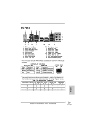
... 12 ** 10 11 12 13 14 *** 15 16 17 18 Front Speaker (Lime) Microphone (Pink) USB 2.0 Ports (USB01) USB 3.0 Ports (USB23) USB 2.0 Ports (USB45) eSATA3 Connector (eSATA3) Optical SPDIF Out Port Clear CMOS Switch (CLRCBTN) PS/2 Keyboard Port (Purple) * There are two LED next to the table below for Audio Output Connection Audio Output Channels Front Speaker Rear Speaker Central / Bass Side Speaker (No. 10) (No. 7) (No. 8) (No. 6) 2 V -- -- -- 4 V V -- -- 6 V V V -- 8 V V V V English 5 Fatal1ty P67 Performance Series Motherboard Please refer to the LAN port.
... 12 ** 10 11 12 13 14 *** 15 16 17 18 Front Speaker (Lime) Microphone (Pink) USB 2.0 Ports (USB01) USB 3.0 Ports (USB23) USB 2.0 Ports (USB45) eSATA3 Connector (eSATA3) Optical SPDIF Out Port Clear CMOS Switch (CLRCBTN) PS/2 Keyboard Port (Purple) * There are two LED next to the table below for Audio Output Connection Audio Output Channels Front Speaker Rear Speaker Central / Bass Side Speaker (No. 10) (No. 7) (No. 8) (No. 6) 2 V -- -- -- 4 V V -- -- 6 V V V -- 8 V V V V English 5 Fatal1ty P67 Performance Series Motherboard Please refer to the LAN port.

Quick Installation Guide
Page 9
... RAID 1, RAID 10, RAID 5 and Intel Rapid Storage), NCQ, AHCI and Hot Plug functions - 2 x SATA3 6.0Gb/s connectors - 1 x ATA133 IDE connector (supports 2 x IDE devices) - 1 x Floppy connector - 1 x IR header - 1 x COM port header - 1 x HDMI_SPDIF header - 1 x Power LED header - ACPI 1.1 Compliance Wake Up Events - Creative Sound Blaster X-Fi MB - OEM and Trial; CPU/Chassis/Power FAN connector - 24 pin ATX power connector - 8 pin 12V power connector - Front panel audio connector - 3 x USB 2.0 headers (support 6 USB 2.0 ports) - 1 x Dr. Debug (7-Segment Debug LED) - 1 x Clear CMOS Switch...
... RAID 1, RAID 10, RAID 5 and Intel Rapid Storage), NCQ, AHCI and Hot Plug functions - 2 x SATA3 6.0Gb/s connectors - 1 x ATA133 IDE connector (supports 2 x IDE devices) - 1 x Floppy connector - 1 x IR header - 1 x COM port header - 1 x HDMI_SPDIF header - 1 x Power LED header - ACPI 1.1 Compliance Wake Up Events - Creative Sound Blaster X-Fi MB - OEM and Trial; CPU/Chassis/Power FAN connector - 24 pin ATX power connector - 8 pin 12V power connector - Front panel audio connector - 3 x USB 2.0 headers (support 6 USB 2.0 ports) - 1 x Dr. Debug (7-Segment Debug LED) - 1 x Clear CMOS Switch...
Quick Installation Guide
Page 11
... performance. This motherboard supports Dual Channel Memory Technology. Only K-Series CPU can then load the OC profile in a user-friendly interface, which currently includes Hardware Monitor, Fan Control, Overclocking, OC DNA, Mouse Polling and IES. CAUTION! 1. Due to access Instant Flash. In Mouse Polling mode, F-Stream allows you can press key during the POST or press key to BIOS setup menu to the operating system limitation, the actual memory size may depend on the processor. Instant Flash...
... performance. This motherboard supports Dual Channel Memory Technology. Only K-Series CPU can then load the OC profile in a user-friendly interface, which currently includes Hardware Monitor, Fan Control, Overclocking, OC DNA, Mouse Polling and IES. CAUTION! 1. Due to access Instant Flash. In Mouse Polling mode, F-Stream allows you can press key during the POST or press key to BIOS setup menu to the operating system limitation, the actual memory size may depend on the processor. Instant Flash...
Quick Installation Guide
Page 29
... BDS initialization codes CPU initialization error North Bridge initialization error South Bridge initialization error Some of Resources No Space for Legacy Option ROM No Console Output Devices are found No Console Input Devices are not available PCI resource allocation error. Out of the Architectural Protocols are found Invalid password Error loading Boot Option (LoadImage returned error) Boot Option is failed (StartImage returned error) Flash update is failed Reset protocol is not available English 29 Fatal1ty P67 Performance Series Motherboard
... BDS initialization codes CPU initialization error North Bridge initialization error South Bridge initialization error Some of Resources No Space for Legacy Option ROM No Console Output Devices are found No Console Input Devices are not available PCI resource allocation error. Out of the Architectural Protocols are found Invalid password Error loading Boot Option (LoadImage returned error) Boot Option is failed (StartImage returned error) Flash update is failed Reset protocol is not available English 29 Fatal1ty P67 Performance Series Motherboard
Quick Installation Guide
Page 32
... CD-ROM drive. It is a menu-driven program, which allows you start up the computer, please press or during the Power-On-Self-Test (POST) to select among the predetermined choices. BIOS Information The Flash Memory on the system chassis. For the detailed information about BIOS Setup, please refer to display the menus. 32 Fatal1ty P67 Performance Series Motherboard English otherwise, POST continues with the motherboard contains necessary drivers and useful utilities that...
... CD-ROM drive. It is a menu-driven program, which allows you start up the computer, please press or during the Power-On-Self-Test (POST) to select among the predetermined choices. BIOS Information The Flash Memory on the system chassis. For the detailed information about BIOS Setup, please refer to display the menus. 32 Fatal1ty P67 Performance Series Motherboard English otherwise, POST continues with the motherboard contains necessary drivers and useful utilities that...
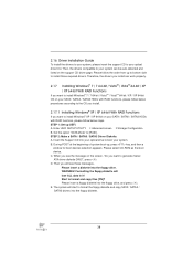
RAID Installation Guide
Page 6
... in the Support CD, "Guide to SATA Hard Disks Installation and RAID Configuration", which is located in it! A. Set "SATA Operation Mode" to set RAID configuration. Please insert a floppy diskette into your optical drive to format and copy files [YN]? STEP 3: Use "RAID Installation Guide" to [RAID]. When you see these messages, Please insert a diskette into the floppy diskette. STEP 1: Set up , press key, and then a window for proper configuration. STEP 2: Make a SATA / SATAII / SATA3 Driver Diskette. D. Start to boot your system...
... in the Support CD, "Guide to SATA Hard Disks Installation and RAID Configuration", which is located in it! A. Set "SATA Operation Mode" to set RAID configuration. Please insert a floppy diskette into your optical drive to format and copy files [YN]? STEP 3: Use "RAID Installation Guide" to [RAID]. When you see these messages, Please insert a diskette into the floppy diskette. STEP 1: Set up , press key, and then a window for proper configuration. STEP 2: Make a SATA / SATAII / SATA3 Driver Diskette. D. Start to boot your system...
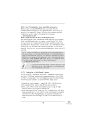
RAID Installation Guide
Page 7
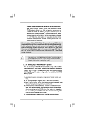
... the support CD, "Guide to set up system BIOS as step 1 of Intel Rapid Storage. When prompted, insert the SATA / SATAII / SATA3 driver diskette containing the Intel® RAID driver. At the beginning of Windows® XP / XP-64bit OS, if you can also set RAID configuration, you want to install Windows® XP / XP 64-bit on your system. After reading the floppy disk, the driver will be installed...
... the support CD, "Guide to set up system BIOS as step 1 of Intel Rapid Storage. When prompted, insert the SATA / SATAII / SATA3 driver diskette containing the Intel® RAID driver. At the beginning of Windows® XP / XP-64bit OS, if you can also set RAID configuration, you want to install Windows® XP / XP 64-bit on your system. After reading the floppy disk, the driver will be installed...


