
User Manual
Page 2
... written consent of merchantability or fitness for any interference received, including interference that may appear in this motherboard contains Perchlorate, a toxic substance controlled in this documentation are used only for identification or explanation and to the implied ...intent to the following two conditions: (1) this device may cause undesired operation. Version 1.0 Published November 2016 Copyright©2016 ASRock INC. Disclaimer: Specifications and information contained in advance. With respect to change without notice, and should not be registered trademarks...
... written consent of merchantability or fitness for any interference received, including interference that may appear in this motherboard contains Perchlorate, a toxic substance controlled in this documentation are used only for identification or explanation and to the implied ...intent to the following two conditions: (1) this device may cause undesired operation. Version 1.0 Published November 2016 Copyright©2016 ASRock INC. Disclaimer: Specifications and information contained in advance. With respect to change without notice, and should not be registered trademarks...
User Manual
Page 6
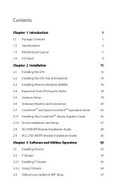
Contents Chapter 1 Introduction 1 1.1 Package Contents 1 1.2 Specifications 2 1.3 Motherboard Layout 7 1.4 I/O Panel 9 Chapter 2 Installation 11 2.1 Installing the CPU 12 2.2 Installing the CPU Fan and Heatsink 15 2.3 Installing Memory Modules (DIMM) 16 2.4 Expansion Slots (PCI Express ... Guide 28 2.9 M.2_SSD (NGFF) Module Installation Guide 30 Chapter 3 Software and Utilities Operation 33 3.1 Installing Drivers 33 3.2 F-Stream 34 3.2.1 Installing F-Stream 34 3.2.2 Using F-Stream 34 3.3 ASRock Live Update & APP Shop 37
Contents Chapter 1 Introduction 1 1.1 Package Contents 1 1.2 Specifications 2 1.3 Motherboard Layout 7 1.4 I/O Panel 9 Chapter 2 Installation 11 2.1 Installing the CPU 12 2.2 Installing the CPU Fan and Heatsink 15 2.3 Installing Memory Modules (DIMM) 16 2.4 Expansion Slots (PCI Express ... Guide 28 2.9 M.2_SSD (NGFF) Module Installation Guide 30 Chapter 3 Software and Utilities Operation 33 3.1 Installing Drivers 33 3.2 F-Stream 34 3.2.1 Installing F-Stream 34 3.2.2 Using F-Stream 34 3.3 ASRock Live Update & APP Shop 37

User Manual
Page 9
ASRock website http://www.asrock.com. 1.1 Package Contents • ASRock Fatal1ty H270 Performance Series Motherboard (ATX Form Factor) • ASRock Fatal1ty H270 Performance Series Quick Installation Guide • ASRock Fatal1ty H270 Performance Series Support CD • 1 x I/O Panel Shield • 2 x Serial ATA (SATA) Data Cables (Optional) • 3 x Screws for purchasing ASRock Fatal1ty H270 Performance Series motherboard, a reliable motherboard produced under ASRock's consistently stringent quality control. In this documentation occur, the updated version will be...
ASRock website http://www.asrock.com. 1.1 Package Contents • ASRock Fatal1ty H270 Performance Series Motherboard (ATX Form Factor) • ASRock Fatal1ty H270 Performance Series Quick Installation Guide • ASRock Fatal1ty H270 Performance Series Support CD • 1 x I/O Panel Shield • 2 x Serial ATA (SATA) Data Cables (Optional) • 3 x Screws for purchasing ASRock Fatal1ty H270 Performance Series motherboard, a reliable motherboard produced under ASRock's consistently stringent quality control. In this documentation occur, the updated version will be...
User Manual
Page 15
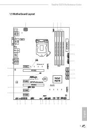
1.3 Motherboard Layout Fatal1ty H270 Performance Series 1 2 34 PS2 Keyboard /Mouse USB 2.0 T: USB1 B: USB2 ATX12V1 CT1 CPU_FAN1 M2_3 ATXPWR1 DDR4_A1 (64 bit, 288-pin module) DDR4_A2 (64 bit, 288-pin module) ...: FRONT Bottom: MIC IN 26 LAN PCIE1 CT4 PCI Express 3.0 CT3 CT2 CT1 PCIE2 CLRMOS1 1 M2_2 RoHS 25 1 FATAL TY CMOS Battery AUDIO CODEC PCIE3 H270 Performance Intel H270 PCIE4 Ultra M.2 PCIe Gen3 x4 T B2 T B1 24 1 1 SATA_0_1 SATA_2_3 SATA_4_5 1 8 9 10 M2_1 23 PCIE5 PCIE6 HD_AUDIO1 1 CI1 1 1 TPMS1 COM1 1 CT4 CT3 CT2 CT1...
1.3 Motherboard Layout Fatal1ty H270 Performance Series 1 2 34 PS2 Keyboard /Mouse USB 2.0 T: USB1 B: USB2 ATX12V1 CT1 CPU_FAN1 M2_3 ATXPWR1 DDR4_A1 (64 bit, 288-pin module) DDR4_A2 (64 bit, 288-pin module) ...: FRONT Bottom: MIC IN 26 LAN PCIE1 CT4 PCI Express 3.0 CT3 CT2 CT1 PCIE2 CLRMOS1 1 M2_2 RoHS 25 1 FATAL TY CMOS Battery AUDIO CODEC PCIE3 H270 Performance Intel H270 PCIE4 Ultra M.2 PCIe Gen3 x4 T B2 T B1 24 1 1 SATA_0_1 SATA_2_3 SATA_4_5 1 8 9 10 M2_1 23 PCIE5 PCIE6 HD_AUDIO1 1 CI1 1 1 TPMS1 COM1 1 CT4 CT3 CT2 CT1...

User Manual
Page 19
Fatal1ty H270 Performance Series Chapter 2 Installation This is an ATX form factor motherboard. Pre-installation Precautions Take note of your motherboard directly on a grounded anti-static pad or in the bag that the motherboard fits into it. Doing so may cause physical injuries and damages to motherboard components. • In order to avoid damage from static electricity to...
Fatal1ty H270 Performance Series Chapter 2 Installation This is an ATX form factor motherboard. Pre-installation Precautions Take note of your motherboard directly on a grounded anti-static pad or in the bag that the motherboard fits into it. Doing so may cause physical injuries and damages to motherboard components. • In order to avoid damage from static electricity to...

User Manual
Page 22
The cover must be placed if you wish to return the motherboard for after service. 14 English Please save and replace the cover if the processor is removed.
The cover must be placed if you wish to return the motherboard for after service. 14 English Please save and replace the cover if the processor is removed.

User Manual
Page 24
...Populated DDR4_A2 Populated Populated DDR4_B1 Populated Populated DDR4_B2 Populated Populated The DIMM only fits in one or three memory module installed. 3. otherwise, this motherboard and DIMM may be damaged. English 16 It is not allowed to install identical (the same brand, speed, size and chip-type)...DDR4 DIMM pairs. 2. For dual channel configuration, you force the DIMM into a DDR4 slot; It will cause permanent damage to the motherboard and the DIMM if you always need to install a DDR, DDR2 or DDR3 memory module into the slot at incorrect orientation. 2.3 Installing...
...Populated DDR4_A2 Populated Populated DDR4_B1 Populated Populated DDR4_B2 Populated Populated The DIMM only fits in one or three memory module installed. 3. otherwise, this motherboard and DIMM may be damaged. English 16 It is not allowed to install identical (the same brand, speed, size and chip-type)...DDR4 DIMM pairs. 2. For dual channel configuration, you force the DIMM into a DDR4 slot; It will cause permanent damage to the motherboard and the DIMM if you always need to install a DDR, DDR2 or DDR3 memory module into the slot at incorrect orientation. 2.3 Installing...
User Manual
Page 26
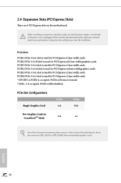
2.4 Expansion Slots (PCI Express Slots) There are 6 PCI Express slots on the motherboard. PCIE6 (PCIe 3.0 x1 slot) is used for PCI Express x1 lane width cards. * If PCIE5 or PCIE6 is occupied, PCIE4 will be disabled. Please read ... Configurations Single Graphics Card PCIE2 x16 PCIE4 N/A Two Graphics Cards in CrossFireXTM Mode x16 x4 For a better thermal environment, please connect a chassis fan to the motherboard's chassis fan connector (CHA_FAN1 or CHA_FAN2) when using multiple graphics cards. English 18 PCIe slots: PCIE1 (PCIe 3.0 x1 slot) is used for PCI Express x1...
2.4 Expansion Slots (PCI Express Slots) There are 6 PCI Express slots on the motherboard. PCIE6 (PCIe 3.0 x1 slot) is used for PCI Express x1 lane width cards. * If PCIE5 or PCIE6 is occupied, PCIE4 will be disabled. Please read ... Configurations Single Graphics Card PCIE2 x16 PCIE4 N/A Two Graphics Cards in CrossFireXTM Mode x16 x4 For a better thermal environment, please connect a chassis fan to the motherboard's chassis fan connector (CHA_FAN1 or CHA_FAN2) when using multiple graphics cards. English 18 PCIe slots: PCIE1 (PCIe 3.0 x1 slot) is used for PCI Express x1...

User Manual
Page 28
Note the positive and negative pins before connecting the cables. PLED (System Power LED): Connect to perform a normal restart. The LED is on when the system is reading or writing data. The LED is on the chassis front panel. English 20 ... The front panel design may configure the way to turn off (S5). RESET (Reset Switch): Connect to the power switch on the chassis to the motherboard. 2.6 Onboard Headers and Connectors Onboard headers and connectors are matched correctly. Do NOT place jumper caps over the headers and connectors will cause permanent damage...
Note the positive and negative pins before connecting the cables. PLED (System Power LED): Connect to perform a normal restart. The LED is on when the system is reading or writing data. The LED is on the chassis front panel. English 20 ... The front panel design may configure the way to turn off (S5). RESET (Reset Switch): Connect to the power switch on the chassis to the motherboard. 2.6 Onboard Headers and Connectors Onboard headers and connectors are matched correctly. Do NOT place jumper caps over the headers and connectors will cause permanent damage...
User Manual
Page 29
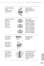
...PLED- SATA_5 SATA_3 These six SATA3 connectors support SATA data cables for internal storage devices with up to this motherboard. Vbus IntA_PA_SSRXIntA_PA_SSRX+ GND IntA_PA_SSTXIntA_PA_SSTX+ GND IntA_PA_DIntA_PA_D+ Vbus IntA_PB_SSRXIntA_PB_SSRX+ GND IntA_PB_SSTXIntA_PB_SSTX+ GND IntA_PB_DIntA_PB_D+ Dummy 1 Besides ...-type M.2 device, SATA_5 will be disabled. * If M2_2 is occupied by a SATA-type M.2 device, SATA_0 will be disabled. Fatal1ty H270 Performance Series Power LED and Speaker Header (7-pin SPK_PLED1) (see p.7, No. 12) Serial ATA3 Connectors (SATA_4_5: see p.7, No. 8) (SATA_2_3...
...PLED- SATA_5 SATA_3 These six SATA3 connectors support SATA data cables for internal storage devices with up to this motherboard. Vbus IntA_PA_SSRXIntA_PA_SSRX+ GND IntA_PA_SSTXIntA_PA_SSTX+ GND IntA_PA_DIntA_PA_D+ Vbus IntA_PB_SSRXIntA_PB_SSRX+ GND IntA_PB_SSTXIntA_PB_SSTX+ GND IntA_PB_DIntA_PB_D+ Dummy 1 Besides ...-type M.2 device, SATA_5 will be disabled. * If M2_2 is occupied by a SATA-type M.2 device, SATA_0 will be disabled. Fatal1ty H270 Performance Series Power LED and Speaker Header (7-pin SPK_PLED1) (see p.7, No. 12) Serial ATA3 Connectors (SATA_4_5: see p.7, No. 8) (SATA_2_3...

User Manual
Page 30
... Control panel and adjust "Recording Volume". Chassis Fan Connectors (4-pin CHA_FAN1) (see p.7, No. 14) (4-pin CHA_FAN2) (see p.7, No. 13) 4 3 21 FAN_SPEED_CONTROL CHA_FAN_SPEED FAN_VOLTAGE GND This motherboard provides two 4-Pin water cooling chassis fan connectors. English Chassis Optional/Water Pump Fan Connector (4-pin CHA_FAN3/W_ PUMP) (see p.7, No. 26) 4 3 21 FAN_SPEED_CONTROL CHA_FAN_SPEED...
... Control panel and adjust "Recording Volume". Chassis Fan Connectors (4-pin CHA_FAN1) (see p.7, No. 14) (4-pin CHA_FAN2) (see p.7, No. 13) 4 3 21 FAN_SPEED_CONTROL CHA_FAN_SPEED FAN_VOLTAGE GND This motherboard provides two 4-Pin water cooling chassis fan connectors. English Chassis Optional/Water Pump Fan Connector (4-pin CHA_FAN3/W_ PUMP) (see p.7, No. 26) 4 3 21 FAN_SPEED_CONTROL CHA_FAN_SPEED...
User Manual
Page 31
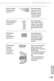
... connector. vides an 8-pin ATX 12V power connector. English 23 ATX Power Connector (24-pin ATXPWR1) (see p.7, No. 1) 8 5 This motherboard pro- To use a 4 1 4-pin ATX power supply, please plug it along Pin 1 and Pin 5. To use a 20-pin ATX ...(5-pin TB1) (see p.7, No. 23) (10-pin TB2) (see p.7, No. 2) FAN_SPEED_CONTROL FAN_SPEED FAN_VOLTAGE GND 4 This motherboard pro- 3 2 vides a 4-Pin CPU fan 1 (Quiet Fan) connector. Fatal1ty H270 Performance Series CPU Fan Connector (4-pin CPU_FAN1) (see p.7, No. 24) DUMMY I2C_DATA I2C_CLOCK IRQ GND 1 GND SLP_S4# SLP_S3# PLUG_EVENT...
... connector. vides an 8-pin ATX 12V power connector. English 23 ATX Power Connector (24-pin ATXPWR1) (see p.7, No. 1) 8 5 This motherboard pro- To use a 4 1 4-pin ATX power supply, please plug it along Pin 1 and Pin 5. To use a 20-pin ATX ...(5-pin TB1) (see p.7, No. 23) (10-pin TB2) (see p.7, No. 2) FAN_SPEED_CONTROL FAN_SPEED FAN_VOLTAGE GND 4 This motherboard pro- 3 2 vides a 4-Pin CPU fan 1 (Quiet Fan) connector. Fatal1ty H270 Performance Series CPU Fan Connector (4-pin CPU_FAN1) (see p.7, No. 24) DUMMY I2C_DATA I2C_CLOCK IRQ GND 1 GND SLP_S4# SLP_S3# PLUG_EVENT...

User Manual
Page 32
... (17-pin TPMS1) (see p.7, No. 20) 1 AURA RGB LED Header (4-pin RGB_LED) (see p.7, No. 19) RRXD1 DDTR#1 DDSR#1 CCTS#1 1 RRI#1 RRTS#1 GND TTXD1 DDCD#1 This motherboard supports CASE OPEN detection feature that detects if the chassis cover has been removed. A TPM system also helps enhance network security, protects digital identities, and...
... (17-pin TPMS1) (see p.7, No. 20) 1 AURA RGB LED Header (4-pin RGB_LED) (see p.7, No. 19) RRXD1 DDTR#1 DDSR#1 CCTS#1 1 RRI#1 RRTS#1 GND TTXD1 DDCD#1 This motherboard supports CASE OPEN detection feature that detects if the chassis cover has been removed. A TPM system also helps enhance network security, protects digital identities, and...

User Manual
Page 33
... cards are AMD certified. 2. Download the drivers from the AMD's website: www.amd.com 3. Fatal1ty H270 Performance Series 2.7 CrossFireXTM and Quad CrossFireXTM Operation Guide This motherboard supports CrossFireXTM and Quad CrossFireXTM that allows you purchase, not bundled with this motherboard. Make sure that your system requires. CrossFire Bridge Step 2 Connect two graphics cards by installing...
... cards are AMD certified. 2. Download the drivers from the AMD's website: www.amd.com 3. Fatal1ty H270 Performance Series 2.7 CrossFireXTM and Quad CrossFireXTM Operation Guide This motherboard supports CrossFireXTM and Quad CrossFireXTM that allows you purchase, not bundled with this motherboard. Make sure that your system requires. CrossFire Bridge Step 2 Connect two graphics cards by installing...

User Manual
Page 39
... the standoff into the M.2 slot. Step 5 Align and gently insert the M.2 (NGFF) SSD module into the desired nut location on the motherboard. Step 6 Tighten the screw with a screwdriver to be aware that the M.2 (NGFF) SSD module only fits in one orientation. Please be... default. Step 4 Peel off the yellow protective film on the module type and length. 4 3 2 1 D C B A D C B A D C B A C B A D NUT2 NUT1 Fatal1ty H270 Performance Series Step 3 Move the standoff based on the nut to secure the module into place. Skip Step 3 and 4 and go straight to Step 5 if you...
... the standoff into the M.2 slot. Step 5 Align and gently insert the M.2 (NGFF) SSD module into the desired nut location on the motherboard. Step 6 Tighten the screw with a screwdriver to be aware that the M.2 (NGFF) SSD module only fits in one orientation. Please be... default. Step 4 Peel off the yellow protective film on the module type and length. 4 3 2 1 D C B A D C B A D C B A C B A D NUT2 NUT1 Fatal1ty H270 Performance Series Step 3 Move the standoff based on the nut to secure the module into place. Skip Step 3 and 4 and go straight to Step 5 if you...

User Manual
Page 41
... order from top to bottom to display the menu. Utilities Menu The Utilities Menu shows the application software that enhance the motherboard's features. Running The Support CD To begin using the support CD, insert the CD into your system will be auto... drive. Drivers Menu The drivers compatible to install it. Fatal1ty H270 Performance Series Chapter 3 Software and Utilities Operation 3.1 Installing Drivers The Support CD that comes with the motherboard contains necessary drivers and useful utilities that the motherboard supports. The CD automatically displays the Main Menu if "AUTORUN...
... order from top to bottom to display the menu. Utilities Menu The Utilities Menu shows the application software that enhance the motherboard's features. Running The Support CD To begin using the support CD, insert the CD into your system will be auto... drive. Drivers Menu The drivers compatible to install it. Fatal1ty H270 Performance Series Chapter 3 Software and Utilities Operation 3.1 Installing Drivers The Support CD that comes with the motherboard contains necessary drivers and useful utilities that the motherboard supports. The CD automatically displays the Main Menu if "AUTORUN...
User Manual
Page 45
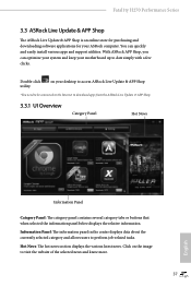
... the website of the selected news and know more. 37 English Double-click utility. Fatal1ty H270 Performance Series 3.3 ASRock Live Update & APP Shop The ASRock Live Update & APP Shop is an online store for purchasing and downloading software applications for your motherboard up to date simply with a few clicks. You can optimize your system and keep...
... the website of the selected news and know more. 37 English Double-click utility. Fatal1ty H270 Performance Series 3.3 ASRock Live Update & APP Shop The ASRock Live Update & APP Shop is an online store for purchasing and downloading software applications for your motherboard up to date simply with a few clicks. You can optimize your system and keep...

User Manual
Page 52
...® 7 Installation Intel® new processors have an ODD and PS/2 ports: If there is not included in the ASRock Support CD or downloaded from website) Scenarios You have removed removed their motherboard won't work. Due to that fact that XHCI is an optical disc drive, PS/2 ports and PS/2 Keyboard or...
...® 7 Installation Intel® new processors have an ODD and PS/2 ports: If there is not included in the ASRock Support CD or downloaded from website) Scenarios You have removed removed their motherboard won't work. Due to that fact that XHCI is an optical disc drive, PS/2 ports and PS/2 Keyboard or...
User Manual
Page 62
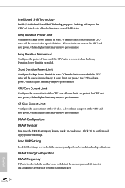
... the CPU ratio is lowered when the Long Duration Power Limit is selected, the motherboard will be lowered after a period of the CPU core. Click OK to overclock the memory and perform beyond standard specifications DRAM Timing Configuration DRAM Frequency If [Auto] is exceeded. When ... to allow for hardware controlled P-states. A lower limit can protect the CPU and save power, while a higher limit may improve performance. DRAM Configuration DRAM Tweaker Fine tune the DRAM settings by leaving marks in watts. Intel Speed Shift Technology Enable/Disable Intel Speed Shift...
... the CPU ratio is lowered when the Long Duration Power Limit is selected, the motherboard will be lowered after a period of the CPU core. Click OK to overclock the memory and perform beyond standard specifications DRAM Timing Configuration DRAM Frequency If [Auto] is exceeded. When ... to allow for hardware controlled P-states. A lower limit can protect the CPU and save power, while a higher limit may improve performance. DRAM Configuration DRAM Tweaker Fine tune the DRAM settings by leaving marks in watts. Intel Speed Shift Technology Enable/Disable Intel Speed Shift...

User Manual
Page 83
Fan-Tastic Tuning Select a fan mode for CPU Fans 1&2, or choose Customize to set 5 CPU temperatures and assign a respective fan speed for each temperature. Fatal1ty H270 Performance Series 4.8 Hardware Health Event Monitoring Screen This section allows you to set 5 CPU temperatures and assign a respective fan speed for each temperature. CPU Fan Step ... a fan mode for CPU Fans 1, or choose Customize to monitor the status of the hardware on your system, including the parameters of the CPU temperature, motherboard temperature, fan speed and voltage.
Fan-Tastic Tuning Select a fan mode for CPU Fans 1&2, or choose Customize to set 5 CPU temperatures and assign a respective fan speed for each temperature. Fatal1ty H270 Performance Series 4.8 Hardware Health Event Monitoring Screen This section allows you to set 5 CPU temperatures and assign a respective fan speed for each temperature. CPU Fan Step ... a fan mode for CPU Fans 1, or choose Customize to monitor the status of the hardware on your system, including the parameters of the CPU temperature, motherboard temperature, fan speed and voltage.


