User Manual
Page 3
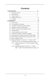
... 9 1.4 Motherboard Layout 12 1.5 I/O Panel 13 2 Installation 14 2.1 Screw Holes 14 2.2 Pre-installation Precautions 14 2.3 Installation of Memory Modules (DIMM 15 2.4 Expansion Slot (PCI Express Slot 16 2.5 ASRock Smart Remote Installation Guide 17 2.6 Jumpers Setup 19 2.7 Onboard Headers and Connectors 20 2.8 Serial ATA3 (SATA3) Hard Disks Installation 24 2.9 Hot Plug and Hot Swap Functions for SATA3 HDDs .... 24 2.10 SATA3 HDD Hot Plug Feature and Operation Guide ... . 25 2.11 Driver Installation Guide 27 2.12 Installing Windows® 8 / 8 64-bit / 7 / 7 64-bit / VistaTM...
... 9 1.4 Motherboard Layout 12 1.5 I/O Panel 13 2 Installation 14 2.1 Screw Holes 14 2.2 Pre-installation Precautions 14 2.3 Installation of Memory Modules (DIMM 15 2.4 Expansion Slot (PCI Express Slot 16 2.5 ASRock Smart Remote Installation Guide 17 2.6 Jumpers Setup 19 2.7 Onboard Headers and Connectors 20 2.8 Serial ATA3 (SATA3) Hard Disks Installation 24 2.9 Hot Plug and Hot Swap Functions for SATA3 HDDs .... 24 2.10 SATA3 HDD Hot Plug Feature and Operation Guide ... . 25 2.11 Driver Installation Guide 27 2.12 Installing Windows® 8 / 8 64-bit / 7 / 7 64-bit / VistaTM...
User Manual
Page 5
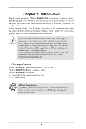
...are using. Chapter 1: Introduction Thank you for specific information about the model you require technical support related to change without further notice. Because the motherboard specifications and the BIOS software might be updated, the content of the Support CD. www.asrock.com/support/index.asp 1.1 Package Contents ASRock E35LM1 R2.0 Motherboard (Mini-ITX Form Factor) ASRock E35LM1 R2.0 Quick Installation Guide ASRock E35LM1 R2.0 Support CD 2 x Serial ATA (SATA) Data Cables (Optional) 1 x I/O Panel Shield ASRock Reminds You... Chapter 3 and 4 contain the configuration guide to...
...are using. Chapter 1: Introduction Thank you for specific information about the model you require technical support related to change without further notice. Because the motherboard specifications and the BIOS software might be updated, the content of the Support CD. www.asrock.com/support/index.asp 1.1 Package Contents ASRock E35LM1 R2.0 Motherboard (Mini-ITX Form Factor) ASRock E35LM1 R2.0 Quick Installation Guide ASRock E35LM1 R2.0 Support CD 2 x Serial ATA (SATA) Data Cables (Optional) 1 x I/O Panel Shield ASRock Reminds You... Chapter 3 and 4 contain the configuration guide to...
User Manual
Page 7
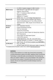
...CPU Quiet Fan (Allow Chassis Fan Speed Auto-Adjust by overclocking. 7 Overclocking may affect your system's stability, or even cause damage to the components and devices of your own risk and expense. Supports "Plug and Play" - Drivers, Utilities, AntiVirus Software (Trial Version), CyberLink MediaEspresso 6.5 Trial, ASRock MAGIX Multimedia Suite - ACPI 1.1 Compliance Wake Up Events - - 2 x USB 2.0 headers (support 4 USB 2.0 ports) BIOS Feature - 32Mb AMI UEFI Legal BIOS with overclocking, including adjusting the setting in the BIOS, applying Untied Overclocking Technology, or using...
...CPU Quiet Fan (Allow Chassis Fan Speed Auto-Adjust by overclocking. 7 Overclocking may affect your system's stability, or even cause damage to the components and devices of your own risk and expense. Supports "Plug and Play" - Drivers, Utilities, AntiVirus Software (Trial Version), CyberLink MediaEspresso 6.5 Trial, ASRock MAGIX Multimedia Suite - ACPI 1.1 Compliance Wake Up Events - - 2 x USB 2.0 headers (support 4 USB 2.0 ports) BIOS Feature - 32Mb AMI UEFI Legal BIOS with overclocking, including adjusting the setting in the BIOS, applying Untied Overclocking Technology, or using...
User Manual
Page 9
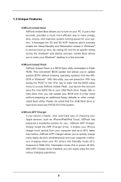
... ACPI features which normally enable the Sleep/Standby and Hibernation modes in Flash ROM. By calling S3 and S4 at specific timing during the POST or the key to enter into Standby mode (S1), Suspend to your USB flash drive, floppy disk or hard drive, then you can update your computer and up time. Please be noted that the USB flash drive or hard drive must use FAT32/16/12 file system. Simply install the APP Charger driver...
... ACPI features which normally enable the Sleep/Standby and Hibernation modes in Flash ROM. By calling S3 and S4 at specific timing during the POST or the key to enter into Standby mode (S1), Suspend to your USB flash drive, floppy disk or hard drive, then you can update your computer and up time. Please be noted that the USB flash drive or hard drive must use FAT32/16/12 file system. Simply install the APP Charger driver...
User Manual
Page 12
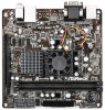
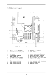
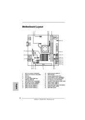
... 3 CPU Fan 4 CPU Heatsink 5 2 x 240-pin DDR3 DIMM Slots (DDR3_A1, DDR3_A2) 6 Clear CMOS Jumper (CLRCMOS1) 7 ATX Power Connector (ATXPWR1) 8 System Panel Header (PANEL1) 9 SATA3 Connector (SATA3_4) 10 SATA3 Connector (SATA3_2) 11 SATA3 Connector (SATA3_3) 12 SATA3 Connector (SATA3_1) 13 32Mb SPI Flash 14 Chassis Intrusion Header (CI1) 15 Chassis Speaker Header (SPEAKER1) 16 Chassis Fan Connector (CHA_FAN2) 17 PCI Express 2.0 x16 Slot (PCIE1) 18 Consumer Infrared Module Header (CIR1) 19 USB 2.0 Header (USB8_9) 20 USB 2.0 Header (USB6_7) 21 Front Panel Audio Header (HD_AUDIO1) 22 COM Port Header...
... 3 CPU Fan 4 CPU Heatsink 5 2 x 240-pin DDR3 DIMM Slots (DDR3_A1, DDR3_A2) 6 Clear CMOS Jumper (CLRCMOS1) 7 ATX Power Connector (ATXPWR1) 8 System Panel Header (PANEL1) 9 SATA3 Connector (SATA3_4) 10 SATA3 Connector (SATA3_2) 11 SATA3 Connector (SATA3_3) 12 SATA3 Connector (SATA3_1) 13 32Mb SPI Flash 14 Chassis Intrusion Header (CI1) 15 Chassis Speaker Header (SPEAKER1) 16 Chassis Fan Connector (CHA_FAN2) 17 PCI Express 2.0 x16 Slot (PCIE1) 18 Consumer Infrared Module Header (CIR1) 19 USB 2.0 Header (USB8_9) 20 USB 2.0 Header (USB6_7) 21 Front Panel Audio Header (HD_AUDIO1) 22 COM Port Header...
User Manual
Page 25
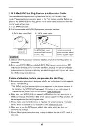
... reduce the risk of our motherboard is indicated in RAID / AHCI mode. Please read below operation guide of attention, before you process the SATA3 HDD Hot Plug, please check below instructions step by the chipset because of its limitation, the SATA3 Hot Plug support information of HDD crash or data loss. 25 Without SATA 15-pin power connector interface, the SATA3 Hot Plug cannot be damaged under...
... reduce the risk of our motherboard is indicated in RAID / AHCI mode. Please read below operation guide of attention, before you process the SATA3 HDD Hot Plug, please check below instructions step by the chipset because of its limitation, the SATA3 Hot Plug support information of HDD crash or data loss. 25 Without SATA 15-pin power connector interface, the SATA3 Hot Plug cannot be damaged under...
User Manual
Page 27
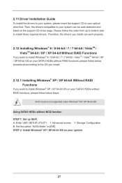
B. Enter UEFI SETUP UTILITY Advanced screen Storage Configuration. Set the option "SATA Mode" to [IDE]. Therefore, the drivers you want to install Windows® 8 / 8 64-bit / 7 / 7 64-bit / VistaTM / VistaTM 64-bit / XP / XP 64-bit OS on your SATA3 HDDs without RAID functions, please follow below steps. STEP 2: Install Windows® XP / XP 64-bit OS on your SATA3 HDDs without NCQ function STEP 1: Set up to bottom side to install those required drivers. Please follow the order...
B. Enter UEFI SETUP UTILITY Advanced screen Storage Configuration. Set the option "SATA Mode" to [IDE]. Therefore, the drivers you want to install Windows® 8 / 8 64-bit / 7 / 7 64-bit / VistaTM / VistaTM 64-bit / XP / XP 64-bit OS on your SATA3 HDDs without RAID functions, please follow below steps. STEP 2: Install Windows® XP / XP 64-bit OS on your SATA3 HDDs without NCQ function STEP 1: Set up to bottom side to install those required drivers. Please follow the order...
User Manual
Page 38
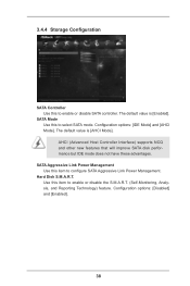
... will improve SATA disk performance but IDE mode does not have these advantages. Hard Disk S.M.A.R.T. 3.4.4 Storage Configuration SATA Controller Use this item to enable or disable the S.M.A.R.T. (Self-Monitoring, Analysis, and Reporting Technology) feature. The default value is [AHCI Mode]. Configuration options: [IDE Mode] and [AHCI Mode]. Use this to enable or disable SATA controller. SATA Mode Use this item to select SATA mode. SATA Aggressive Link Power Management Use this to configure SATA Aggressive Link Power Management. Configuration options: [Disabled] and [Enabled]. 38...
... will improve SATA disk performance but IDE mode does not have these advantages. Hard Disk S.M.A.R.T. 3.4.4 Storage Configuration SATA Controller Use this item to enable or disable the S.M.A.R.T. (Self-Monitoring, Analysis, and Reporting Technology) feature. The default value is [AHCI Mode]. Configuration options: [IDE Mode] and [AHCI Mode]. Use this to enable or disable SATA controller. SATA Mode Use this item to select SATA mode. SATA Aggressive Link Power Management Use this to configure SATA Aggressive Link Power Management. Configuration options: [Disabled] and [Enabled]. 38...
User Manual
Page 40
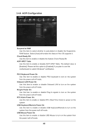
... to enable or disable Onboard LAN to turn on the system. USB Keyboard/Remote Power On Use this item to enable or disable USB Keyboard/Remote to enable or disable ACPI HPET Table. Check Ready Bit Use this item to power on the system from the power-soft-off mode. RTC Alarm Power On Use this item to enable or disable RTC (Real Time Clock) to enable or disable the feature Check Ready Bit. The default value is [Enabled]. 3.4.6 ACPI Configuration Suspend to RAM Use...
... to enable or disable Onboard LAN to turn on the system. USB Keyboard/Remote Power On Use this item to enable or disable USB Keyboard/Remote to enable or disable ACPI HPET Table. Check Ready Bit Use this item to power on the system from the power-soft-off mode. RTC Alarm Power On Use this item to enable or disable RTC (Real Time Clock) to enable or disable the feature Check Ready Bit. The default value is [Enabled]. 3.4.6 ACPI Configuration Suspend to RAM Use...

User Manual
Page 42
... UEFI setup when [Disabled] is selected. The default value is recommended to select [Disabled] to below descriptions for legacy USB. [Auto] - Legacy USB Support Use this item to select legacy support for USB devices. Enables legacy support if USB devices are four configuration options: [Enabled], [Auto], [Disabled] and [UEFI Setup Only]. 3.4.7 USB Configuration USB 2.0 Controller Use this option to enable or disable the use of these four options: [Enabled] - Please refer to enter OS. [UEFI Setup Only] - There are connected. [Disabled] - If you have USB compatibility issue...
... UEFI setup when [Disabled] is selected. The default value is recommended to select [Disabled] to below descriptions for legacy USB. [Auto] - Legacy USB Support Use this item to select legacy support for USB devices. Enables legacy support if USB devices are four configuration options: [Enabled], [Auto], [Disabled] and [UEFI Setup Only]. 3.4.7 USB Configuration USB 2.0 Controller Use this option to enable or disable the use of these four options: [Enabled] - Please refer to enter OS. [UEFI Setup Only] - There are connected. [Disabled] - If you have USB compatibility issue...

User Manual
Page 45
... [Full On]. Configuration options: [Full On] and [Manual Mode]. The default is value [Full On]. Configuration options: [Full On] and [Automatic Mode]. Case Open Feature This allows you to set the CPU fan speed. CPU Fan Setting This allows you to enable or disable case open has been detected. The default is value [Full On]. 3.6 Hardware Health Event Monitoring Screen In this option to keep or clear the record of the CPU temperature, motherboard temperature, CPU fan speed, chassis fan speed, and the critical voltage.
... [Full On]. Configuration options: [Full On] and [Manual Mode]. The default is value [Full On]. Configuration options: [Full On] and [Automatic Mode]. Case Open Feature This allows you to set the CPU fan speed. CPU Fan Setting This allows you to enable or disable case open has been detected. The default is value [Full On]. 3.6 Hardware Health Event Monitoring Screen In this option to keep or clear the record of the CPU temperature, motherboard temperature, CPU fan speed, chassis fan speed, and the critical voltage.
User Manual
Page 50
... only. or you need to contact ASRock or want to know more information. 4.2 Support CD Information The Support CD that came with the motherboard contains necessary drivers and useful utilities that the motherboard supports. Please install the necessary drivers to display the menus. 4.2.2 Drivers Menu The Drivers Menu shows the available devices drivers if the system detects installed devices. Because motherboard settings and hardware options vary, use the setup procedures in your dealer for further...
... only. or you need to contact ASRock or want to know more information. 4.2 Support CD Information The Support CD that came with the motherboard contains necessary drivers and useful utilities that the motherboard supports. Please install the necessary drivers to display the menus. 4.2.2 Drivers Menu The Drivers Menu shows the available devices drivers if the system detects installed devices. Because motherboard settings and hardware options vary, use the setup procedures in your dealer for further...
Quick Installation Guide
Page 2
... 3 CPU Fan 4 CPU Heatsink 5 2 x 240-pin DDR3 DIMM Slots (DDR3_A1, DDR3_A2) 6 Clear CMOS Jumper (CLRCMOS1) 7 ATX Power Connector (ATXPWR1) 8 System Panel Header (PANEL1) 9 SATA3 Connector (SATA3_4) 10 SATA3 Connector (SATA3_2) 11 SATA3 Connector (SATA3_3) 12 SATA3 Connector (SATA3_1) 13 32Mb SPI Flash 14 Chassis Intrusion Header (CI1) 15 Chassis Speaker Header (SPEAKER1) 16 Chassis Fan Connector (CHA_FAN2) 17 PCI Express 2.0 x16 Slot (PCIE1) 18 Consumer Infrared Module Header (CIR1) 19 USB 2.0 Header (USB8_9) 20 USB 2.0 Header (USB6_7) 21 Front Panel Audio Header (HD_AUDIO1) 22 COM Port Header...
... 3 CPU Fan 4 CPU Heatsink 5 2 x 240-pin DDR3 DIMM Slots (DDR3_A1, DDR3_A2) 6 Clear CMOS Jumper (CLRCMOS1) 7 ATX Power Connector (ATXPWR1) 8 System Panel Header (PANEL1) 9 SATA3 Connector (SATA3_4) 10 SATA3 Connector (SATA3_2) 11 SATA3 Connector (SATA3_3) 12 SATA3 Connector (SATA3_1) 13 32Mb SPI Flash 14 Chassis Intrusion Header (CI1) 15 Chassis Speaker Header (SPEAKER1) 16 Chassis Fan Connector (CHA_FAN2) 17 PCI Express 2.0 x16 Slot (PCIE1) 18 Consumer Infrared Module Header (CIR1) 19 USB 2.0 Header (USB8_9) 20 USB 2.0 Header (USB6_7) 21 Front Panel Audio Header (HD_AUDIO1) 22 COM Port Header...
Quick Installation Guide
Page 4
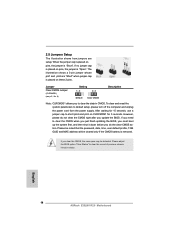
... of the motherboard and step-bystep installation guide. www.asrock.com/support/index.asp 1.1 Package Contents ASRock E35LM1 R2.0 Motherboard (Mini-ITX Form Factor) ASRock E35LM1 R2.0 Quick Installation Guide ASRock E35LM1 R2.0 Support CD 2 x Serial ATA (SATA) Data Cables (Optional) 1 x I/O Panel Shield ASRock Reminds You... To get better performance in Windows® 8 / 8 64-bit / 7 / 7 64-bit / VistaTM / VistaTM 64-bit, it is recommended to set the BIOS option in the Support CD. You may find the latest VGA cards and CPU support lists on ASRock website...
... of the motherboard and step-bystep installation guide. www.asrock.com/support/index.asp 1.1 Package Contents ASRock E35LM1 R2.0 Motherboard (Mini-ITX Form Factor) ASRock E35LM1 R2.0 Quick Installation Guide ASRock E35LM1 R2.0 Support CD 2 x Serial ATA (SATA) Data Cables (Optional) 1 x I/O Panel Shield ASRock Reminds You... To get better performance in Windows® 8 / 8 64-bit / 7 / 7 64-bit / VistaTM / VistaTM 64-bit, it is recommended to set the BIOS option in the Support CD. You may find the latest VGA cards and CPU support lists on ASRock website...

Quick Installation Guide
Page 6
... 6 ASRock E35LM1 R2.0 Motherboard SMBIOS 2.3.1 Support - CPU Temperature Sensing Monitor - Supports jumperfree - Chassis Temperature Sensing - Chassis Fan Tachometer - CASE OPEN detection - FCC, CE, WHQL - Overclocking may affect your system's stability, or even cause damage to the components and devices of your own risk and expense. OEM, Google Chrome Browser and Toolbar Hardware - CPU Fan Tachometer - - 2 x USB 2.0 headers (support 4 USB 2.0 ports) BIOS Feature - 32Mb AMI UEFI Legal BIOS with overclocking, including adjusting the setting in the BIOS...
... 6 ASRock E35LM1 R2.0 Motherboard SMBIOS 2.3.1 Support - CPU Temperature Sensing Monitor - Supports jumperfree - Chassis Temperature Sensing - Chassis Fan Tachometer - CASE OPEN detection - FCC, CE, WHQL - Overclocking may affect your system's stability, or even cause damage to the components and devices of your own risk and expense. OEM, Google Chrome Browser and Toolbar Hardware - CPU Fan Tachometer - - 2 x USB 2.0 headers (support 4 USB 2.0 ports) BIOS Feature - 32Mb AMI UEFI Legal BIOS with overclocking, including adjusting the setting in the BIOS...

Quick Installation Guide
Page 8
... key to enter into Standby mode (S1), Suspend to update system BIOS without preparing an additional floppy diskette or other complicated flash utility. This convenient BIOS update tool allows you can easily enjoy the marvelous charging experience. 8 ASRock E35LM1 R2.0 Motherboard English ASRock APP Charger If you can press the key during the shutdown and startup process, Instant Boot allows you to your USB...
... key to enter into Standby mode (S1), Suspend to update system BIOS without preparing an additional floppy diskette or other complicated flash utility. This convenient BIOS update tool allows you can easily enjoy the marvelous charging experience. 8 ASRock E35LM1 R2.0 Motherboard English ASRock APP Charger If you can press the key during the shutdown and startup process, Instant Boot allows you to your USB...
Quick Installation Guide
Page 14
... the password, date, time, user default profile, 1394 GUID and MAC address will be detected. If no jumper cap is placed on pins, the jumper is "Short". After waiting for 5 seconds. If you to clear the data in CMOS. If you need to default setup, please turn off the computer and unplug the power cord from the power supply. Please adjust the BIOS option "Clear Status" to short pin2...
... the password, date, time, user default profile, 1394 GUID and MAC address will be detected. If no jumper cap is placed on pins, the jumper is "Short". After waiting for 5 seconds. If you to clear the data in CMOS. If you need to default setup, please turn off the computer and unplug the power cord from the power supply. Please adjust the BIOS option "Clear Status" to short pin2...
Quick Installation Guide
Page 17
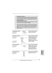
... the system is reading or writing data. Please connect the CPU fan cable to the connector and match the black wire to this header. The LED is on when the hard drive is in S1 sleep state. A front panel module mainly consists of power switch, reset switch, power LED, hard drive activity LED, speaker and etc. Please connect the fan cables to the fan connectors and match the black wire to the ground pin. The front panel design may differ by fan power voltage.
... the system is reading or writing data. Please connect the CPU fan cable to the connector and match the black wire to this header. The LED is on when the hard drive is in S1 sleep state. A front panel module mainly consists of power switch, reset switch, power LED, hard drive activity LED, speaker and etc. Please connect the fan cables to the fan connectors and match the black wire to the ground pin. The front panel design may differ by fan power voltage.
Quick Installation Guide
Page 18
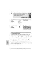
... 20-pin ATX power supply. This feature requires a chassis with Pin 1 and Pin 13. 20-Pin ATX Power Supply Installation 1 13 Serial port Header (9-pin COM1) (see p.2 No. 14) 1 GND Signal This motherboard supports CASE OPEN detection feature that detects if the chassis cover has been removed. English 18 ASRock E35LM1 R2.0 Motherboard Then, the drivers compatible to the OS you install. Though this motherboard provides 24-pin ATX power connector, 12 24 it can be auto-detected and listed on your SATA3 HDDs without RAID functions...
... 20-pin ATX power supply. This feature requires a chassis with Pin 1 and Pin 13. 20-Pin ATX Power Supply Installation 1 13 Serial port Header (9-pin COM1) (see p.2 No. 14) 1 GND Signal This motherboard supports CASE OPEN detection feature that detects if the chassis cover has been removed. English 18 ASRock E35LM1 R2.0 Motherboard Then, the drivers compatible to the OS you install. Though this motherboard provides 24-pin ATX power connector, 12 24 it can be auto-detected and listed on your SATA3 HDDs without RAID functions...
Quick Installation Guide
Page 20
otherwise, POST continues with the motherboard contains necessary drivers and useful utilities that will display the Main Menu automatically if "AUTORUN" is enabled in your CD-ROM drive. To begin using the Support CD, insert the CD into your computer. For the detailed information about BIOS Setup, please refer to enter BIOS Setup utility; When you start up the computer, please press or during the Power-On-Self-Test (POST) to the User Manual (PDF fi...
otherwise, POST continues with the motherboard contains necessary drivers and useful utilities that will display the Main Menu automatically if "AUTORUN" is enabled in your CD-ROM drive. To begin using the Support CD, insert the CD into your computer. For the detailed information about BIOS Setup, please refer to enter BIOS Setup utility; When you start up the computer, please press or during the Power-On-Self-Test (POST) to the User Manual (PDF fi...


