
User Manual
Page 3
..., it . Set up your system. Do not block or cover these openings. Use this product near water or a heated source such as a result of the devices plugged into the system. • The system does not function properly even if you follow all power, modem, and network cables from the power outlets before you operate your system Read and follow the operating instructions. •...
..., it . Set up your system. Do not block or cover these openings. Use this product near water or a heated source such as a result of the devices plugged into the system. • The system does not function properly even if you follow all power, modem, and network cables from the power outlets before you operate your system Read and follow the operating instructions. •...

User Manual
Page 5
... Introduction ...7.1.1 BIOS Menu Bar ...7.1.2 Navigation Keys ...7.2 Main Screen ...7.3 OC Tweaker Screen ...7.4 Advanced Screen ...7.4.1 CPU Configuration ...7.4.2 Chipset Configuration ...7.4.3 ACPI Configuration ...7.4.4 Storage Configuration ...7.4.5 USB Configuration ... 14 18 20 22 23 23 23 24 26 26 26 30 32 33 34 35 36 36 37 37 38 41 42 44 45 46 47 7 BIOS S ETUP UTILITY ...36 SETUP 5 Contents 1 Introduction ...7 1.1 1.2 1.3 1.4 1.5 1.6 Package Contents ...Specifications ...System Motherboard Components ...Rear Panel Connections ...System Chassis ...Remote Controller ...7 8 9 11...
... Introduction ...7.1.1 BIOS Menu Bar ...7.1.2 Navigation Keys ...7.2 Main Screen ...7.3 OC Tweaker Screen ...7.4 Advanced Screen ...7.4.1 CPU Configuration ...7.4.2 Chipset Configuration ...7.4.3 ACPI Configuration ...7.4.4 Storage Configuration ...7.4.5 USB Configuration ... 14 18 20 22 23 23 23 24 26 26 26 30 32 33 34 35 36 36 37 37 38 41 42 44 45 46 47 7 BIOS S ETUP UTILITY ...36 SETUP 5 Contents 1 Introduction ...7 1.1 1.2 1.3 1.4 1.5 1.6 Package Contents ...Specifications ...System Motherboard Components ...Rear Panel Connections ...System Chassis ...Remote Controller ...7 8 9 11...

User Manual
Page 6
7.5 Hardware Health Event Monitoring Screen ...7.6 Boot Screen ...7.6.1 Boot Settings Configuration ...7.7 Security Screen ...7.8 Exit Screen ...8.1 Install Operating System ...8.2 Support CD Information ...8.2.1 Running Support CD ...8.2.2 Drivers Menu ...8.2.3 Utilities Menu ...8.2.4 Contact Information ... 48 48 49 50 51 52 52 52 52 52 52 8 Software Support ...52 6
7.5 Hardware Health Event Monitoring Screen ...7.6 Boot Screen ...7.6.1 Boot Settings Configuration ...7.7 Security Screen ...7.8 Exit Screen ...8.1 Install Operating System ...8.2 Support CD Information ...8.2.1 Running Support CD ...8.2.2 Drivers Menu ...8.2.3 Utilities Menu ...8.2.4 Contact Information ... 48 48 49 50 51 52 52 52 52 52 52 8 Software Support ...52 6

User Manual
Page 7
... are using. www.asrock.com/support/index.asp 1.1 Package Contents ASRock Core 100 Series ASRock Support CD ASRock Quick Start Guide One AC Power Cord One AC/DC Adapter One HDMI to quality and endurance. Because the hardware specifications and the BIOS software might be subject to the hardware installation. It delivers excellent performance with robust design conforming to ASRock's commitment to DVI Adapter One Anti-Slip Pad Remote Controller (Core 100HT / Core 100HT-BD) SATA and Power Cables 7 In this manual will...
... are using. www.asrock.com/support/index.asp 1.1 Package Contents ASRock Core 100 Series ASRock Support CD ASRock Quick Start Guide One AC Power Cord One AC/DC Adapter One HDMI to quality and endurance. Because the hardware specifications and the BIOS software might be subject to the hardware installation. It delivers excellent performance with robust design conforming to ASRock's commitment to DVI Adapter One Anti-Slip Pad Remote Controller (Core 100HT / Core 100HT-BD) SATA and Power Cables 7 In this manual will...

User Manual
Page 8
... AHCI mode only. Processor Chipset Memory VGA HDD DVD Front I/O Rear I/O Sound LAN WiFi Remote Controller Power Dimension Volume (liters) *1 *2 *3 Due to WinXP and PCH chipset (HM55) limitations, if you use WinXP, please disable the BIOS option "USB2.0 Rate Matching Hub" to the components and devices of installing WinXP or using the third-party overclocking tools. Overclocking may not contain memory, HDD or ODD. 1.2 * Specifications Support Intel® Core TM i3/i5/i7 Mobile Processor (Arrandale CPU...
... AHCI mode only. Processor Chipset Memory VGA HDD DVD Front I/O Rear I/O Sound LAN WiFi Remote Controller Power Dimension Volume (liters) *1 *2 *3 Due to WinXP and PCH chipset (HM55) limitations, if you use WinXP, please disable the BIOS option "USB2.0 Rate Matching Hub" to the components and devices of installing WinXP or using the third-party overclocking tools. Overclocking may not contain memory, HDD or ODD. 1.2 * Specifications Support Intel® Core TM i3/i5/i7 Mobile Processor (Arrandale CPU...
User Manual
Page 9
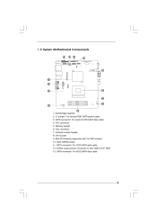
Fan connector 7. CPU socket 9. SATA connector: For HDD SATA data cable EuP Ready RoHS DDR3_A1FSB800 DDR3_B1 9 J1 jumper: For second HDD SATA power cable 3. Infrared module header 8. Fan connector 5. Clear CMOS jumper 11. SATA connector: For ODD SATA data cable 12. SATA connector: For second HDD SATA data cable 4. Memory socket 6. Mini-PCI Express expansion slot: For WiFi module 10. ATX5V output power connector for slim ODD & 2.5" HDD 13. Northbridge heatsink 2. 1.3 System Motherboard Components HM55-HT Design in Taipei PCIE1 1.
Fan connector 7. CPU socket 9. SATA connector: For HDD SATA data cable EuP Ready RoHS DDR3_A1FSB800 DDR3_B1 9 J1 jumper: For second HDD SATA power cable 3. Infrared module header 8. Fan connector 5. Clear CMOS jumper 11. SATA connector: For ODD SATA data cable 12. SATA connector: For second HDD SATA data cable 4. Memory socket 6. Mini-PCI Express expansion slot: For WiFi module 10. ATX5V output power connector for slim ODD & 2.5" HDD 13. Northbridge heatsink 2. 1.3 System Motherboard Components HM55-HT Design in Taipei PCIE1 1.
User Manual
Page 10
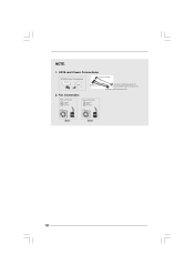
SATA and Power Connections Connect to ODD SATA & Power Connections HDD ODD Connect to HDD Connect to SATA Connector (11) Connect to ATX5V Power Connector (12) Connect to SATA Connector (13) 2. NOTE. 1. Fan Connection Fan connector Ground +12V Rotation Fan connector Ground +5V Rotation item 4 item 6 10
SATA and Power Connections Connect to ODD SATA & Power Connections HDD ODD Connect to HDD Connect to SATA Connector (11) Connect to ATX5V Power Connector (12) Connect to SATA Connector (13) 2. NOTE. 1. Fan Connection Fan connector Ground +12V Rotation Fan connector Ground +5V Rotation item 4 item 6 10
User Manual
Page 15
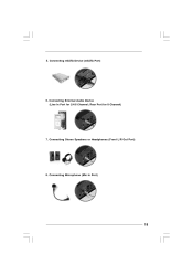
5. Connecting Stereo Speakers or Headphones (Front L/R Out Port) 8. Rear Port for 2/4/6 Channel; Connecting Microphone (Mic In Port) 15 Connecting eSATA Device (eSATA Port) 6. Connecting External Audio Device (Line In Port for 8 Channel) 7.
5. Connecting Stereo Speakers or Headphones (Front L/R Out Port) 8. Rear Port for 2/4/6 Channel; Connecting Microphone (Mic In Port) 15 Connecting eSATA Device (eSATA Port) 6. Connecting External Audio Device (Line In Port for 8 Channel) 7.

User Manual
Page 22
Then, the drivers compatible to your system can work properly. 22 Please follow the order from up to bottom side to your optical drive first. Therefore, the drivers you install can be auto-detected and listed on the support CD driver page. Chapter 5 Driver Installation To install the drivers to your system, please insert the support CD to install those required drivers.
Then, the drivers compatible to your system can work properly. 22 Please follow the order from up to bottom side to your optical drive first. Therefore, the drivers you install can be auto-detected and listed on the support CD driver page. Chapter 5 Driver Installation To install the drivers to your system, please insert the support CD to install those required drivers.

User Manual
Page 24
... Boot driver from ASRock support CD, or you install Instant Boot. Please follow the instructions on Instant Boot setup page. Select destination location. A. a. Select the start menu folder. You may choose a different folder if you need , and click "Next". Execute the Instant Boot installation program under Windows®. c. b. You may choose a different folder if you need , and click "Next". 24 Click "Next" to get the latest utility and BIOS...
... Boot driver from ASRock support CD, or you install Instant Boot. Please follow the instructions on Instant Boot setup page. Select destination location. A. a. Select the start menu folder. You may choose a different folder if you need , and click "Next". Execute the Instant Boot installation program under Windows®. c. b. You may choose a different folder if you need , and click "Next". 24 Click "Next" to get the latest utility and BIOS...

User Manual
Page 25
... Down" from Windows® "Start menu". When you can choose "Fast Mode", "Regular Mode" or "Disable Instant Boot". After reentering into OS, the system will restart once automatically. Please notice that , please click "Apply" to keep AC power on the desktop, then Instant Boot main menu will find an ASRock Instant Boot icon on the Windows® desktop. After the installation is completed, you need to save...
... Down" from Windows® "Start menu". When you can choose "Fast Mode", "Regular Mode" or "Disable Instant Boot". After reentering into OS, the system will restart once automatically. Please notice that , please click "Apply" to keep AC power on the desktop, then Instant Boot main menu will find an ASRock Instant Boot icon on the Windows® desktop. After the installation is completed, you need to save...

User Manual
Page 33
... plus functions for you. Click the THX icon on the desktop. 6.5 THX T ruStudio PRO Sof tware free bundle TruStudio Software After you install THX audio driver from our support CD, there will be a shortcut shown on the Windows® task bar, you will be auto-removed. Please make sure to connect your system to your required function and freely enjoy the...
... plus functions for you. Click the THX icon on the desktop. 6.5 THX T ruStudio PRO Sof tware free bundle TruStudio Software After you install THX audio driver from our support CD, there will be a shortcut shown on the Windows® task bar, you will be auto-removed. Please make sure to connect your system to your required function and freely enjoy the...
User Manual
Page 36
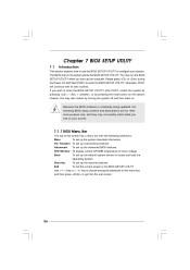
... < > key to choose among the selections on the system chassis. Chapter 7 BIOS SETUP UTILITY 7.1 Introduction This section explains how to use the BIOS SETUP UTILITY to configure your screen. 7.1.1 BIOS Menu Bar The top of the Main OC Tweaker Advanced H/W Monitor Boot screen has a menu bar with its test routines. You may run the BIOS SETUP UTILITY when you wish to enter the BIOS SETUP UTILITY after POST, restart the system by pressing + + , or by turning...
... < > key to choose among the selections on the system chassis. Chapter 7 BIOS SETUP UTILITY 7.1 Introduction This section explains how to use the BIOS SETUP UTILITY to configure your screen. 7.1.1 BIOS Menu Bar The top of the Main OC Tweaker Advanced H/W Monitor Boot screen has a menu bar with its test routines. You may run the BIOS SETUP UTILITY when you wish to enter the BIOS SETUP UTILITY after POST, restart the system by pressing + + , or by turning...
User Manual
Page 41
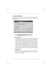
... be turned off Power LED and Lan LED when the system is [Disabled]. 41 This convenient BIOS update tool allows you execute ASRock Instant Flash utility, the utility will also be noted that the USB flash drive or hard drive must use FAT32/16/ 12 file system. 7.4 Advanced Screen In this section, you can update your BIOS only in Flash ROM. CPU Configuration Chipset Configuration ACPI Configuration Storage Configuration USB Configuration BIOS Update Utility ASRock Instant Flash Good Night LED [Disabled] Options for the following items: CPU Configuration, Chipset Configuration, ACPI...
... be turned off Power LED and Lan LED when the system is [Disabled]. 41 This convenient BIOS update tool allows you execute ASRock Instant Flash utility, the utility will also be noted that the USB flash drive or hard drive must use FAT32/16/ 12 file system. 7.4 Advanced Screen In this section, you can update your BIOS only in Flash ROM. CPU Configuration Chipset Configuration ACPI Configuration Storage Configuration USB Configuration BIOS Update Utility ASRock Instant Flash Good Night LED [Disabled] Options for the following items: CPU Configuration, Chipset Configuration, ACPI...

User Manual
Page 42
...; processor that supports Hyper-Threading technology and an operating system that includes optimization for this motherboard. Hyper Threading Technology To enable this feature, it requires a computer system with "No Execute (NX) Memory Protection" can utilize the additional hardware capabilities provided by Vanderpool Technology. The C1 state is set to execute code. Intel (R) Virtualization Tech When this option is supported through the native processor instructions...
...; processor that supports Hyper-Threading technology and an operating system that includes optimization for this motherboard. Hyper Threading Technology To enable this feature, it requires a computer system with "No Execute (NX) Memory Protection" can utilize the additional hardware capabilities provided by Vanderpool Technology. The C1 state is set to execute code. Intel (R) Virtualization Tech When this option is supported through the native processor instructions...
User Manual
Page 47
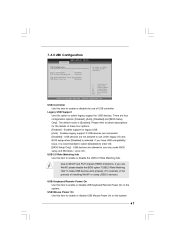
... [Enabled]. 7.4.5 USB Configuration BIOS SETUP UTILITY Advanced USB Configuration USB Controller Legacy USB Support USB 2.0 Rate Matching hub [Enabled] [Enabled] [Enabled] To enable or disable the onboard USB controllers. USB Keyboard/Remote Power On [Disabled] [Disabled] USB Mouse Power On +F1 F9 F10 ESC Select Screen Select Item Change Option General Help Load Defaults Save and Exit Exit v02.54 (C) Copyright 1985-2005, American Megatrends, Inc. USB 2.0 Rate Matching hub Use this item to use under BIOS setup and Windows / Linux OS. There are connected. [Disabled] - Enables...
... [Enabled]. 7.4.5 USB Configuration BIOS SETUP UTILITY Advanced USB Configuration USB Controller Legacy USB Support USB 2.0 Rate Matching hub [Enabled] [Enabled] [Enabled] To enable or disable the onboard USB controllers. USB Keyboard/Remote Power On [Disabled] [Disabled] USB Mouse Power On +F1 F9 F10 ESC Select Screen Select Item Change Option General Help Load Defaults Save and Exit Exit v02.54 (C) Copyright 1985-2005, American Megatrends, Inc. USB 2.0 Rate Matching hub Use this item to use under BIOS setup and Windows / Linux OS. There are connected. [Disabled] - Enables...

User Manual
Page 50
Enter F1 F9 F10 ESC Select Screen Select Item Change General Help Load Defaults Save and Exit Exit v02.54 (C) Copyright 1985-2005, American Megatrends, Inc. 50 BIOS SETUP UTILITY OC Tweaker Advanced H/W Monitor Boot Main Security Exit Security Settings Supervisor Password : Not Installed User Password : Not Installed Change Supervisor Password Change User Password Install or Change the password. For the user password, you may also clear it. 7.7 Security Screen In this section, you may set or change the supervisor/user password for the system.
Enter F1 F9 F10 ESC Select Screen Select Item Change General Help Load Defaults Save and Exit Exit v02.54 (C) Copyright 1985-2005, American Megatrends, Inc. 50 BIOS SETUP UTILITY OC Tweaker Advanced H/W Monitor Boot Main Security Exit Security Settings Supervisor Password : Not Installed User Password : Not Installed Change Supervisor Password Change User Password Install or Change the password. For the user password, you may also clear it. 7.7 Security Screen In this section, you may set or change the supervisor/user password for the system.

User Manual
Page 52
If the Main Menu did not appear automatically, locate and double click on a specific item then follow the installation wizard to visit ASRock's website at http://www.asrock.com; or you need to contact ASRock or want to activate the devices. 8 . 2 . 3 Utilities Menu The Utilities Menu shows the applications software that enhance the system features. 8 . 2 . 1 Running The Support CD To begin using the support CD, insert the CD into...
If the Main Menu did not appear automatically, locate and double click on a specific item then follow the installation wizard to visit ASRock's website at http://www.asrock.com; or you need to contact ASRock or want to activate the devices. 8 . 2 . 3 Utilities Menu The Utilities Menu shows the applications software that enhance the system features. 8 . 2 . 1 Running The Support CD To begin using the support CD, insert the CD into...
Quick Installation Guide
Page 1
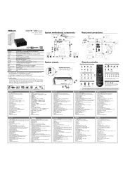
...support driver DVD. 2. SO.are (Mal Vera.) Accessories rpm en [mac= .1•4 Ammer cm =comma mmmboroMfm Ammem. • Krm,mr,...mmmmmmo • Rear panel connections 456. Fhoo=mnoknd MD RATA power.. DC-Inl= B. 0o. Mem speakers or kesiehomes 1B. °SATAN connector 13. Um in = Core...; D. LIM PCI lememe Olt 15X: XVI Off to User Man. MLA,. (R.I Mel. Processor Chipeot Memory VGA HDD ODD Front CO Floor PO Sound LAN WiFi Remote Controller Power Dimension Volume m• .„ 0 m, em- TO play be. For detailed software Introduction, please refer...
...support driver DVD. 2. SO.are (Mal Vera.) Accessories rpm en [mac= .1•4 Ammer cm =comma mmmboroMfm Ammem. • Krm,mr,...mmmmmmo • Rear panel connections 456. Fhoo=mnoknd MD RATA power.. DC-Inl= B. 0o. Mem speakers or kesiehomes 1B. °SATAN connector 13. Um in = Core...; D. LIM PCI lememe Olt 15X: XVI Off to User Man. MLA,. (R.I Mel. Processor Chipeot Memory VGA HDD ODD Front CO Floor PO Sound LAN WiFi Remote Controller Power Dimension Volume m• .„ 0 m, em- TO play be. For detailed software Introduction, please refer...

Quick Installation Guide
Page 2
....SonSfleSse 1. Connecting HDMI Device (HDMI Port) 8 Connecting Microphone (Mk in advance. To change your required ODD / HDD. . ..,_ 3. Replace the side cover and fasten the screws. Connecting Center / Subwoofer Speakers (Center/LEE Port) 11. Slide the side cover toward the rear panel and pull the side cover upwards. Power on the motherboard. 00111lik÷ -4,..,. 46. To install the second HDD, please follow above steps to place the new ODD / HDD to the top HDD. Pull ODD / HDD rack...
....SonSfleSse 1. Connecting HDMI Device (HDMI Port) 8 Connecting Microphone (Mk in advance. To change your required ODD / HDD. . ..,_ 3. Replace the side cover and fasten the screws. Connecting Center / Subwoofer Speakers (Center/LEE Port) 11. Slide the side cover toward the rear panel and pull the side cover upwards. Power on the motherboard. 00111lik÷ -4,..,. 46. To install the second HDD, please follow above steps to place the new ODD / HDD to the top HDD. Pull ODD / HDD rack...


