User Manual
Page 10
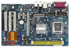
...CTR BASS Top: LINE IN Center: FRONT Bottom: MIC IN Gigabit LAN 30 29 28 27 26 7.1CH HD LAN PHY Super I/O PCI EXPRESS PCIE1 ConRoe1333-GLAN PCIE2 PCIE3 CMOS Battery 1 CLRCMOS1 IDE1 4Mb BIOS HDMI_SPDIF1 1 AUDIO CODEC CD1 HD_AUDIO1 1 GAME1 1 PCI1 PCI2 RoHS PCI3 FLOPPY1 Intel ICH7 USB45 1 CHA_FAN1...PORT1) SATAII_4 (PORT3) SATAII 7 8 9 10 11 12 13 14 15 16 1 PS2_USB_PWR1 Jumper 2 ATX 12V Connector (ATX12V1) 3 ATX Power Connector (ATXPWR1) 4 775-Pin CPU Socket 5 North Bridge Controller 6 CPU Fan Connector (CPU_FAN1) 7 2 x 240-pin DDRII DIMM Slots (Dual Channel: DDRII_1, DDRII_2;
...CTR BASS Top: LINE IN Center: FRONT Bottom: MIC IN Gigabit LAN 30 29 28 27 26 7.1CH HD LAN PHY Super I/O PCI EXPRESS PCIE1 ConRoe1333-GLAN PCIE2 PCIE3 CMOS Battery 1 CLRCMOS1 IDE1 4Mb BIOS HDMI_SPDIF1 1 AUDIO CODEC CD1 HD_AUDIO1 1 GAME1 1 PCI1 PCI2 RoHS PCI3 FLOPPY1 Intel ICH7 USB45 1 CHA_FAN1...PORT1) SATAII_4 (PORT3) SATAII 7 8 9 10 11 12 13 14 15 16 1 PS2_USB_PWR1 Jumper 2 ATX 12V Connector (ATX12V1) 3 ATX Power Connector (ATXPWR1) 4 775-Pin CPU Socket 5 North Bridge Controller 6 CPU Fan Connector (CPU_FAN1) 7 2 x 240-pin DDRII DIMM Slots (Dual Channel: DDRII_1, DDRII_2;

User Manual
Page 13
...degrees. Step 1-3. Rotate the load plate to fully open position at approximately 100 degrees. Hold the CPU by depressing down and out on the socket. Step 2-2. Otherwise, the CPU will be seriously damaged. Step 1-2. Pin1 orientation key notch orientation key notch Pin1 alignment key alignment ...key 775-LAND CPU 775-Pin Socket 13 black line black line Open the socket: Step 1-1. Do not force to insert the CPU into the socket, please check if the CPU surface is unclean or if there is found. Insert the 775...
...degrees. Step 1-3. Rotate the load plate to fully open position at approximately 100 degrees. Hold the CPU by depressing down and out on the socket. Step 2-2. Otherwise, the CPU will be seriously damaged. Step 1-2. Pin1 orientation key notch orientation key notch Pin1 alignment key alignment ...key 775-LAND CPU 775-Pin Socket 13 black line black line Open the socket: Step 1-1. Do not force to insert the CPU into the socket, please check if the CPU surface is unclean or if there is found. Insert the 775...

User Manual
Page 14
...must be placed if returning the motherboard for after service. Step 4. Step 4-2. Close the socket: Step 4-1. Step 2-3. Step 4-3. For proper inserting, please ensure to match the two orientation key notches of the CPU with load plate tab under retention tab of load lever. 14 Rotate the load plate ...onto the IHS. Carefully place the CPU into the socket by using a purely vertical motion. It is within the socket and properly mated to the orient keys....
...must be placed if returning the motherboard for after service. Step 4. Step 4-2. Close the socket: Step 4-1. Step 2-3. Step 4-3. For proper inserting, please ensure to match the two orientation key notches of the CPU with load plate tab under retention tab of load lever. 14 Rotate the load plate ...onto the IHS. Carefully place the CPU into the socket by using a purely vertical motion. It is within the socket and properly mated to the orient keys....

User Manual
Page 15
... remaining fasteners. Repeat with fan operation or contact other . Before you installed the heatsink, you press down on fastener caps with 775-Pin socket that the CPU and the heatsink are oriented on side closest to the instruction manuals of IHS on the motherboard (CPU_FAN1, see page 10, No. 6). ...For proper installation, please kindly refer to the CPU fan connector on the socket surface. Apply thermal interface material onto center of your CPU fan and heatsink. Place the heatsink onto the...
... remaining fasteners. Repeat with fan operation or contact other . Before you installed the heatsink, you press down on fastener caps with 775-Pin socket that the CPU and the heatsink are oriented on side closest to the instruction manuals of IHS on the motherboard (CPU_FAN1, see page 10, No. 6). ...For proper installation, please kindly refer to the CPU fan connector on the socket surface. Apply thermal interface material onto center of your CPU fan and heatsink. Place the heatsink onto the...

Quick Installation Guide
Page 2
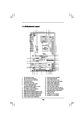
Motherboard Layout English 1 PS2_USB_PWR1 Jumper 2 ATX 12V Connector (ATX12V1) 3 ATX Power Connector (ATXPWR1) 4 775-Pin CPU Socket 5 North Bridge Controller 6 CPU Fan Connector (CPU_FAN1) 7 2 x 240-pin DDRII DIMM Slots (Dual Channel: DDRII_1, DDRII_2; Red) 14 SATAII Connector (SATAII_1 (PORT0); Orange) 12 SATAII...) 27 PCI Slots (PCI1- 3) 28 BIOS FWH Chip 29 PCI Express x1 Slot (PCIE3) 30 PCI Express x1 Slot (PCIE2) 2 ASRock ConRoe1333-GLAN Motherboard Yellow) 8 PCI Express x16 Slot (PCIE1) 9 Clear CMOS Jumper (CLRCMOS1) 10 IDE1 Connector (IDE1, Blue) 11 SATAII Connector (SATAII_3 (PORT2);
Motherboard Layout English 1 PS2_USB_PWR1 Jumper 2 ATX 12V Connector (ATX12V1) 3 ATX Power Connector (ATXPWR1) 4 775-Pin CPU Socket 5 North Bridge Controller 6 CPU Fan Connector (CPU_FAN1) 7 2 x 240-pin DDRII DIMM Slots (Dual Channel: DDRII_1, DDRII_2; Red) 14 SATAII Connector (SATAII_1 (PORT0); Orange) 12 SATAII...) 27 PCI Slots (PCI1- 3) 28 BIOS FWH Chip 29 PCI Express x1 Slot (PCIE3) 30 PCI Express x1 Slot (PCIE2) 2 ASRock ConRoe1333-GLAN Motherboard Yellow) 8 PCI Express x16 Slot (PCIE1) 9 Clear CMOS Jumper (CLRCMOS1) 10 IDE1 Connector (IDE1, Blue) 11 SATAII Connector (SATAII_3 (PORT2);

Quick Installation Guide
Page 9
... handle components. 3. Unplug the power cord from the wall socket before you insert the 775-LAND CPU into the screw holes to secure the motherboard to insert the CPU into the socket if above situation is any component. Otherwise, the CPU will be seriously damaged. 9 ASRock ConRoe1333-GLAN Motherboard English Do not force to the chassis, please do...
... handle components. 3. Unplug the power cord from the wall socket before you insert the 775-LAND CPU into the screw holes to secure the motherboard to insert the CPU into the socket if above situation is any component. Otherwise, the CPU will be seriously damaged. 9 ASRock ConRoe1333-GLAN Motherboard English Do not force to the chassis, please do...

Quick Installation Guide
Page 10
... at approximately 135 degrees. Rotate the load lever to assist in removal. 10 ASRock ConRoe1333-GLAN Motherboard Step 1-3. Step 2. Orient the CPU with right hand thumb and peel the cap from the socket while pressing on the hook to fully open position at approximately 100 degrees. Step... 2-1. Pin1 orientation key notch orientation key notch Pin1 alignment key alignment key 775-LAND CPU 775-Pin Socket For proper inserting, please ensure to the orient keys. Open the socket: Step 1-1. Rotate the load plate to clear retention tab. Remove PnP Cap (Pick ...
... at approximately 135 degrees. Rotate the load lever to assist in removal. 10 ASRock ConRoe1333-GLAN Motherboard Step 1-3. Step 2. Orient the CPU with right hand thumb and peel the cap from the socket while pressing on the hook to fully open position at approximately 100 degrees. Step... 2-1. Pin1 orientation key notch orientation key notch Pin1 alignment key alignment key 775-LAND CPU 775-Pin Socket For proper inserting, please ensure to the orient keys. Open the socket: Step 1-1. Rotate the load plate to clear retention tab. Remove PnP Cap (Pick ...

Quick Installation Guide
Page 11
... Step 6. Secure load lever with fan operation or contact other components. 11 ASRock ConRoe1333-GLAN Motherboard English Step 4. Rotate the fastener clockwise, then press down lightly on fastener caps with the CPU fan connector on the motherboard. 1. Step 3. If you press down the fasteners...returning the motherboard for 775-LAND CPU. Step 4-3. Align fasteners with remaining fasteners. Repeat with the motherboard throughholes. Connect fan header with thumb to the CPU fan connector on the socket surface. Place the heatsink onto the socket. This cap must be secured...
... Step 6. Secure load lever with fan operation or contact other components. 11 ASRock ConRoe1333-GLAN Motherboard English Step 4. Rotate the fastener clockwise, then press down lightly on fastener caps with the CPU fan connector on the motherboard. 1. Step 3. If you press down the fasteners...returning the motherboard for 775-LAND CPU. Step 4-3. Align fasteners with remaining fasteners. Repeat with the motherboard throughholes. Connect fan header with thumb to the CPU fan connector on the socket surface. Place the heatsink onto the socket. This cap must be secured...


