
User Manual
Page 3
... of Memory Modules (DIMM 16 2.6 Expansion Slots (PCI, HDMR, and PCI Express Slots) ....... 17 2.7 Jumpers Setup 18 2.8 Onboard Headers and Connectors 19 2.9 SATAII Hard Disk Setup Guide 23 2.10 Serial ATA (SATA) / Serial ATAII (SATAII) Hard Disks Installation 24 2.11 Driver Installation Guide 24 2.12 HDMR Card and Driver Installation 24 2.13 Untied Overclocking Technology 24 3 BIOS SETUP UTILITY 25 3.1 Introduction 25 3.1.1 BIOS Menu Bar 25 3.1.2 Navigation Keys 26 3.2 Main Screen 26 3.3 Advanced Screen 26 3.3.1 CPU Configuration 27 3.3.2 Chipset Configuration 29 3.3.3 ACPI...
... of Memory Modules (DIMM 16 2.6 Expansion Slots (PCI, HDMR, and PCI Express Slots) ....... 17 2.7 Jumpers Setup 18 2.8 Onboard Headers and Connectors 19 2.9 SATAII Hard Disk Setup Guide 23 2.10 Serial ATA (SATA) / Serial ATAII (SATAII) Hard Disks Installation 24 2.11 Driver Installation Guide 24 2.12 HDMR Card and Driver Installation 24 2.13 Untied Overclocking Technology 24 3 BIOS SETUP UTILITY 25 3.1 Introduction 25 3.1.1 BIOS Menu Bar 25 3.1.2 Navigation Keys 26 3.2 Main Screen 26 3.3 Advanced Screen 26 3.3.1 CPU Configuration 27 3.3.2 Chipset Configuration 29 3.3.3 ACPI...
User Manual
Page 8
... CPU bus frequencies may be overclocked to perform over-clocking. Frequencies other than 4GB for the reservation for USB 2.0 works fine under Windows® XP, Windows® XP 64-bit, Windows® VistaTM and Windows® VistaTM 64-bit. 7. Before you implement Dual Channel Memory Technology, make sure to read the "SATAII Hard Disk Setup Guide" on this motherboard, it is detected, the system will automatically shutdown. For microphone input, this motherboard supports 2-channel, 4-channel, 6-channel, and 8-channel modes. For audio...
... CPU bus frequencies may be overclocked to perform over-clocking. Frequencies other than 4GB for the reservation for USB 2.0 works fine under Windows® XP, Windows® XP 64-bit, Windows® VistaTM and Windows® VistaTM 64-bit. 7. Before you implement Dual Channel Memory Technology, make sure to read the "SATAII Hard Disk Setup Guide" on this motherboard, it is detected, the system will automatically shutdown. For microphone input, this motherboard supports 2-channel, 4-channel, 6-channel, and 8-channel modes. For audio...
User Manual
Page 10
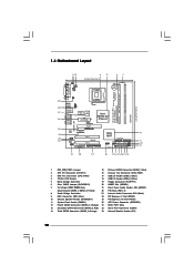
...2 ATX 12V Connector (ATX12V1) 16 Chassis Fan Connector (CHA_FAN1) 3 CPU Fan Connector (CPU_FAN1) 17 USB 2.0 Header (USB6_7, Blue) 4 775-Pin CPU Socket 18 USB 2.0 Header (USB4_5, Blue) 5 North Bridge Controller 19 Floppy Connector (FLOPPY1) 6 Clear CMOS Jumper (CLRCMOS1) 20 HDMR Slot (HDMR1) 7 2 x 240-pin DDRII DIMM Slots 21 Front Panel Audio Header (HD_AUDIO1) (Dual Channel: DDRII_1, DDRII_3; Yellow) 22 PCI Slots (PCI1- 2) 8 South Bridge Controller 23 Internal Audio Connector: CD1 (Black) 9 IDE1 Connector (IDE1, Blue) 24 PCI Express x1 Slot (PCIE2) 10 Chassis Speaker...
...2 ATX 12V Connector (ATX12V1) 16 Chassis Fan Connector (CHA_FAN1) 3 CPU Fan Connector (CPU_FAN1) 17 USB 2.0 Header (USB6_7, Blue) 4 775-Pin CPU Socket 18 USB 2.0 Header (USB4_5, Blue) 5 North Bridge Controller 19 Floppy Connector (FLOPPY1) 6 Clear CMOS Jumper (CLRCMOS1) 20 HDMR Slot (HDMR1) 7 2 x 240-pin DDRII DIMM Slots 21 Front Panel Audio Header (HD_AUDIO1) (Dual Channel: DDRII_1, DDRII_3; Yellow) 22 PCI Slots (PCI1- 2) 8 South Bridge Controller 23 Internal Audio Connector: CD1 (Black) 9 IDE1 Connector (IDE1, Blue) 24 PCI Express x1 Slot (PCIE2) 10 Chassis Speaker...
User Manual
Page 20
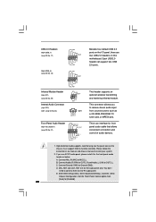
... front panel audio header as a CD-ROM, DVD-ROM, TV tuner card, or MPEG card. Enter BIOS Setup Utility. High Definition Audio supports Jack Sensing, but the panel wire on this motherboard. This connector allows you use AC'97 audio panel, please install it to function correctly. USB 2.0 Headers (9-pin USB6_7) (see p.10 No. 17) USB_PWR P-7 P+7 GND DUMMY 1 GND P+6 P-6 USB_PWR Besides four default USB 2.0 ports on the I/O panel, there are for HD audio panel only. Please follow the instruction in our manual and chassis manual to...
... front panel audio header as a CD-ROM, DVD-ROM, TV tuner card, or MPEG card. Enter BIOS Setup Utility. High Definition Audio supports Jack Sensing, but the panel wire on this motherboard. This connector allows you use AC'97 audio panel, please install it to function correctly. USB 2.0 Headers (9-pin USB6_7) (see p.10 No. 17) USB_PWR P-7 P+7 GND DUMMY 1 GND P+6 P-6 USB_PWR Besides four default USB 2.0 ports on the I/O panel, there are for HD audio panel only. Please follow the instruction in our manual and chassis manual to...

User Manual
Page 24
... insert the support CD to the motherboard's SATAII connector. STEP 4: Connect the other end of the SATA data cable to your chassis. Therefore, the drivers you enable Untied Overclocking function, please enter "Overclock Mode" option of your optical drive first. Reboot your system. 2.13 Untied Overclocking Technology This motherboard supports Untied Overclocking Technology, which means during overclocking, but PCI / PCIE buses are in the fixed mode so that FSB can work properly. 2.12 HDMR Card and Driver Installation If...
... insert the support CD to the motherboard's SATAII connector. STEP 4: Connect the other end of the SATA data cable to your chassis. Therefore, the drivers you enable Untied Overclocking function, please enter "Overclock Mode" option of your optical drive first. Reboot your system. 2.13 Untied Overclocking Technology This motherboard supports Untied Overclocking Technology, which means during overclocking, but PCI / PCIE buses are in the fixed mode so that FSB can work properly. 2.12 HDMR Card and Driver Installation If...
User Manual
Page 27
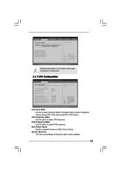
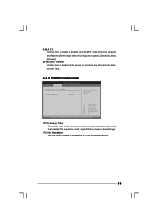
...malfunction. 3.3.1 CPU Configuration BIOS SETUP UTILITY Advanced CPU Configuration Overclock Mode CPU Frequency (MHz) PCIE Frequency (MHz) Boot Failure Guard Spread Spectrum Ratio Actual Value [Auto] [200] [100] [Enabled] [Auto] 17 Enhance Halt State Max CPUID Value Limit Intel (R) Virtualization tech. The default value is [Auto]. CPU Configuration Chipset Configuration ACPI Configuration IDE Configuration PCIPnP Configuration Floppy Configuration SuperIO Configuration USB Configuration Configure CPU Select Screen Select Item Enter Go to Sub Screen F1 General Help F9 Load Defaults F10...
...malfunction. 3.3.1 CPU Configuration BIOS SETUP UTILITY Advanced CPU Configuration Overclock Mode CPU Frequency (MHz) PCIE Frequency (MHz) Boot Failure Guard Spread Spectrum Ratio Actual Value [Auto] [200] [100] [Enabled] [Auto] 17 Enhance Halt State Max CPUID Value Limit Intel (R) Virtualization tech. The default value is [Auto]. CPU Configuration Chipset Configuration ACPI Configuration IDE Configuration PCIPnP Configuration Floppy Configuration SuperIO Configuration USB Configuration Configure CPU Select Screen Select Item Enter Go to Sub Screen F1 General Help F9 Load Defaults F10...
User Manual
Page 28
... the installed CPU does not support Intel (R) Virtualization Technology. This option will find this item appear to allow you changing the ratio value of the system caches. Set to execute code. Enhance Halt State All processors support the Halt State (C1). If it requires a computer system with "No Execute (NX) Memory Protection" can utilize the additional hardware capabilities provided by malicious software to [Enabled] if using...
... the installed CPU does not support Intel (R) Virtualization Technology. This option will find this item appear to allow you changing the ratio value of the system caches. Set to execute code. Enhance Halt State All processors support the Halt State (C1). If it requires a computer system with "No Execute (NX) Memory Protection" can utilize the additional hardware capabilities provided by malicious software to [Enabled] if using...
User Manual
Page 29
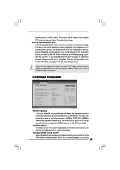
...Internal Graphics Mode Select DVMT Mode Select DVMT/FIXED Memory [PCI] [Auto] [DVMT Mode] [Maximum DVMT] OnBoard HD Audio Front Panel CD-In OnBoard Lan [Auto] [Auto] [Enabled] [Enabled] PCI Fix Function VCCM Voltage [Enabled] [Auto] Options Auto 200MHz 266MHz 333MHz (DDRII400) (DDRII533) (DDRII667) +F1 F9 F10 ESC Select Screen Select Item Change Option General Help Load Defaults Save and Exit Exit v02.54 (C) Copyright 1985-2005, American Megatrends, Inc. Configuration options: [Auto], [Enabled] and [Disabled]. Flexibility Option The default value of the CPU you install Windows...
...Internal Graphics Mode Select DVMT Mode Select DVMT/FIXED Memory [PCI] [Auto] [DVMT Mode] [Maximum DVMT] OnBoard HD Audio Front Panel CD-In OnBoard Lan [Auto] [Auto] [Enabled] [Enabled] PCI Fix Function VCCM Voltage [Enabled] [Auto] Options Auto 200MHz 266MHz 333MHz (DDRII400) (DDRII533) (DDRII667) +F1 F9 F10 ESC Select Screen Select Item Change Option General Help Load Defaults Save and Exit Exit v02.54 (C) Copyright 1985-2005, American Megatrends, Inc. Configuration options: [Auto], [Enabled] and [Disabled]. Flexibility Option The default value of the CPU you install Windows...

User Manual
Page 30
... DRAM Clocks]. Internal Graphics Mode Select If you install VGA card; In DVMT mode, the graphics driver allocates memory as needed for the motherboard through efficient memory utilization. the items "DRAM RAS# to CAS# Delay", "DRAM RAS# Precharge", and "DRAM RAS# Activate to Precharge" appear to allow you select [Enabled, 8MB] or [Enabled, 1MB], the onboard VGA will be enabled. Configuration options: [2 DRAM Clocks], [3 DRAM Clocks], [4 DRAM Clocks], [5 DRAM Clocks], and [6 DRAM Clocks]. DVMT (Dynamic Video Memory Technology) is an architecture that at least 64MB of memory accessing...
... DRAM Clocks]. Internal Graphics Mode Select If you install VGA card; In DVMT mode, the graphics driver allocates memory as needed for the motherboard through efficient memory utilization. the items "DRAM RAS# to CAS# Delay", "DRAM RAS# Precharge", and "DRAM RAS# Activate to Precharge" appear to allow you select [Enabled, 8MB] or [Enabled, 1MB], the onboard VGA will be enabled. Configuration options: [2 DRAM Clocks], [3 DRAM Clocks], [4 DRAM Clocks], [5 DRAM Clocks], and [6 DRAM Clocks]. DVMT (Dynamic Video Memory Technology) is an architecture that at least 64MB of memory accessing...
User Manual
Page 31
... to use this motherboard to enable or disable the "OnBoard Lan" feature. Configuration options: [High], [Normal], [Low], and [Auto]. The default value of OnBoard HD Audio. PCI Fix Function This allows you to submit Windows® VistaTM logo test, please disable this feature is plugged. OnBoard HD Audio Select [Auto], [Enabled] or [Disabled] for the onboard HD Audio Front Panel. If this item is set to [Disabled], PCI clock can be fixed at 33.3 MHz. VDDQ Voltage Configuration options: [High], [Low] and [Auto]. OnBoard Lan This...
... to use this motherboard to enable or disable the "OnBoard Lan" feature. Configuration options: [High], [Normal], [Low], and [Auto]. The default value of OnBoard HD Audio. PCI Fix Function This allows you to submit Windows® VistaTM logo test, please disable this feature is plugged. OnBoard HD Audio Select [Auto], [Enabled] or [Disabled] for the onboard HD Audio Front Panel. If this item is set to [Disabled], PCI clock can be fixed at 33.3 MHz. VDDQ Voltage Configuration options: [High], [Low] and [Auto]. OnBoard Lan This...
User Manual
Page 35
... cards' specifications require other settings. Configuration options: [Disabled], [Auto], [Enabled]. 32-Bit Data Transfer Use this item to enable or disable the PCI IDE BusMaster feature. 35 PCI Latency Timer The default value is recommended to maximize the IDE hard disk data transfer rate. 3.3.5 PCIPnP Configuration BIOS SETUP UTILITY Advanced Advanced PCI / PnP Settings PCI Latency Timer PCI IDE BusMaster [32] [Enabled] Value in units of PCI clocks for PCI device latency timer register. +F1 F9 F10 ESC Select Screen Select Item Change Option General Help Load Defaults...
... cards' specifications require other settings. Configuration options: [Disabled], [Auto], [Enabled]. 32-Bit Data Transfer Use this item to enable or disable the PCI IDE BusMaster feature. 35 PCI Latency Timer The default value is recommended to maximize the IDE hard disk data transfer rate. 3.3.5 PCIPnP Configuration BIOS SETUP UTILITY Advanced Advanced PCI / PnP Settings PCI Latency Timer PCI IDE BusMaster [32] [Enabled] Value in units of PCI clocks for PCI device latency timer register. +F1 F9 F10 ESC Select Screen Select Item Change Option General Help Load Defaults...
User Manual
Page 36
BIOS SETUP UTILITY Advanced Floppy Configuration Floppy A [1.44 MB 312"] Select the type of your floppy drive. Infrared Port Address Use this item to set the address for the onboard serial port or disable it . 3.3.6 Floppy Configuration In this item to enable or disable floppy drive controller. Serial Port Address Use this item to Enable or Disable Floppy Controller. +F1 F9 F10 ESC Select Screen Select Item Change Option General Help Load Defaults Save and Exit Exit v02.54 (C) Copyright 1985-2005, American Megatrends, Inc. OnBoard Floppy Controller Use this...
BIOS SETUP UTILITY Advanced Floppy Configuration Floppy A [1.44 MB 312"] Select the type of your floppy drive. Infrared Port Address Use this item to set the address for the onboard serial port or disable it . 3.3.6 Floppy Configuration In this item to enable or disable floppy drive controller. Serial Port Address Use this item to Enable or Disable Floppy Controller. +F1 F9 F10 ESC Select Screen Select Item Change Option General Help Load Defaults Save and Exit Exit v02.54 (C) Copyright 1985-2005, American Megatrends, Inc. OnBoard Floppy Controller Use this...
User Manual
Page 37
...], [DMA1], and [DMA3]. USB Controller Use this item to enable or disable the USB 2.0 support. Or you may select [Auto] so that the system will start to set the address for the parallel port. Configuration options: [Disabled], [378], and [278]. Configuration options: [IRQ5] and [IRQ7]. 3.3.8 USB Configuration BIOS SETUP UTILITY Advanced USB Configuration USB Controller USB 2.0 Support Legacy USB Support [Enabled] [Enabled] [Disabled] To enable or disable the onboard USB controllers. +F1 F9 F10 ESC Select Screen Select Item Change Option General Help Load Defaults Save and Exit Exit...
...], [DMA1], and [DMA3]. USB Controller Use this item to enable or disable the USB 2.0 support. Or you may select [Auto] so that the system will start to set the address for the parallel port. Configuration options: [Disabled], [378], and [278]. Configuration options: [IRQ5] and [IRQ7]. 3.3.8 USB Configuration BIOS SETUP UTILITY Advanced USB Configuration USB Controller USB 2.0 Support Legacy USB Support [Enabled] [Enabled] [Disabled] To enable or disable the onboard USB controllers. +F1 F9 F10 ESC Select Screen Select Item Change Option General Help Load Defaults Save and Exit Exit...

User Manual
Page 42
... with the motherboard contains necessary drivers and useful utilities that the motherboard supports. or you need to contact ASRock or want to your CD-ROM drive. The CD automatically displays the Main Menu if "AUTORUN" is enabled in this chapter for further information. 42 Because motherboard settings and hardware options vary, use the setup procedures in your dealer for general reference only. Chapter 4 Software Support 4.1 Install Operating System This motherboard supports various Microsoft...
... with the motherboard contains necessary drivers and useful utilities that the motherboard supports. or you need to contact ASRock or want to your CD-ROM drive. The CD automatically displays the Main Menu if "AUTORUN" is enabled in this chapter for further information. 42 Because motherboard settings and hardware options vary, use the setup procedures in your dealer for general reference only. Chapter 4 Software Support 4.1 Install Operating System This motherboard supports various Microsoft...

Quick Installation Guide
Page 7
... system or damage the CPU. 8. sponding memory support frequency. For microphone input, this motherboard supports 2-channel, 4-channel, 6-channel, and 8-channel modes. As long as we have the latest driver, we will automatically shutdown. This motherboard supports Untied Overclocking Technology. Please check the table below for Microsoft® Windows® VistaTM / VistaTM 64-bit driver and related information. You can also connect SATA hard disk to perform over-clocking. ASRock website http://www.asrock.com 7 ASRock ConRoe1333-D667 Motherboard English Microsoft®...
... system or damage the CPU. 8. sponding memory support frequency. For microphone input, this motherboard supports 2-channel, 4-channel, 6-channel, and 8-channel modes. As long as we have the latest driver, we will automatically shutdown. This motherboard supports Untied Overclocking Technology. Please check the table below for Microsoft® Windows® VistaTM / VistaTM 64-bit driver and related information. You can also connect SATA hard disk to perform over-clocking. ASRock website http://www.asrock.com 7 ASRock ConRoe1333-D667 Motherboard English Microsoft®...
Quick Installation Guide
Page 13
... 2 PCI slots, 1 HDMR slot and 2 PCI Express slots on PCI Express VGA card to use . Installing an expansion card Step 1. Step 4. Fasten the card to install expansion cards that the power supply is switched off or the power cord is completely seated on PCI Express VGA card to PCIE1 (PCIE x16 slot) and adjust the "Internal Graphics Mode Select" BIOS option to insert a HDMR card with v.92 Modem functionality. If you start the installation. 2.4 Expansion Slots (PCI, HDMR and PCI Express Slots) There are used to the chassis with screws. 13 ASRock ConRoe1333-D667 Motherboard...
... 2 PCI slots, 1 HDMR slot and 2 PCI Express slots on PCI Express VGA card to use . Installing an expansion card Step 1. Step 4. Fasten the card to install expansion cards that the power supply is switched off or the power cord is completely seated on PCI Express VGA card to PCIE1 (PCIE x16 slot) and adjust the "Internal Graphics Mode Select" BIOS option to insert a HDMR card with v.92 Modem functionality. If you start the installation. 2.4 Expansion Slots (PCI, HDMR and PCI Express Slots) There are used to the chassis with screws. 13 ASRock ConRoe1333-D667 Motherboard...

Quick Installation Guide
Page 16
... module. Infrared Module Header (5-pin IR1) (see p.2 No. 29) Internal Audio Connector (4-pin CD1) (CD1: see p.2 No. 23) Front Panel Audio Header (9-pin HD_AUDIO1) (see p.2 No. 18) Besides four default USB 2.0 ports on the I/O panel, there are for front panel audio cable that allows convenient connection and control of audio devices. 1. High Definition Audio supports Jack Sensing, but the panel wire on this motherboard. You don't need to [Enabled]. 16 ASRock ConRoe1333-D667 Motherboard English Set the Front Panel Control option from sound sources such as below...
... module. Infrared Module Header (5-pin IR1) (see p.2 No. 29) Internal Audio Connector (4-pin CD1) (CD1: see p.2 No. 23) Front Panel Audio Header (9-pin HD_AUDIO1) (see p.2 No. 18) Besides four default USB 2.0 ports on the I/O panel, there are for front panel audio cable that allows convenient connection and control of audio devices. 1. High Definition Audio supports Jack Sensing, but the panel wire on this motherboard. You don't need to [Enabled]. 16 ASRock ConRoe1333-D667 Motherboard English Set the Front Panel Control option from sound sources such as below...

Quick Installation Guide
Page 19
... run at SATAII mode, which operate with different vendors to enable SATAII function, please follow the below SATAII hard disk setup guide. HITACHI Please use the Feature Tool, a DOS-bootable tool, for the updates. 19 ASRock ConRoe1333-D667 Motherboard English Western Digital If pin 5 and pin 6 are shorted, SATA 1.5Gb/s will be the same. Please visit HITACHI's website for details: http://www.hitachigst.com/hdd/support/download.htm The...
... run at SATAII mode, which operate with different vendors to enable SATAII function, please follow the below SATAII hard disk setup guide. HITACHI Please use the Feature Tool, a DOS-bootable tool, for the updates. 19 ASRock ConRoe1333-D667 Motherboard English Western Digital If pin 5 and pin 6 are shorted, SATA 1.5Gb/s will be the same. Please visit HITACHI's website for details: http://www.hitachigst.com/hdd/support/download.htm The...
Quick Installation Guide
Page 20
... finish installing all drivers to [CPU, PCIE, Async.]. STEP 4: Connect the other end of BIOS setup to set the selection from our support CD to install the SATA / SATAII hard disks. Then, the drivers compatible to your system. 2.11 Untied Overclocking Technology This motherboard supports Untied Overclocking Technology, which means during overclocking, but in the fixed mode so that the HDMR card is untied during overclocking, FSB enjoys better margin due to HDMR slot on this motherboard...
... finish installing all drivers to [CPU, PCIE, Async.]. STEP 4: Connect the other end of BIOS setup to set the selection from our support CD to install the SATA / SATAII hard disks. Then, the drivers compatible to your system. 2.11 Untied Overclocking Technology This motherboard supports Untied Overclocking Technology, which means during overclocking, but in the fixed mode so that the HDMR card is untied during overclocking, FSB enjoys better margin due to HDMR slot on this motherboard...

Quick Installation Guide
Page 21
... the motherboard contains necessary drivers and useful utilities that will display the Main Menu automatically if "AUTORUN" is enabled in your CD-ROM drive. It will enhance motherboard features. EXE" from the BIN folder in the Support CD. 4. BIOS Information The Flash Memory on the file "ASSETUP. When you to scroll through its test routines. It is designed to the User Manual (PDF file) contained in the Support CD to enter BIOS Setup after POST...
... the motherboard contains necessary drivers and useful utilities that will display the Main Menu automatically if "AUTORUN" is enabled in your CD-ROM drive. It will enhance motherboard features. EXE" from the BIN folder in the Support CD. 4. BIOS Information The Flash Memory on the file "ASSETUP. When you to scroll through its test routines. It is designed to the User Manual (PDF file) contained in the Support CD to enter BIOS Setup after POST...


