
User Manual
Page 3
...Contents 5 1.2 Specifications 6 1.3 Minimum Hardware Requirement Table for Windows® VistaTM Premium 2007 and Basic Logo 9 1.4 Motherboard Layout 10 1.5 ASRock HD 8CH_1394 I/O 11 2 Installation 12 2.1 Screw Holes 12 2.2 Pre-installation Precautions 12 2.3 CPU Installation 13 2.4 Installation of Heatsink and ...DIMM 16 2.6 Expansion Slots (PCI and PCI Express Slots 18 2.7 Jumpers Setup 19 2.8 Onboard Headers and Connectors 20 2.9 HDMI_SPDIF Header Connection Guide 24 2.10 SATAII Hard Disk Setup Guide 25 2.11 Serial ATA (SATA) / Serial ATAII (SATAII) Hard Disks Installation 26...
...Contents 5 1.2 Specifications 6 1.3 Minimum Hardware Requirement Table for Windows® VistaTM Premium 2007 and Basic Logo 9 1.4 Motherboard Layout 10 1.5 ASRock HD 8CH_1394 I/O 11 2 Installation 12 2.1 Screw Holes 12 2.2 Pre-installation Precautions 12 2.3 CPU Installation 13 2.4 Installation of Heatsink and ...DIMM 16 2.6 Expansion Slots (PCI and PCI Express Slots 18 2.7 Jumpers Setup 19 2.8 Onboard Headers and Connectors 20 2.9 HDMI_SPDIF Header Connection Guide 24 2.10 SATAII Hard Disk Setup Guide 25 2.11 Serial ATA (SATA) / Serial ATAII (SATAII) Hard Disks Installation 26...

User Manual
Page 8
...usage under Microsoft® Windows® VistaTM 64-bit / VistaTM / XP 64-bit / XP SP1 or SP2 / 2000 SP4. 8 You can also connect SATA hard disk to SATAII connector, please read "Untied Overclocking Technology" on page 16 for USB 2.0 works fine under Windows® XP, Windows® ... again. While CPU overheat is not recommended to SATAII mode. Please read the "SATAII Hard Disk Setup Guide" on page 16 for proper connection. 11. Before you install the PC system. 10. Due to the chipset limitation, the actual memory size may cause the instability of memory...
...usage under Microsoft® Windows® VistaTM 64-bit / VistaTM / XP 64-bit / XP SP1 or SP2 / 2000 SP4. 8 You can also connect SATA hard disk to SATAII connector, please read "Untied Overclocking Technology" on page 16 for USB 2.0 works fine under Windows® XP, Windows® ... again. While CPU overheat is not recommended to SATAII mode. Please read the "SATAII Hard Disk Setup Guide" on page 16 for proper connection. 11. Before you install the PC system. 10. Due to the chipset limitation, the actual memory size may cause the instability of memory...

User Manual
Page 11
...computer, you need to connect a front panel audio cable to use 2-channel speaker, please connect the speaker's plug into "Front Speaker Jack". 1.5 ASRock HD 8CH_1394 I/O 1 14 13 12 2 3 4 7 5 8 6 9 11 10 1 Parallel Port 2 IEEE 1394 Port 3 RJ-45 ...audio. 11 Please select "Mixer ToolBox" , click "Enable playback multi-streaming", and click "ok". TABLE for connection details in accordance with the type of speaker you use. See the table below for Audio Output Connection Audio Output Channels Front Speaker Rear Speaker Central / Bass (No. 8) (No. 5) (No. 6) 2 V...
...computer, you need to connect a front panel audio cable to use 2-channel speaker, please connect the speaker's plug into "Front Speaker Jack". 1.5 ASRock HD 8CH_1394 I/O 1 14 13 12 2 3 4 7 5 8 6 9 11 10 1 Parallel Port 2 IEEE 1394 Port 3 RJ-45 ...audio. 11 Please select "Mixer ToolBox" , click "Enable playback multi-streaming", and click "ok". TABLE for connection details in accordance with the type of speaker you use. See the table below for Audio Output Connection Audio Output Channels Front Speaker Rear Speaker Central / Bass (No. 8) (No. 5) (No. 6) 2 V...

User Manual
Page 15
Then connect the CPU fan to the CPU fan connector on the motherboard (CPU_FAN1, see page 10, No. 3). Step 1. Step 2. Align fasteners with remaining fasteners. Ensure fan ... connector on the motherboard. Apply thermal interface material onto center of CPU Fan and Heatsink This motherboard is an example to install and lock. Step 3. Connect fan header with 775-Pin socket that the CPU and the heatsink are oriented on side closest to the CPU_FAN connector (CPU_FAN1, see page 10...
Then connect the CPU fan to the CPU fan connector on the motherboard (CPU_FAN1, see page 10, No. 3). Step 1. Step 2. Align fasteners with remaining fasteners. Ensure fan ... connector on the motherboard. Apply thermal interface material onto center of CPU Fan and Heatsink This motherboard is an example to install and lock. Step 3. Connect fan header with 775-Pin socket that the CPU and the heatsink are oriented on side closest to the CPU_FAN connector (CPU_FAN1, see page 10...

User Manual
Page 20
... support SATAII or SATA hard disk for the details. Primary IDE connector (Blue) (39-pin IDE1, see p.10 No. 10) PIN1 IDE1 connect the blue end connect the black end to the motherboard to the IDE devices 80-conductor ATA 66/100 cable Note: Please refer to the instruction of SATA... side to Pin1 Note: Make sure the red-striped side of the cable is plugged into Pin1 side of the SATA data cable can be connected to 3.0 Gb/s data transfer rate. Serial ATA (SATA) Data Cable (Optional) Either end of the connector. 2.8 Onboard Headers and Connectors Onboard headers and connectors...
... support SATAII or SATA hard disk for the details. Primary IDE connector (Blue) (39-pin IDE1, see p.10 No. 10) PIN1 IDE1 connect the blue end connect the black end to the motherboard to the IDE devices 80-conductor ATA 66/100 cable Note: Please refer to the instruction of SATA... side to Pin1 Note: Make sure the red-striped side of the cable is plugged into Pin1 side of the SATA data cable can be connected to 3.0 Gb/s data transfer rate. Serial ATA (SATA) Data Cable (Optional) Either end of the connector. 2.8 Onboard Headers and Connectors Onboard headers and connectors...

User Manual
Page 21
... header supports an optional wireless transmitting and receiving infrared module. Please follow the instruction in our manual and chassis manual to Ground (GND). Connect Mic_IN (MIC) to function correctly. MIC_RET and OUT_RET are two USB 2.0 headers on this motherboard. Enter Advanced Settings, and then select ...18) USB_PWR P-7 P+7 GND DUMMY 1 GND P+6 P-6 USB_PWR Besides four default USB 2.0 ports on the I/O panel, there are for HD audio panel only. Connect Audio_R (RIN) to OUT2_R and Audio_L (LIN) to the front panel audio header as a CD-ROM, DVD-ROM, TV tuner card, or MPEG card.
... header supports an optional wireless transmitting and receiving infrared module. Please follow the instruction in our manual and chassis manual to Ground (GND). Connect Mic_IN (MIC) to function correctly. MIC_RET and OUT_RET are two USB 2.0 headers on this motherboard. Enter Advanced Settings, and then select ...18) USB_PWR P-7 P+7 GND DUMMY 1 GND P+6 P-6 USB_PWR Besides four default USB 2.0 ports on the I/O panel, there are for HD audio panel only. Connect Audio_R (RIN) to OUT2_R and Audio_L (LIN) to the front panel audio header as a CD-ROM, DVD-ROM, TV tuner card, or MPEG card.

User Manual
Page 22
... 3-Pin CPU fan to the CPU fan connector on the lower right hand taskbar to Pin 1-3. GND +12V CHA_FAN_SPEED Please connect a chassis fan cable to this connector and match the black wire to this motherboard provides 4-Pin CPU fan (Quiet Fan) support, the ... still can work successfully even without the fan speed control function. F. Though this connector. 22 Pin 1-3 Connected 3-Pin Fan Installation ATX Power Connector (20-pin ATXPWR1) (see p.10 No. 28) Please connect an ATX power supply to the ground pin. Enter Windows system. CPU Fan Connector (4-pin CPU_FAN1) (see...
... 3-Pin CPU fan to the CPU fan connector on the lower right hand taskbar to Pin 1-3. GND +12V CHA_FAN_SPEED Please connect a chassis fan cable to this connector and match the black wire to this motherboard provides 4-Pin CPU fan (Quiet Fan) support, the ... still can work successfully even without the fan speed control function. F. Though this connector. 22 Pin 1-3 Connected 3-Pin Fan Installation ATX Power Connector (20-pin ATXPWR1) (see p.10 No. 28) Please connect an ATX power supply to the ground pin. Enter Windows system. CPU Fan Connector (4-pin CPU_FAN1) (see...

User Manual
Page 23
... output to HDMI VGA card, allows the system to power up. Please connect the HDMI_SPDIF connector of HDMI VGA card. A. white end (2-pin) C. Besides one default IEEE 1394 port on the I/O panel, there is necessary to connect a power supply with ATX 12V plug to the HDMI_SPDIF header on this ...connector so that it is one IEEE 1394 header (FRONT_1394) on the motherboard. black end B. ATX 12V Connector ...
... output to HDMI VGA card, allows the system to power up. Please connect the HDMI_SPDIF connector of HDMI VGA card. A. white end (2-pin) C. Besides one default IEEE 1394 port on the I/O panel, there is necessary to connect a power supply with ATX 12V plug to the HDMI_SPDIF header on this ...connector so that it is one IEEE 1394 header (FRONT_1394) on the motherboard. black end B. ATX 12V Connector ...
User Manual
Page 24
.... 24 Step 3. white end (2-pin) (B) white end (3-pin) (C) Step 4. Please do not connect the white end of HDMI_SPDIF cable to HDMI device, such as a digital television (DTV). Connect the HDMI output connector on HDMI VGA card to the wrong connector of the HDMI VGA card you... motherboard, please carefully follow the below steps. Step 2. For the pin definition of HDMI VGA card, please refer to connect HDMI Digital TV/projector/LCD devices. Incorrect connection may be damaged. Step 1. For example, this motherboard and the HDMI VGA card. Step 5. This motherboard is an ...
.... 24 Step 3. white end (2-pin) (B) white end (3-pin) (C) Step 4. Please do not connect the white end of HDMI_SPDIF cable to HDMI device, such as a digital television (DTV). Connect the HDMI output connector on HDMI VGA card to the wrong connector of the HDMI VGA card you... motherboard, please carefully follow the below steps. Step 2. For the pin definition of HDMI VGA card, please refer to connect HDMI Digital TV/projector/LCD devices. Incorrect connection may be damaged. Step 1. For example, this motherboard and the HDMI VGA card. Step 5. This motherboard is an ...

User Manual
Page 26
...of the SATA data cable to the SATA / SATAII hard disk. 2.12 Driver Installation Guide To install the drivers to your chassis. STEP 4: Connect the other end of your system, please insert the support CD to fixed PCI / PCIE buses. This section will guide you apply Untied Overclocking...install the SATA / SATAII hard disks. Before you install can be auto-detected and listed on this motherboard for internal storage devices. STEP 2: Connect the SATA power cable to install those required drivers. You may install SATA / SATAII hard disks on the support CD driver page. Therefore, the...
...of the SATA data cable to the SATA / SATAII hard disk. 2.12 Driver Installation Guide To install the drivers to your chassis. STEP 4: Connect the other end of your system, please insert the support CD to fixed PCI / PCIE buses. This section will guide you apply Untied Overclocking...install the SATA / SATAII hard disks. Before you install can be auto-detected and listed on this motherboard for internal storage devices. STEP 2: Connect the SATA power cable to install those required drivers. You may install SATA / SATAII hard disks on the support CD driver page. Therefore, the...

User Manual
Page 36
... item to enhance hard disk performance by reading or writing more data during each transfer. TYPE Use this item to configure the type of device connected to disable the LBA/Large mode. DMA Mode DMA capability allows the improved transfer-speed and data-integrity for Netware and UNIX user, select [Disabled...
... item to enhance hard disk performance by reading or writing more data during each transfer. TYPE Use this item to configure the type of device connected to disable the LBA/Large mode. DMA Mode DMA capability allows the improved transfer-speed and data-integrity for Netware and UNIX user, select [Disabled...

User Manual
Page 38
... Floppy Controller Use this item to enable or disable floppy drive controller. 3.3.6 Floppy Configuration In this section, you may configure the type of floppy drive connected to the system. +F1 F9 F10 ESC Select Screen Select Item Change Option General Help Load Defaults Save and Exit Exit v02.54 (C) Copyright 1985...
... Floppy Controller Use this item to enable or disable floppy drive controller. 3.3.6 Floppy Configuration In this section, you may configure the type of floppy drive connected to the system. +F1 F9 F10 ESC Select Screen Select Item Change Option General Help Load Defaults Save and Exit Exit v02.54 (C) Copyright 1985...

User Manual
Page 39
... the legacy USB support. 39 Parallel Port Mode Use this option is set to set the EPP version. The default value is no USB device connected, "Auto" option will start to set the ECP mode DMA channel. Configuration options: [Normal], [Bi-Directional], and [ECP+EPP]. Configuration options: [1.9] and [1.7]. If this item...
... the legacy USB support. 39 Parallel Port Mode Use this option is set to set the EPP version. The default value is no USB device connected, "Auto" option will start to set the ECP mode DMA channel. Configuration options: [Normal], [Bi-Directional], and [ECP+EPP]. Configuration options: [1.9] and [1.7]. If this item...

Quick Installation Guide
Page 3
... / Bass (No. 8) (No. 5) (No. 6) 2 V -- -- 4 V V -- 6 V V V 8 V V V Side Speaker (No. 4) ---V * To enable Multi-Streaming function, you need to connect a front panel audio cable to use . Choose "2CH", "4CH", "6CH", or "8CH" and then you use front panel audio. 3 ASRock ConRoe1333-1394 Motherboard English After restarting your computer, you use Rear Speaker, Central/Bass, and Front Speaker, or...
... / Bass (No. 8) (No. 5) (No. 6) 2 V -- -- 4 V V -- 6 V V V 8 V V V Side Speaker (No. 4) ---V * To enable Multi-Streaming function, you need to connect a front panel audio cable to use . Choose "2CH", "4CH", "6CH", or "8CH" and then you use front panel audio. 3 ASRock ConRoe1333-1394 Motherboard English After restarting your computer, you use Rear Speaker, Central/Bass, and Front Speaker, or...

Quick Installation Guide
Page 7
...connector, please read "Untied Overclocking Technology" on this motherboard supports 2-channel, 4-channel, 6-channel, and 8-channel modes. English 7 ASRock ConRoe1333-1394 Motherboard FSB1333-CPU will run at DDRII500 if you install the PC system. 10. CPU FSB Frequency Memory Support Frequency 1333 DDRII533...64-bit. 8. CAUTION! 1. Under this motherboard supports both stereo and mono modes. Please check the table below for proper connection. 11. Frequencies other than 4GB for the reservation for details. 6. For audio output, this motherboard, please read the ...
...connector, please read "Untied Overclocking Technology" on this motherboard supports 2-channel, 4-channel, 6-channel, and 8-channel modes. English 7 ASRock ConRoe1333-1394 Motherboard FSB1333-CPU will run at DDRII500 if you install the PC system. 10. CPU FSB Frequency Memory Support Frequency 1333 DDRII533...64-bit. 8. CAUTION! 1. Under this motherboard supports both stereo and mono modes. Please check the table below for proper connection. 11. Frequencies other than 4GB for the reservation for details. 6. For audio output, this motherboard, please read the ...

Quick Installation Guide
Page 11
...press down on the motherboard. This cap must be secured on fastener caps with fan operation or contact other components. 11 ASRock ConRoe1333-1394 Motherboard English Step 4. While pressing down the fasteners without rotating them clockwise, the heatsink cannot be placed if returning the motherboard...lever with remaining fasteners. Align fasteners with the CPU fan connector on load plate, engage the load lever. Step 1. Connect fan header with the motherboard throughholes. 1. Apply thermal interface material onto center of your CPU fan and heatsink. Step 2.
...press down on the motherboard. This cap must be secured on fastener caps with fan operation or contact other components. 11 ASRock ConRoe1333-1394 Motherboard English Step 4. While pressing down the fasteners without rotating them clockwise, the heatsink cannot be placed if returning the motherboard...lever with remaining fasteners. Align fasteners with the CPU fan connector on load plate, engage the load lever. Step 1. Connect fan header with the motherboard throughholes. 1. Apply thermal interface material onto center of your CPU fan and heatsink. Step 2.
Quick Installation Guide
Page 16
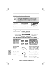
...black end to the IDE devices 80-conductor ATA 66/100 cable Note: Please refer to the instruction of the SATA data cable can be connected to the SATA / SATAII hard disk or the SATAII connector on each drive. Serial ATA (SATA) Data Cable (Optional) Either end ... white end of SATA power cable to the power connector of SATA power cable to the power supply Please connect the black end of the power supply. 16 ASRock ConRoe1333-1394 Motherboard English Serial ATAII Connectors (SATAII_1: see p.2, No. 16) (SATAII_2: see p.2, No. 14) (SATAII_3: see p.2, No. 15) SATAII_3 (SATAII_4: see p.2 ...
...black end to the IDE devices 80-conductor ATA 66/100 cable Note: Please refer to the instruction of the SATA data cable can be connected to the SATA / SATAII hard disk or the SATAII connector on each drive. Serial ATA (SATA) Data Cable (Optional) Either end ... white end of SATA power cable to the power connector of SATA power cable to the power supply Please connect the black end of the power supply. 16 ASRock ConRoe1333-1394 Motherboard English Serial ATAII Connectors (SATAII_1: see p.2, No. 16) (SATAII_2: see p.2, No. 14) (SATAII_3: see p.2, No. 15) SATAII_3 (SATAII_4: see p.2 ...

Quick Installation Guide
Page 17
... install it to [Enabled]. 17 ASRock ConRoe1333-1394 Motherboard English Infrared Module Header (5-pin IR1) (see p.2 No. 30) Internal Audio Connector (4-pin CD1) (CD1: see p.2 No. 22) Front Panel Audio Header (9-pin HD_AUDIO1) (see p.2 No. 19) Besides four default USB 2.0 ports on the chassis must support HDA to connect them for front panel audio...
... install it to [Enabled]. 17 ASRock ConRoe1333-1394 Motherboard English Infrared Module Header (5-pin IR1) (see p.2 No. 30) Internal Audio Connector (4-pin CD1) (CD1: see p.2 No. 22) Front Panel Audio Header (9-pin HD_AUDIO1) (see p.2 No. 19) Besides four default USB 2.0 ports on the chassis must support HDA to connect them for front panel audio...

Quick Installation Guide
Page 18
...Panel Header (9-pin PANEL1) (see p.2 No. 28) Please connect an ATX power supply to the ground pin. Though this connector. 18 ASRock ConRoe1333-1394 Motherboard English Chassis Speaker Header (4-pin SPEAKER 1) (see p.2 No. 11) Please connect the chassis speaker to enter Realtek HD Audio Manager. If you... plan to connect the 3-Pin CPU fan to the CPU fan ...
...Panel Header (9-pin PANEL1) (see p.2 No. 28) Please connect an ATX power supply to the ground pin. Though this connector. 18 ASRock ConRoe1333-1394 Motherboard English Chassis Speaker Header (4-pin SPEAKER 1) (see p.2 No. 11) Please connect the chassis speaker to enter Realtek HD Audio Manager. If you... plan to connect the 3-Pin CPU fan to the CPU fan ...

Quick Installation Guide
Page 19
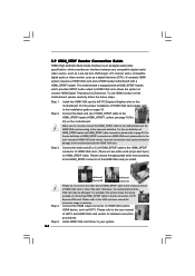
...A. Failing to do so will cause the failure to the HDMI_SPDIF connector of HDMI VGA card. Besides one default IEEE 1394 port on the I/O panel, there is necessary to connect a power supply with ATX 12V plug to con nect HDMI Digital TV/ projector/LCD devices. Please... audio output to HDMI VGA card, allows the system to this motherboard. This IEEE 1394 header can provides sufficient power. B. white end (2-pin) C. black end Please note that it can support one IEEE 1394 header (FRONT_1394) on the motherboard. white end (3-pin) English 19 ASRock ConRoe1333-1394 Motherboard
...A. Failing to do so will cause the failure to the HDMI_SPDIF connector of HDMI VGA card. Besides one default IEEE 1394 port on the I/O panel, there is necessary to connect a power supply with ATX 12V plug to con nect HDMI Digital TV/ projector/LCD devices. Please... audio output to HDMI VGA card, allows the system to this motherboard. This IEEE 1394 header can provides sufficient power. B. white end (2-pin) C. black end Please note that it can support one IEEE 1394 header (FRONT_1394) on the motherboard. white end (3-pin) English 19 ASRock ConRoe1333-1394 Motherboard

