User Manual
Page 7
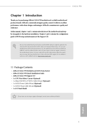
... specific information about the model you for purchasing ASRock C621A WS motherboard, a reliable motherboard produced under ASRock's consistently stringent quality control. Because the motherboard specifications and the BIOS software might be updated, the content of the motherboard and stepby-step guide to change without further notice. You may find the latest VGA cards and CPU support list on ASRock's website without notice. In this manual, chapter 1 and 2 contains introduction of this documentation occur, the updated version...
... specific information about the model you for purchasing ASRock C621A WS motherboard, a reliable motherboard produced under ASRock's consistently stringent quality control. Because the motherboard specifications and the BIOS software might be updated, the content of the motherboard and stepby-step guide to change without further notice. You may find the latest VGA cards and CPU support list on ASRock's website without notice. In this manual, chapter 1 and 2 contains introduction of this documentation occur, the updated version...
User Manual
Page 9
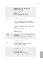
...Socket (M2_2, Key M), supports type 2242/2280/22110 SATA3 6.0 Gb/s & PCIe Gen3x1 (8 Gb/s) modes* * Supports Intel® OptaneTM Technology * Supports NVMe SSD as boot disks * Supports ASRock U.2 Ki RAID • Supports RAID 0, RAID 1, RAID 5 and RAID 10 for SATA storage devices • Supports RAID 0, RAID 1, RAID 5 for M.2 NVMe storage devices Rear Panel I/O • 1 x UID Switch w/ LED • 1 x D-Sub Port • 4 x USB 3.2 Gen1 Ports (Supports ESD Protection) • 2 x RJ45 (10GbE), 2 x RJ45 (1GbE) • 1 x RJ45 Dedicated IPMI LAN port Connector • 1 x SPI TPM Header...
...Socket (M2_2, Key M), supports type 2242/2280/22110 SATA3 6.0 Gb/s & PCIe Gen3x1 (8 Gb/s) modes* * Supports Intel® OptaneTM Technology * Supports NVMe SSD as boot disks * Supports ASRock U.2 Ki RAID • Supports RAID 0, RAID 1, RAID 5 and RAID 10 for SATA storage devices • Supports RAID 0, RAID 1, RAID 5 for M.2 NVMe storage devices Rear Panel I/O • 1 x UID Switch w/ LED • 1 x D-Sub Port • 4 x USB 3.2 Gen1 Ports (Supports ESD Protection) • 2 x RJ45 (10GbE), 2 x RJ45 (1GbE) • 1 x RJ45 Dedicated IPMI LAN port Connector • 1 x SPI TPM Header...

User Manual
Page 10
...CPU HP-SMBus Connector • 1 x Thermal Sensor Header • 1 x Virtual RAID On CPU Header • 1 x BMC Heartbeat LED • 1 x StandbyPower LED • 5 x FanFail LED • 1 x Non Maskable Interrupt Button Header • 1 x Buzzer • 1 x Dr. Debug with LED BIOS Feature • AMI UEFI Legal BIOS • ACPI 5.0 Compliant wake up events • SMBIOS 2.3 Support English Hardware Monitor • Temperature Sensing: CPU, PCH, MB, Card Side • Fan Tachometer: CPU, Rear, Front Fan Tachometer • Quiet Fan (Auto adjust chassis fan speed by CPU temperature): CPU...
...CPU HP-SMBus Connector • 1 x Thermal Sensor Header • 1 x Virtual RAID On CPU Header • 1 x BMC Heartbeat LED • 1 x StandbyPower LED • 5 x FanFail LED • 1 x Non Maskable Interrupt Button Header • 1 x Buzzer • 1 x Dr. Debug with LED BIOS Feature • AMI UEFI Legal BIOS • ACPI 5.0 Compliant wake up events • SMBIOS 2.3 Support English Hardware Monitor • Temperature Sensing: CPU, PCH, MB, Card Side • Fan Tachometer: CPU, Rear, Front Fan Tachometer • Quiet Fan (Auto adjust chassis fan speed by CPU temperature): CPU...

User Manual
Page 14
... USB 2.0 Port (USB_1) 35 Front LAN LED Header (FRONT_LED_LAN34) 36 TPM Header (TPM1) 37 SATA SGPIO Connector (SATA_SGPIO1) 38 SATA SGPIO Connector (SSATA_SGPIO1) 39 Thermal Sensor Header (TR1) 40 MiniSAS HD SATA/PCIE Slection Jumper (MINISAS_1) 41 BMC SMBus Header (BMC_SMB_1) 42 ESPI Flash Sharing Jumper (ESPI_SHARE) 43 Intelligent Platform Management Bus Header (IPMB1) 44 COM Header (COM1) 45 BIOS Recovery Jumper (BIOS_RECOVERY1) 46 Non Maskable Interrupt Button (NMI_BTN2) 47 PCI Express 4.0 x16 Card Slot (PCIE1) 48 CPU PECI Mode Jumper...
... USB 2.0 Port (USB_1) 35 Front LAN LED Header (FRONT_LED_LAN34) 36 TPM Header (TPM1) 37 SATA SGPIO Connector (SATA_SGPIO1) 38 SATA SGPIO Connector (SSATA_SGPIO1) 39 Thermal Sensor Header (TR1) 40 MiniSAS HD SATA/PCIE Slection Jumper (MINISAS_1) 41 BMC SMBus Header (BMC_SMB_1) 42 ESPI Flash Sharing Jumper (ESPI_SHARE) 43 Intelligent Platform Management Bus Header (IPMB1) 44 COM Header (COM1) 45 BIOS Recovery Jumper (BIOS_RECOVERY1) 46 Non Maskable Interrupt Button (NMI_BTN2) 47 PCI Express 4.0 x16 Card Slot (PCIE1) 48 CPU PECI Mode Jumper...

User Manual
Page 36
Please use a 20-pin ATX power 13 24 supply, please plug it along Pin 1 and Pin 13. This connector supports Trusted Platform Module (TPM) system, which can support two ports. 3V 12V 12V 5VSB PWROK_PS GND 5V GND 5V GND 3V 3V This motherboard provides a 24-pin ATX power connector. 1 12 To use a SATA power cable to connect this motherboard. A TPM system also helps enhance network security, protects digital identities, and ensures platform integrity. English...
Please use a 20-pin ATX power 13 24 supply, please plug it along Pin 1 and Pin 13. This connector supports Trusted Platform Module (TPM) system, which can support two ports. 3V 12V 12V 5VSB PWROK_PS GND 5V GND 5V GND 3V 3V This motherboard provides a 24-pin ATX power connector. 1 12 To use a SATA power cable to connect this motherboard. A TPM system also helps enhance network security, protects digital identities, and ensures platform integrity. English...

User Manual
Page 38
... p.6, No. 16) Serial Port Header (9-pin COM1) (see p.6, No. 44) Clear CMOS Pad (CLRMOS1) (see p.6, No. 58) Non Maskable Interrupt Button Header (NMI_BTN2) (see p.6, No. 46) SATA_5 SATA_4 The SATA3 DOM connectors support both SATA DOMs (Disk-On-Module) and SATA data cables for internal storage devices with up to 6.0 Gb/s data transfer rate. *2 Type-C USB headers (USB31_TC1/ USB31_TC2) are shared with 2 SATA 7-pin headers (SSATA_2/SSATA_3) (BOM option). This COM header supports a serial port module. English 32
... p.6, No. 16) Serial Port Header (9-pin COM1) (see p.6, No. 44) Clear CMOS Pad (CLRMOS1) (see p.6, No. 58) Non Maskable Interrupt Button Header (NMI_BTN2) (see p.6, No. 46) SATA_5 SATA_4 The SATA3 DOM connectors support both SATA DOMs (Disk-On-Module) and SATA data cables for internal storage devices with up to 6.0 Gb/s data transfer rate. *2 Type-C USB headers (USB31_TC1/ USB31_TC2) are shared with 2 SATA 7-pin headers (SSATA_2/SSATA_3) (BOM option). This COM header supports a serial port module. English 32

User Manual
Page 41
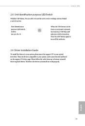
... can work properly. Press the UID button again to turn off the indicator. 2.9 Driver Installation Guide To install the drivers to your system, please insert the support CD to your optical drive first. Unit Identification purpose LED/Switch (UID1) (see p.11, No. 9) When the UID button on the front or rear panel is pressed, the front/rear UID blue LED indicator will be auto-detected and listed...
... can work properly. Press the UID button again to turn off the indicator. 2.9 Driver Installation Guide To install the drivers to your system, please insert the support CD to your optical drive first. Unit Identification purpose LED/Switch (UID1) (see p.11, No. 9) When the UID button on the front or rear panel is pressed, the front/rear UID blue LED indicator will be auto-detected and listed...

User Manual
Page 44
... match what you start up the default system device to locate and load the Operating System For event log configuration To exit the current screen or the UEFI SETUP UTILITY Use < > key or < > key to choose among the selections on the system chassis. Because the UEFI software is constantly being updated, the following selections: Item Main Advanced Server Mgmt Security Boot Event Logs Exit Description To set up the system...
... match what you start up the default system device to locate and load the Operating System For event log configuration To exit the current screen or the UEFI SETUP UTILITY Use < > key or < > key to choose among the selections on the system chassis. Because the UEFI software is constantly being updated, the following selections: Item Main Advanced Server Mgmt Security Boot Event Logs Exit Description To set up the system...

User Manual
Page 57
... select Function Key and Keypad on Putty. Putty Keypad Use this item to enable or disable extended terminal resolution support. Resolution On Legacy OS, the Number of a serial data packet. The options include [7] and [8] (Bits). C621A WS Bits Per Second Use this item to select the parity bit. Parity Use this item to select the serial port transmission speed. The standard setting is [1] Stop Bit. Legacy Console Redirection Legacy Console Redirection Settings Use this...
... select Function Key and Keypad on Putty. Putty Keypad Use this item to enable or disable extended terminal resolution support. Resolution On Legacy OS, the Number of a serial data packet. The options include [7] and [8] (Bits). C621A WS Bits Per Second Use this item to select the parity bit. Parity Use this item to select the serial port transmission speed. The standard setting is [1] Stop Bit. Legacy Console Redirection Legacy Console Redirection Settings Use this...

User Manual
Page 58
... connected exchange information. Flow Control Use this item is enabled for Console Redirection. Long or noisy lines may require lower transmission speed. It is disabled before booting to legacy OS. Console Redirection Settings Use this item to select the serial port transmission speed. If this item to set to Enabled, you are full, a "stop" signal can select a COM Port to be sent to stop signals. Redirect After POST...
... connected exchange information. Flow Control Use this item is enabled for Console Redirection. Long or noisy lines may require lower transmission speed. It is disabled before booting to legacy OS. Console Redirection Settings Use this item to select the serial port transmission speed. If this item to set to Enabled, you are full, a "stop" signal can select a COM Port to be sent to stop signals. Redirect After POST...

User Manual
Page 59
C621A WS 3.3.8 H/W Monitor In this section, it allows you to enable or disable the Watch Dog Timer. Watch Dog Timer This allows you to monitor the status of the hardware on your system, including the parameters of the CPU temperature, motherboard temperature, CPU fan speed, chassis fan speed, and the critical voltage. Fan Control If [Auto] is [Smart Fan]. FAN 1 This allows you to set the fan 3's speed. The default value is selected, the fan speed will controlled by BMC. FAN 3 This...
C621A WS 3.3.8 H/W Monitor In this section, it allows you to enable or disable the Watch Dog Timer. Watch Dog Timer This allows you to monitor the status of the hardware on your system, including the parameters of the CPU temperature, motherboard temperature, CPU fan speed, chassis fan speed, and the critical voltage. Fan Control If [Auto] is [Smart Fan]. FAN 1 This allows you to set the fan 3's speed. The default value is selected, the fan speed will controlled by BMC. FAN 3 This...

User Manual
Page 70
... press enter to remove the password. Secure Boot Use this section, you may set or change the supervisor/user password for the system. Secure Boot Mode Secure Boot mode selector: Standard/Custom. Enable to change the settings in the UEFI Setup Utility. Users are unable to change the settings in the UEFI Setup Utility. Supervisor Password Set or change the password for the user account. The default value is [Disabled]. User Password Set or change the password for the administrator account. 3.5 Security In this to enable or disable Secure Boot Control...
... press enter to remove the password. Secure Boot Use this section, you may set or change the supervisor/user password for the system. Secure Boot Mode Secure Boot mode selector: Standard/Custom. Enable to change the settings in the UEFI Setup Utility. Users are unable to change the settings in the UEFI Setup Utility. Supervisor Password Set or change the password for the user account. The default value is [Disabled]. User Password Set or change the password for the administrator account. 3.5 Security In this to enable or disable Secure Boot Control...

User Manual
Page 81
... only. C621A WS Chapter 4 Software Support 4.1 Install Operating System This motherboard supports various Microsoft® Windows® Server 2012 R2 / Linux compliant. Refer to activate the devices. 4.2.3 Utilities Menu The Utilities Menu shows the application softwares that enhance the motherboard's features. 4.2.1 Running The Support CD To begin using the support CD, insert the CD into your CD-ROM drive. Because motherboard settings and hardware options vary, use the setup procedures in the Support CD to install it...
... only. C621A WS Chapter 4 Software Support 4.1 Install Operating System This motherboard supports various Microsoft® Windows® Server 2012 R2 / Linux compliant. Refer to activate the devices. 4.2.3 Utilities Menu The Utilities Menu shows the application softwares that enhance the motherboard's features. 4.2.1 Running The Support CD To begin using the support CD, insert the CD into your CD-ROM drive. Because motherboard settings and hardware options vary, use the setup procedures in the Support CD to install it...

Quick Installation Guide
Page 5
... USB 2.0 Port (USB_1) 35 Front LAN LED Header (FRONT_LED_LAN34) 36 TPM Header (TPM1) 37 SATA SGPIO Connector (SATA_SGPIO1) 38 SATA SGPIO Connector (SSATA_SGPIO1) 39 Thermal Sensor Header (TR1) 40 MiniSAS HD SATA/PCIE Slection Jumper (MINISAS_1) 41 BMC SMBus Header (BMC_SMB_1) 42 ESPI Flash Sharing Jumper (ESPI_SHARE) 43 Intelligent Platform Management Bus Header (IPMB1) 44 COM Header (COM1) 45 BIOS Recovery Jumper (BIOS_RECOVERY1) 46 Non Maskable Interrupt Button (NMI_BTN2) 47 PCI Express 4.0 x16 Card Slot (PCIE1) 48 CPU PECI Mode Jumper...
... USB 2.0 Port (USB_1) 35 Front LAN LED Header (FRONT_LED_LAN34) 36 TPM Header (TPM1) 37 SATA SGPIO Connector (SATA_SGPIO1) 38 SATA SGPIO Connector (SSATA_SGPIO1) 39 Thermal Sensor Header (TR1) 40 MiniSAS HD SATA/PCIE Slection Jumper (MINISAS_1) 41 BMC SMBus Header (BMC_SMB_1) 42 ESPI Flash Sharing Jumper (ESPI_SHARE) 43 Intelligent Platform Management Bus Header (IPMB1) 44 COM Header (COM1) 45 BIOS Recovery Jumper (BIOS_RECOVERY1) 46 Non Maskable Interrupt Button (NMI_BTN2) 47 PCI Express 4.0 x16 Card Slot (PCIE1) 48 CPU PECI Mode Jumper...

Quick Installation Guide
Page 14
...CPU HP-SMBus Connector • 1 x Thermal Sensor Header • 1 x Virtual RAID On CPU Header • 1 x BMC Heartbeat LED • 1 x StandbyPower LED • 5 x FanFail LED • 1 x Non Maskable Interrupt Button Header • 1 x Buzzer • 1 x Dr. Debug with LED BIOS Feature • AMI UEFI Legal BIOS • ACPI 5.0 Compliant wake up events • SMBIOS 2.3 Support English Hardware Monitor • Temperature Sensing: CPU, PCH, MB, Card Side • Fan Tachometer: CPU, Rear, Front Fan Tachometer • Quiet Fan (Auto adjust chassis fan speed by CPU temperature): CPU...
...CPU HP-SMBus Connector • 1 x Thermal Sensor Header • 1 x Virtual RAID On CPU Header • 1 x BMC Heartbeat LED • 1 x StandbyPower LED • 5 x FanFail LED • 1 x Non Maskable Interrupt Button Header • 1 x Buzzer • 1 x Dr. Debug with LED BIOS Feature • AMI UEFI Legal BIOS • ACPI 5.0 Compliant wake up events • SMBIOS 2.3 Support English Hardware Monitor • Temperature Sensing: CPU, PCH, MB, Card Side • Fan Tachometer: CPU, Rear, Front Fan Tachometer • Quiet Fan (Auto adjust chassis fan speed by CPU temperature): CPU...

Quick Installation Guide
Page 32
This connector supports Trusted Platform Module (TPM) system, which can support two ports. 3V 12V 12V 5VSB PWROK_PS GND 5V GND 5V GND 3V 3V This motherboard provides a 24-pin ATX power connector. 1 12 To use a SATA power cable to connect this motherboard. A TPM system also helps enhance network security, protects digital identities, and ensures platform integrity. English Please use a 20-pin ATX power 13 24 supply, please plug it along Pin 1 and Pin 13...
This connector supports Trusted Platform Module (TPM) system, which can support two ports. 3V 12V 12V 5VSB PWROK_PS GND 5V GND 5V GND 3V 3V This motherboard provides a 24-pin ATX power connector. 1 12 To use a SATA power cable to connect this motherboard. A TPM system also helps enhance network security, protects digital identities, and ensures platform integrity. English Please use a 20-pin ATX power 13 24 supply, please plug it along Pin 1 and Pin 13...
Quick Installation Guide
Page 37
... LED/Switch (UID1) (see p.6, No. 9) When the UID button on the front or rear panel is pressed, the front/rear UID blue LED indicator will be auto-detected and listed on from top to bottom to install those required drivers. Then, the drivers compatible to your optical drive first. C621A WS 2.8 Unit Identification purpose LED/Switch With the UID button, You are able to locate the server you install...
... LED/Switch (UID1) (see p.6, No. 9) When the UID button on the front or rear panel is pressed, the front/rear UID blue LED indicator will be auto-detected and listed on from top to bottom to install those required drivers. Then, the drivers compatible to your optical drive first. C621A WS 2.8 Unit Identification purpose LED/Switch With the UID button, You are able to locate the server you install...

Quick Installation Guide
Page 204
... pin 12V 1 x 直式 A USB 2.0 •• 1 x USB 2.0 2 個 USB 2.0 1 x USB 3.2 Gen1 2 個 USB 3.2 Gen1 2 x USB3.2 Gen2 2 Type-C 2 x 前面板 Type C USB 3.2 Gen2 2 x SGPIO 1 x 1 x Intelligent Platform Management Bus 1 x 背板 PCI Express 1 x SMBus 1 x PMbus 1 x CPU HP-SMBus 1 x 1 x Virtual RAID On CPU 1 x BMC 心跳 LED •• 1 x LED •• 5 x LED •• 1 x Non Maskable Interrupt 1 x 1 x Dr. Debug,含 LED •• AMI UEFI Legal BIOS •• ACPI 5.0 SMBIOS...
... pin 12V 1 x 直式 A USB 2.0 •• 1 x USB 2.0 2 個 USB 2.0 1 x USB 3.2 Gen1 2 個 USB 3.2 Gen1 2 x USB3.2 Gen2 2 Type-C 2 x 前面板 Type C USB 3.2 Gen2 2 x SGPIO 1 x 1 x Intelligent Platform Management Bus 1 x 背板 PCI Express 1 x SMBus 1 x PMbus 1 x CPU HP-SMBus 1 x 1 x Virtual RAID On CPU 1 x BMC 心跳 LED •• 1 x LED •• 5 x LED •• 1 x Non Maskable Interrupt 1 x 1 x Dr. Debug,含 LED •• AMI UEFI Legal BIOS •• ACPI 5.0 SMBIOS...
Intel Rapid Storage Guide
Page 13
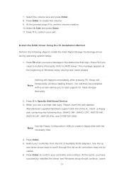
... list of Windows setup (during operating system setup: 1. At the prompt press Y to Specify Additional Device. 3. You will then be visible. 6. Use the Floppy Configuration Utility to confirm your controller and continue. Leave 13 Select 4: Exit and press Enter. 11. At this point, you to install a third party SCSI or RAID driver. Select the volume size and press Enter. 8. Press Enter to install the Intel Rapid Storage Technology driver during text-mode...
... list of Windows setup (during operating system setup: 1. At the prompt press Y to Specify Additional Device. 3. You will then be visible. 6. Use the Floppy Configuration Utility to confirm your controller and continue. Leave 13 Select 4: Exit and press Enter. 11. At this point, you to install a third party SCSI or RAID driver. Select the volume size and press Enter. 8. Press Enter to install the Intel Rapid Storage Technology driver during text-mode...

Intel Rapid Storage Guide
Page 16
... in RAID mode or AHCI mode, the F6 installation method must be prompted with the necessary files. You can use a USB floppy drive or create a slipstream version of the operating system. 16 Nothing will Note temporarily continue loading drivers. You will then be used to load support for mass storage device(s). 2. How to load the driver during OS installation using the F6 installation method. 1. Press S to install the Intel® Rapid Storage Technology driver using F6 when in AHCI/RAID mode...
... in RAID mode or AHCI mode, the F6 installation method must be prompted with the necessary files. You can use a USB floppy drive or create a slipstream version of the operating system. 16 Nothing will Note temporarily continue loading drivers. You will then be used to load support for mass storage device(s). 2. How to load the driver during OS installation using the F6 installation method. 1. Press S to install the Intel® Rapid Storage Technology driver using F6 when in AHCI/RAID mode...


