
User Manual
Page 6
... ECC memory is only supported with processors which are GPU integrated. - Supports Intel® 32 nm CPU - Intel® Socket 1155 for 3rd/2nd Generation CoreTM i7/CoreTM i5/ CoreTM i3 Processors - Max. Supports AMD Quad CrossFireXTM, 3-Way CrossFireXTM and CrossFireXTM...24.4 cm - 1.2 Specifications Platform CPU Chipset Memory Expansion Slot Graphics - Intel® Socket 1155 for Intel® E3-1200/12x5 v2 processors - Digi Power Design - 8 + 4 Power Phase Design - Intel® C216 - Premium Gold Capacitor design (100% Japan-made high-quality Conductive Polymer Capacitors) -...
... ECC memory is only supported with processors which are GPU integrated. - Supports Intel® 32 nm CPU - Intel® Socket 1155 for 3rd/2nd Generation CoreTM i7/CoreTM i5/ CoreTM i3 Processors - Max. Supports AMD Quad CrossFireXTM, 3-Way CrossFireXTM and CrossFireXTM...24.4 cm - 1.2 Specifications Platform CPU Chipset Memory Expansion Slot Graphics - Intel® Socket 1155 for Intel® E3-1200/12x5 v2 processors - Digi Power Design - 8 + 4 Power Phase Design - Intel® C216 - Premium Gold Capacitor design (100% Japan-made high-quality Conductive Polymer Capacitors) -...

User Manual
Page 11
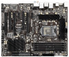
... 30 29 28 RoHS HD_AUDIO1 1 HDMI_SPDIF1 COM1 1 1 PCI2 C216 WS PCIE5 IR1 1 FRONT_1394 1 CLRCMOS1 1 CHA_FAN1 USB8_9 1 USB6_7 1 Dr. Debug 64Mb BIOS SPEAKER1 1 PLED1 1 PLED PWRBTN CHA_FAN3 1 HDLED RESET PANEL1 15 27 26 25 24 23 22 21 20 19 18 17 16 1 1155-Pin CPU Socket 2 ATX 12V Power Connector (ATX12V1) 3 CPU Fan Connector...
... 30 29 28 RoHS HD_AUDIO1 1 HDMI_SPDIF1 COM1 1 1 PCI2 C216 WS PCIE5 IR1 1 FRONT_1394 1 CLRCMOS1 1 CHA_FAN1 USB8_9 1 USB6_7 1 Dr. Debug 64Mb BIOS SPEAKER1 1 PLED1 1 PLED PWRBTN CHA_FAN3 1 HDLED RESET PANEL1 15 27 26 25 24 23 22 21 20 19 18 17 16 1 1155-Pin CPU Socket 2 ATX 12V Power Connector (ATX12V1) 3 CPU Fan Connector...

User Manual
Page 16
2.3 CPU Installation In order to provide the LGA 1155 CPU sockets more protection and make the installation process easier, ASRock has added a new protection cover on top of Intel® 1155-Pin CPUs with the new protection cover, please follow the steps below. black line Step 2. For the installation... 1-1. Disengage the lever by the edge which is found. Load Plate Cover Load Lever Contact Array Socket Body 1155-Pin Socket Overview Before you insert the 1155-Pin CPU into the socket if above situation is marked with the IHS (Integrated Heat Sink) up the load plate. Keep the...
2.3 CPU Installation In order to provide the LGA 1155 CPU sockets more protection and make the installation process easier, ASRock has added a new protection cover on top of Intel® 1155-Pin CPUs with the new protection cover, please follow the steps below. black line Step 2. For the installation... 1-1. Disengage the lever by the edge which is found. Load Plate Cover Load Lever Contact Array Socket Body 1155-Pin Socket Overview Before you insert the 1155-Pin CPU into the socket if above situation is marked with the IHS (Integrated Heat Sink) up the load plate. Keep the...

User Manual
Page 17
... 3-2. Press down the load lever, and secure it with the two alignment keys of the socket. orientation key notch Pin1 alignment key orientation key notch 1155-Pin CPU alignment key 1155-Pin Socket Pin1 For proper installation, please ensure to match the two orientation key notches of the CPU with...itself. Step 3. The cover must be placed if you wish to the orient keys. Close the socket: Step 3-1. Please save and replace the cover if the processor is within the socket and properly mated to return the motherboard for after service. 17 Carefully place the CPU into the...
... 3-2. Press down the load lever, and secure it with the two alignment keys of the socket. orientation key notch Pin1 alignment key orientation key notch 1155-Pin CPU alignment key 1155-Pin Socket Pin1 For proper installation, please ensure to match the two orientation key notches of the CPU with...itself. Step 3. The cover must be placed if you wish to the orient keys. Close the socket: Step 3-1. Please save and replace the cover if the processor is within the socket and properly mated to return the motherboard for after service. 17 Carefully place the CPU into the...

User Manual
Page 18
...Installation of CPU Fan and Heatsink This motherboard is an example to illustrate the installation of the heatsink for Socket LGA 1155/1156 CPU fan. 18 Ensure that supports Intel 1155-Pin CPUs. Step 6. No.4). Rotate the fastener clockwise, then press down the fasteners without rotating them ...and the heatsink are for 1155-Pin CPUs. Ensure that this motherboard supports Combo Cooler Option (C.C.O.), which provides flexible options to adopt three different CPU cooler types, Socket LGA 775, LGA 1155 and LGA 1156. Place the heatsink onto the socket. Please adopt the type of...
...Installation of CPU Fan and Heatsink This motherboard is an example to illustrate the installation of the heatsink for Socket LGA 1155/1156 CPU fan. 18 Ensure that supports Intel 1155-Pin CPUs. Step 6. No.4). Rotate the fastener clockwise, then press down the fasteners without rotating them ...and the heatsink are for 1155-Pin CPUs. Ensure that this motherboard supports Combo Cooler Option (C.C.O.), which provides flexible options to adopt three different CPU cooler types, Socket LGA 775, LGA 1155 and LGA 1156. Place the heatsink onto the socket. Please adopt the type of...