
User Manual
Page 4
... 2 1.3 Motherboard Layout 6 1.4 I/O Panel 8 Chapter 2 Installation 10 2.1 Installing the CPU 11 2.2 Installing the CPU Fan and Heatsink 14 2.3 Installing Memory Modules (DIMM) 15 2.4 Expansion Slots (PCI Express Slots) 17 2.5 Jumpers Setup 18 2.6 Onboard Headers and Connectors 19 Chapter 3 Software and Utilities Operation 23 3.1 Installing Drivers 23 3.2 A-Tuning 24 3.3 Intel® Rapid Start Technology 30 3.4 Intel® Smart Connect Technology 35 3.5 ASRock Cloud 40 3.6 ASRock APP Shop 50 3.6.1 UI Overview 50 3.6.2 Apps 51 3.6.3 BIOS & Drivers 54
... 2 1.3 Motherboard Layout 6 1.4 I/O Panel 8 Chapter 2 Installation 10 2.1 Installing the CPU 11 2.2 Installing the CPU Fan and Heatsink 14 2.3 Installing Memory Modules (DIMM) 15 2.4 Expansion Slots (PCI Express Slots) 17 2.5 Jumpers Setup 18 2.6 Onboard Headers and Connectors 19 Chapter 3 Software and Utilities Operation 23 3.1 Installing Drivers 23 3.2 A-Tuning 24 3.3 Intel® Rapid Start Technology 30 3.4 Intel® Smart Connect Technology 35 3.5 ASRock Cloud 40 3.6 ASRock APP Shop 50 3.6.1 UI Overview 50 3.6.2 Apps 51 3.6.3 BIOS & Drivers 54
User Manual
Page 6
...; ASRock B85 Anniversary Motherboard (ATX Form Factor) • ASRock B85 Anniversary Quick Installation Guide • ASRock B85 Anniversary Support CD • 2 x Serial ATA (SATA) Data Cables (Optional) • 1 x I/O Panel Shield 1 English Chapter 3 contains the operation guide of this manual, Chapter 1 and 2 contains the introduction of the BIOS setup. Because the motherboard speciications and the BIOS sotware might be updated, the content of this motherboard, please visit our website for speciic information about the model you for purchasing ASRock B85 Anniversary motherboard...
...; ASRock B85 Anniversary Motherboard (ATX Form Factor) • ASRock B85 Anniversary Quick Installation Guide • ASRock B85 Anniversary Support CD • 2 x Serial ATA (SATA) Data Cables (Optional) • 1 x I/O Panel Shield 1 English Chapter 3 contains the operation guide of this manual, Chapter 1 and 2 contains the introduction of the BIOS setup. Because the motherboard speciications and the BIOS sotware might be updated, the content of this motherboard, please visit our website for speciic information about the model you for purchasing ASRock B85 Anniversary motherboard...
User Manual
Page 9
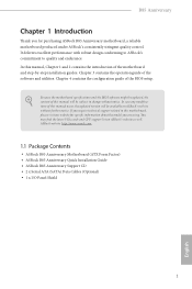
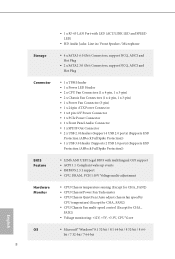
...; 1 x 8 pin 12V Power Connector • 1 x PCIe Power Connector • 1 x Front Panel Audio Connector • 1 x SPDIF Out Connector • 2 x USB 2.0 Headers (Support 4 USB 2.0 ports) (Supports ESD Protection (ASRock Full Spike Protection)) • 1 x USB 3.0 Header (Supports 2 USB 3.0 ports) (Supports ESD Protection (ASRock Full Spike Protection)) BIOS Feature • 32Mb AMI UEFI Legal BIOS with multilingual GUI support • ACPI 1.1 Compliant wake up events • SMBIOS 2.3.1 support • CPU, DRAM, PCH 1.05V Voltage multi-adjustment Hardware Monitor • CPU/Chassis...
...; 1 x 8 pin 12V Power Connector • 1 x PCIe Power Connector • 1 x Front Panel Audio Connector • 1 x SPDIF Out Connector • 2 x USB 2.0 Headers (Support 4 USB 2.0 ports) (Supports ESD Protection (ASRock Full Spike Protection)) • 1 x USB 3.0 Header (Supports 2 USB 3.0 ports) (Supports ESD Protection (ASRock Full Spike Protection)) BIOS Feature • 32Mb AMI UEFI Legal BIOS with multilingual GUI support • ACPI 1.1 Compliant wake up events • SMBIOS 2.3.1 support • CPU, DRAM, PCH 1.05V Voltage multi-adjustment Hardware Monitor • CPU/Chassis...

User Manual
Page 12
... (SATA_1) 9 SATA3 Connector (SATA_0) 10 SATA3 Connector (SATA_3) 11 SATA3 Connector (SATA_2) 12 SATA2 Connector (SATA_5) 13 SATA2 Connector (SATA3_4) 14 Chassis Fan Connector (CHA_FAN1) 15 System Panel Header (PANEL1) 16 Power LED Header (PLED1) 17 USB 2.0 Header (USB_8_9) 18 USB 2.0 Header (USB_6_7) 19 TPM Header (TPMS1) 20 Chassis Speaker Header (SPEAKER1) 21 Clear CMOS Jumper (CLRCMOS1) 22 SPDIF Out Connector (SPDIF_OUT1) 23 Front Panel Audio Header (HD_AUDIO1) 24 CPU Fan Connector (CPU_FAN1) 25 PCIe Power Connector (PCIE_PWR1) 26 CPU Fan Connector (CPU_FAN2) B85 Anniversary English 7 No...
... (SATA_1) 9 SATA3 Connector (SATA_0) 10 SATA3 Connector (SATA_3) 11 SATA3 Connector (SATA_2) 12 SATA2 Connector (SATA_5) 13 SATA2 Connector (SATA3_4) 14 Chassis Fan Connector (CHA_FAN1) 15 System Panel Header (PANEL1) 16 Power LED Header (PLED1) 17 USB 2.0 Header (USB_8_9) 18 USB 2.0 Header (USB_6_7) 19 TPM Header (TPMS1) 20 Chassis Speaker Header (SPEAKER1) 21 Clear CMOS Jumper (CLRCMOS1) 22 SPDIF Out Connector (SPDIF_OUT1) 23 Front Panel Audio Header (HD_AUDIO1) 24 CPU Fan Connector (CPU_FAN1) 25 PCIe Power Connector (PCIE_PWR1) 26 CPU Fan Connector (CPU_FAN2) B85 Anniversary English 7 No...

User Manual
Page 22
... used for PCI Express x1 lane width cards. PCIE3 (PCIe 2.0 x1 slot) is used for PCI Express x1 lane width cards. Please read the documentation of the expansion card and make sure that the power supply is switched of or the power cord is used for PCI Express x16 lane width graphics cards. B85 Anniversary 2.4 Expansion Slots (PCI Express Slots) here are 6 PCI Express slots on the motherboard. PCIE4 (PCIe 2.0 x1 slot) is unplugged. Before installing an expansion card, please make necessary hardware settings for PCI Express...
... used for PCI Express x1 lane width cards. PCIE3 (PCIe 2.0 x1 slot) is used for PCI Express x1 lane width cards. Please read the documentation of the expansion card and make sure that the power supply is switched of or the power cord is used for PCI Express x16 lane width graphics cards. B85 Anniversary 2.4 Expansion Slots (PCI Express Slots) here are 6 PCI Express slots on the motherboard. PCIE4 (PCIe 2.0 x1 slot) is unplugged. Before installing an expansion card, please make necessary hardware settings for PCI Express...

User Manual
Page 23
... down before you update the BIOS. To clear and reset the system parameters to clear the data in CMOS. Ater waiting for 5 seconds. Clear CMOS Jumper (CLRCMOS1) (see p.6, No. 21) Default Clear CMOS CLRCMOS1 allows you to default setup, please turn of the computer and unplug the power cord from the power supply. Please be noted that the password, date, time, and user default proile will be cleared only if the CMOS battery is "Short".
... down before you update the BIOS. To clear and reset the system parameters to clear the data in CMOS. Ater waiting for 5 seconds. Clear CMOS Jumper (CLRCMOS1) (see p.6, No. 21) Default Clear CMOS CLRCMOS1 allows you to default setup, please turn of the computer and unplug the power cord from the power supply. Please be noted that the password, date, time, and user default proile will be cleared only if the CMOS battery is "Short".

User Manual
Page 24
... hard drive is in S1/S3 sleep state. Press the reset switch to restart the computer if the computer freezes and fails to the motherboard. A front panel module mainly consists of when the system is reading or writing data. PWRBTN (Power Switch): Connect to indicate the system's power status. 19 he LED is of power switch, reset switch, power LED, hard drive activity LED, speaker and etc. Placing jumper caps over these headers and connectors. B85 Anniversary 2.6 Onboard Headers and Connectors Onboard headers...
... hard drive is in S1/S3 sleep state. Press the reset switch to restart the computer if the computer freezes and fails to the motherboard. A front panel module mainly consists of when the system is reading or writing data. PWRBTN (Power Switch): Connect to indicate the system's power status. 19 he LED is of power switch, reset switch, power LED, hard drive activity LED, speaker and etc. Placing jumper caps over these headers and connectors. B85 Anniversary 2.6 Onboard Headers and Connectors Onboard headers...

User Manual
Page 26
... 21 High Deinition Audio supports Jack Sensing, but the panel wire on the chassis must support HDA to install your system. 2. Please follow the instructions in the Realtek Control panel and adjust "Recording Volume". B85 Anniversary 1. Connect Ground (GND) to the ground pin. Chassis and Power Fan Connectors (4-pin CHA_FAN1) (see p.6, No. 14) (3-pin CHA_FAN2) (see p.6, No. 7) (3-pin PWR_FAN1) (see p.6, No. 26) GND +12V CPU_FAN_SPEED FAN_SPEED_CONTROL GND FAN_VOLTAGE FAN_SPEED his motherboard provides a 4-Pin CPU fan (Quiet Fan) connector...
... 21 High Deinition Audio supports Jack Sensing, but the panel wire on the chassis must support HDA to install your system. 2. Please follow the instructions in the Realtek Control panel and adjust "Recording Volume". B85 Anniversary 1. Connect Ground (GND) to the ground pin. Chassis and Power Fan Connectors (4-pin CHA_FAN1) (see p.6, No. 14) (3-pin CHA_FAN2) (see p.6, No. 7) (3-pin PWR_FAN1) (see p.6, No. 26) GND +12V CPU_FAN_SPEED FAN_SPEED_CONTROL GND FAN_VOLTAGE FAN_SPEED his motherboard provides a 4-Pin CPU fan (Quiet Fan) connector...

User Manual
Page 27
... LAD2 LAD1 GND S_PWRDWN# SERIRQ# GND his connector supports Trusted Platform Module (TPM) system, which can securely store keys, digital certiicates, passwords, and data. English 22 Please connect a 4 pin molex power cable to this connector when more than three graphics cards are installed. To use a 4-pin ATX power supply, please plug it along Pin 1 and Pin 5. To use a 20-pin ATX power supply, please plug it along Pin 1 and Pin 13. his motherboard provides a 24-pin ATX power connector. his motherboard provides an 8-pin ATX 12V power connector.
... LAD2 LAD1 GND S_PWRDWN# SERIRQ# GND his connector supports Trusted Platform Module (TPM) system, which can securely store keys, digital certiicates, passwords, and data. English 22 Please connect a 4 pin molex power cable to this connector when more than three graphics cards are installed. To use a 4-pin ATX power supply, please plug it along Pin 1 and Pin 5. To use a 20-pin ATX power supply, please plug it along Pin 1 and Pin 13. his motherboard provides a 24-pin ATX power connector. his motherboard provides an 8-pin ATX 12V power connector.
User Manual
Page 28
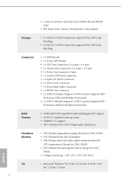
.... B85 Anniversary Chapter 3 Software and Utilities Operation 3.1 Installing Drivers he Utilities Menu shows the application sotware that enhance the motherboard's features. Running The Support CD To begin using the support CD, insert the CD into your system will be auto-detected and listed on the support CD driver page. Utilities Menu he Support CD that comes with the motherboard contains necessary drivers and useful utilities that the motherboard supports. If the Main Menu does not appear automatically, locate...
.... B85 Anniversary Chapter 3 Software and Utilities Operation 3.1 Installing Drivers he Utilities Menu shows the application sotware that enhance the motherboard's features. Running The Support CD To begin using the support CD, insert the CD into your system will be auto-detected and listed on the support CD driver page. Utilities Menu he Support CD that comes with the motherboard contains necessary drivers and useful utilities that the motherboard supports. If the Main Menu does not appear automatically, locate...

User Manual
Page 35
...; Rapid Start Technology Intel® Rapid Start Technology enables your system is already installed under IDE mode, directly changing the SATA mode to AHCI may cause Windows 8.1/8/7 to crash while booting. Feel secure to know that your motherboard supports this feature. • Operating system: Microsot Windows 8.1/8/7 (32- Please backup any important data before operating to AHCI. Double click on OK. 30 English If Windows 8.1/8/7 is not in Windows 8.1/8/7, type "Regedit" into...
...; Rapid Start Technology Intel® Rapid Start Technology enables your system is already installed under IDE mode, directly changing the SATA mode to AHCI may cause Windows 8.1/8/7 to crash while booting. Feel secure to know that your motherboard supports this feature. • Operating system: Microsot Windows 8.1/8/7 (32- Please backup any important data before operating to AHCI. Double click on OK. 30 English If Windows 8.1/8/7 is not in Windows 8.1/8/7, type "Regedit" into...

User Manual
Page 40
Press Win + R simultaneously in Windows 8/7, type "Regedit" into HKEY_LOCAL_MACHINE\SYSTEM\CurrentControlSet\services\ msahci in AHCI mode, please follow the instructions below. B85 Anniversary 3.4 Intel® Smart Connect Technology Intel® Smart Connect Technology is not in Windows Registry Editor. or 64-bit edition) • Set the SATA mode to avoid loss. 1. If your system is a feature that periodically wakes your motherboard supports this feature. • Operating system: Microsot Windows 8.1/8/7 (32- here are certain risks. Double...
Press Win + R simultaneously in Windows 8/7, type "Regedit" into HKEY_LOCAL_MACHINE\SYSTEM\CurrentControlSet\services\ msahci in AHCI mode, please follow the instructions below. B85 Anniversary 3.4 Intel® Smart Connect Technology Intel® Smart Connect Technology is not in Windows Registry Editor. or 64-bit edition) • Set the SATA mode to avoid loss. 1. If your system is a feature that periodically wakes your motherboard supports this feature. • Operating system: Microsot Windows 8.1/8/7 (32- here are certain risks. Double...

User Manual
Page 64
... make BIOS setup less diicult but also a lot more amusing. B85 Anniversary Chapter 4 UEFI SETUP UTILITY 4.1 Introduction ASRock Interactive UEFI is constantly being updated, the following selections: Main For setting system time/date information OC Tweaker For overclocking conigurations Advanced For advanced system conigurations Tool Useful tools H/W Monitor Displays current hardware status Boot For coniguring boot settings and boot priority Security For security settings Exit Exit the current screen or the UEFI Setup Utility 59...
... make BIOS setup less diicult but also a lot more amusing. B85 Anniversary Chapter 4 UEFI SETUP UTILITY 4.1 Introduction ASRock Interactive UEFI is constantly being updated, the following selections: Main For setting system time/date information OC Tweaker For overclocking conigurations Advanced For advanced system conigurations Tool Useful tools H/W Monitor Displays current hardware status Boot For coniguring boot settings and boot priority Security For security settings Exit Exit the current screen or the UEFI Setup Utility 59...

User Manual
Page 79
... controller. It will remain of the Power and Keyboard LEDs when the system enters into Standby/Hibernation mode. 74 English If [Power On] is on AC/Power Loss Select the power state ater a power failure. Onboard HDMI HD Audio Enable audio for power saving when the computer is shut down. Deep Sleep Conigure deep sleep mode for the onboard digital outputs. If [Power Of] is installed. Front Panel Enable/disable front panel HD audio. Onboard HD Audio Enable/disable onboard HD audio. Set to Auto to boot...
... controller. It will remain of the Power and Keyboard LEDs when the system enters into Standby/Hibernation mode. 74 English If [Power On] is on AC/Power Loss Select the power state ater a power failure. Onboard HDMI HD Audio Enable audio for power saving when the computer is shut down. Deep Sleep Conigure deep sleep mode for the onboard digital outputs. If [Power Of] is installed. Front Panel Enable/disable front panel HD audio. Onboard HD Audio Enable/disable onboard HD audio. Set to Auto to boot...

User Manual
Page 85
Select UEFI Setup Only to use USB devices under Windows® 7). Intel USB 3.0 Mode Select Intel® USB 3.0 controller mode. Set [Enabled] to keep the USB 3.0 driver enabled ater rebooting (USB 3.0 is enabled in BIOS). Set [Disabled] to keep the USB 3.0 driver enabled (Must install driver to support USB devices under the UEFI setup and Windows/Linux operating systems only. 80 English Set [Smart Auto] to disable the USB 3.0 ports. If you encounter USB compatibility issues it is disabled in BIOS). Select UEFI Setup Only to disable legacy USB support. If you...
Select UEFI Setup Only to use USB devices under Windows® 7). Intel USB 3.0 Mode Select Intel® USB 3.0 controller mode. Set [Enabled] to keep the USB 3.0 driver enabled ater rebooting (USB 3.0 is enabled in BIOS). Set [Disabled] to keep the USB 3.0 driver enabled (Must install driver to support USB devices under the UEFI setup and Windows/Linux operating systems only. 80 English Set [Smart Auto] to disable the USB 3.0 ports. If you encounter USB compatibility issues it is disabled in BIOS). Select UEFI Setup Only to disable legacy USB support. If you...

User Manual
Page 88
... internet connection settings for you are having trouble with your UEFI. Instant Flash Save UEFI iles in your system via an USB storage device, then downloads and installs the other required drivers automatically. Easy Driver Installer For users that installs the LAN driver to your USB pen drive before using this to install the drivers from our servers for Internet Flash. 83 English Network Coniguration Use this function. Please setup network coniguration before using UEFI Tech Service. 4.5 Tools B85 Anniversary UEFI Tech Service Contact ASRock Tech Service...
... internet connection settings for you are having trouble with your UEFI. Instant Flash Save UEFI iles in your system via an USB storage device, then downloads and installs the other required drivers automatically. Easy Driver Installer For users that installs the LAN driver to your USB pen drive before using this to install the drivers from our servers for Internet Flash. 83 English Network Coniguration Use this function. Please setup network coniguration before using UEFI Tech Service. 4.5 Tools B85 Anniversary UEFI Tech Service Contact ASRock Tech Service...

Quick Installation Guide
Page 4
... 7 Chassis Fan Connector (CHA_FAN2) 8 SATA3 Connector (SATA_1) 9 SATA3 Connector (SATA_0) 10 SATA3 Connector (SATA_3) 11 SATA3 Connector (SATA_2) 12 SATA2 Connector (SATA_5) 13 SATA2 Connector (SATA3_4) 14 Chassis Fan Connector (CHA_FAN1) 15 System Panel Header (PANEL1) 16 Power LED Header (PLED1) 17 USB 2.0 Header (USB_8_9) 18 USB 2.0 Header (USB_6_7) 19 TPM Header (TPMS1) 20 Chassis Speaker Header (SPEAKER1) 21 Clear CMOS Jumper (CLRCMOS1) 22 SPDIF Out Connector (SPDIF_OUT1) 23 Front Panel Audio Header (HD_AUDIO1) 24 CPU Fan Connector (CPU_FAN1) 25 PCIe Power Connector (PCIE_PWR1) 26 CPU Fan...
... 7 Chassis Fan Connector (CHA_FAN2) 8 SATA3 Connector (SATA_1) 9 SATA3 Connector (SATA_0) 10 SATA3 Connector (SATA_3) 11 SATA3 Connector (SATA_2) 12 SATA2 Connector (SATA_5) 13 SATA2 Connector (SATA3_4) 14 Chassis Fan Connector (CHA_FAN1) 15 System Panel Header (PANEL1) 16 Power LED Header (PLED1) 17 USB 2.0 Header (USB_8_9) 18 USB 2.0 Header (USB_6_7) 19 TPM Header (TPMS1) 20 Chassis Speaker Header (SPEAKER1) 21 Clear CMOS Jumper (CLRCMOS1) 22 SPDIF Out Connector (SPDIF_OUT1) 23 Front Panel Audio Header (HD_AUDIO1) 24 CPU Fan Connector (CPU_FAN1) 25 PCIe Power Connector (PCIE_PWR1) 26 CPU Fan...
Quick Installation Guide
Page 7
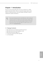
... are using. In case any modiications of this motherboard, please visit our website for purchasing ASRock B85 Anniversary motherboard, a reliable motherboard produced under ASRock's consistently stringent quality control. ASRock website http://www.asrock.com. 1.1 Package Contents • ASRock B85 Anniversary Motherboard (ATX Form Factor) • ASRock B85 Anniversary Quick Installation Guide • ASRock B85 Anniversary Support CD • 2 x Serial ATA (SATA) Data Cables (Optional) • 1 x I/O Panel Shield 5 English You may ind the latest VGA cards and CPU support list on...
... are using. In case any modiications of this motherboard, please visit our website for purchasing ASRock B85 Anniversary motherboard, a reliable motherboard produced under ASRock's consistently stringent quality control. ASRock website http://www.asrock.com. 1.1 Package Contents • ASRock B85 Anniversary Motherboard (ATX Form Factor) • ASRock B85 Anniversary Quick Installation Guide • ASRock B85 Anniversary Support CD • 2 x Serial ATA (SATA) Data Cables (Optional) • 1 x I/O Panel Shield 5 English You may ind the latest VGA cards and CPU support list on...
Quick Installation Guide
Page 10
...; 1 x 8 pin 12V Power Connector • 1 x PCIe Power Connector • 1 x Front Panel Audio Connector • 1 x SPDIF Out Connector • 2 x USB 2.0 Headers (Support 4 USB 2.0 ports) (Supports ESD Protection (ASRock Full Spike Protection)) • 1 x USB 3.0 Header (Supports 2 USB 3.0 ports) (Supports ESD Protection (ASRock Full Spike Protection)) BIOS Feature • 32Mb AMI UEFI Legal BIOS with multilingual GUI support • ACPI 1.1 Compliant wake up events • SMBIOS 2.3.1 support • CPU, DRAM, PCH 1.05V Voltage multi-adjustment Hardware Monitor • CPU/Chassis...
...; 1 x 8 pin 12V Power Connector • 1 x PCIe Power Connector • 1 x Front Panel Audio Connector • 1 x SPDIF Out Connector • 2 x USB 2.0 Headers (Support 4 USB 2.0 ports) (Supports ESD Protection (ASRock Full Spike Protection)) • 1 x USB 3.0 Header (Supports 2 USB 3.0 ports) (Supports ESD Protection (ASRock Full Spike Protection)) BIOS Feature • 32Mb AMI UEFI Legal BIOS with multilingual GUI support • ACPI 1.1 Compliant wake up events • SMBIOS 2.3.1 support • CPU, DRAM, PCH 1.05V Voltage multi-adjustment Hardware Monitor • CPU/Chassis...

Quick Installation Guide
Page 24
... connect a 4 pin molex power cable to this connector when more than three graphics cards are installed. his motherboard provides an 8-pin ATX 12V power connector. his connector supports Trusted Platform Module (TPM) system, which can securely store keys, digital certiicates, passwords, and data. To use a 20-pin ATX power supply, please plug it along Pin 1 and Pin 13. Please connect the SPDIF_OUT connector of a HDMI VGA card to this header with a cable. To use a 4-pin ATX power supply, please plug it along Pin 1 and Pin 5. A TPM system also helps enhance network...
... connect a 4 pin molex power cable to this connector when more than three graphics cards are installed. his motherboard provides an 8-pin ATX 12V power connector. his connector supports Trusted Platform Module (TPM) system, which can securely store keys, digital certiicates, passwords, and data. To use a 20-pin ATX power supply, please plug it along Pin 1 and Pin 13. Please connect the SPDIF_OUT connector of a HDMI VGA card to this header with a cable. To use a 4-pin ATX power supply, please plug it along Pin 1 and Pin 5. A TPM system also helps enhance network...


