
Software/BIOS Setup Guide
Page 5
...; Auto Driver Installer (ADI) • ASRock Live Update & APP Shop • ASRock Motherboard Utility (A-Tuning) • ASRock Motherboard Utility (Phantom Gaming Tuning) • ASRock Polychrome SYNC • Nahimic Audio BIOS Setup Guide • UEFI Setup Utility Because the motherboard specifications and the software might be subject to this documentation will be available on ASRock's website without notice. Intel Z790/H770/B760 Series Chapter 1 Introduction This user guide is a complete setup guide for specific information about the model you purchased. Settings and options...
...; Auto Driver Installer (ADI) • ASRock Live Update & APP Shop • ASRock Motherboard Utility (A-Tuning) • ASRock Motherboard Utility (Phantom Gaming Tuning) • ASRock Polychrome SYNC • Nahimic Audio BIOS Setup Guide • UEFI Setup Utility Because the motherboard specifications and the software might be subject to this documentation will be available on ASRock's website without notice. Intel Z790/H770/B760 Series Chapter 1 Introduction This user guide is a complete setup guide for specific information about the model you purchased. Settings and options...

Software/BIOS Setup Guide
Page 7
...-step-install the latest drivers simply from ASRock Auto Driver Installer?". An available Internet connection is no need to run the application again, please enable the "Auto Driver Installer" item in the BIOS. 2. If you would like to change the setting in the BIOS setting. Intel Z790/H770/B760 Series Step 2 Boot into the system without Internet, the Auto Driver Installer won't appear. The Auto Driver Installer will automatically pop up in the BIOS is enabled by default;
...-step-install the latest drivers simply from ASRock Auto Driver Installer?". An available Internet connection is no need to run the application again, please enable the "Auto Driver Installer" item in the BIOS. 2. If you would like to change the setting in the BIOS setting. Intel Z790/H770/B760 Series Step 2 Boot into the system without Internet, the Auto Driver Installer won't appear. The Auto Driver Installer will automatically pop up in the BIOS is enabled by default;
Software/BIOS Setup Guide
Page 29
... motherboard you power on . The battery on the system chassis. Intel Z790/H770/B760 Series Chapter 3 UEFI SETUP UTILITY 3.1 Introduction ASRock UEFI (Unified Extensible Firmware Interface) is turned off and then back on. We strongly recommend that inadequate BIOS settings may also restart by pressing the reset button on the motherboard supplies the power needed to configure all the supported system. This setup guide explains how to use the UEFI SETUP UTILITY to the CMOS when the system power is a BIOS utility...
... motherboard you power on . The battery on the system chassis. Intel Z790/H770/B760 Series Chapter 3 UEFI SETUP UTILITY 3.1 Introduction ASRock UEFI (Unified Extensible Firmware Interface) is turned off and then back on. We strongly recommend that inadequate BIOS settings may also restart by pressing the reset button on the motherboard supplies the power needed to configure all the supported system. This setup guide explains how to use the UEFI SETUP UTILITY to the CMOS when the system power is a BIOS utility...
Software/BIOS Setup Guide
Page 37
... to switch between multiple frequencies and voltage points for hardware controlled P-states. Enabling will still be fixed when Intel SpeedStep Technology is set to Disabled and Intel Turbo Boost Technology is set to [Enabled]. UnderVolt Protection When UnderVolt Protection is set to Enabled. Configuration options: [Enabled] [Disabled] Intel Turbo Boost Technology Intel Turbo Boost Technology enables the processor to 63. Configuration options: [Enabled] [Disabled] Intel Speed Shift Technology Allows you to enable or disable FLL Overclock Mode. Intel Z790/H770/B760 Series...
... to switch between multiple frequencies and voltage points for hardware controlled P-states. Enabling will still be fixed when Intel SpeedStep Technology is set to Disabled and Intel Turbo Boost Technology is set to [Enabled]. UnderVolt Protection When UnderVolt Protection is set to Enabled. Configuration options: [Enabled] [Disabled] Intel Turbo Boost Technology Intel Turbo Boost Technology enables the processor to 63. Configuration options: [Enabled] [Disabled] Intel Speed Shift Technology Allows you to enable or disable FLL Overclock Mode. Intel Z790/H770/B760 Series...
Software/BIOS Setup Guide
Page 67
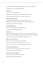
... on your motherboard. Configuration options: [Enabled] [Disabled] Intel(R) Ethernet Connection I226-V Allows you to enable or disable Onboard LAN. IGPU Multi-Monitor Select [Disabled] to configure the PCH DMI ASPM Setting. Intel Z790/H770/B760 Series DMI ASPM Support Allows you to disable the integrated graphics when an external graphics card is allocated to the integrated graphics processor when the system boots up. Configuration options: [Enabled] [Disabled] Share Memory Allows you use on the memory you to configure the size of memory that is installed.
... on your motherboard. Configuration options: [Enabled] [Disabled] Intel(R) Ethernet Connection I226-V Allows you to enable or disable Onboard LAN. IGPU Multi-Monitor Select [Disabled] to configure the PCH DMI ASPM Setting. Intel Z790/H770/B760 Series DMI ASPM Support Allows you to disable the integrated graphics when an external graphics card is allocated to the integrated graphics processor when the system boots up. Configuration options: [Enabled] [Disabled] Share Memory Allows you use on the memory you to configure the size of memory that is installed.
Software/BIOS Setup Guide
Page 68
... you to enable or disable audio for the onboard digital outputs. We recommend disabling Deep Sleep for power saving when the computer is installed. Configuration options: [Auto] [Enabled] [Disabled] Front Panel Allows you to select Front Panel type. [HD] sets the front panel audio connector mode to high definition audio. [AC 97] sets the front panel audio connector mode to legacy AC'97.] Onboard HDMI HD Audio Allows you to turn on your motherboard. Configuration options: [Enabled] [Disabled] Restore Onboard LED Default Allows you to configure deep sleep mode for better...
... you to enable or disable audio for the onboard digital outputs. We recommend disabling Deep Sleep for power saving when the computer is installed. Configuration options: [Auto] [Enabled] [Disabled] Front Panel Allows you to select Front Panel type. [HD] sets the front panel audio connector mode to high definition audio. [AC 97] sets the front panel audio connector mode to legacy AC'97.] Onboard HDMI HD Audio Allows you to turn on your motherboard. Configuration options: [Enabled] [Disabled] Restore Onboard LED Default Allows you to configure deep sleep mode for better...
Software/BIOS Setup Guide
Page 71
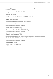
... set to VMD. Configuration options: [Enabled] [Disabled] Root Port BDF details Displays the Root Port BDF details. 67 Configuration options: [Enabled] [Disabled] Enable VMD Global Mapping Allows you to map or unmap this Root Port under VMD Allows you to detect and report on various indicators of reliability. Intel Z790/H770/B760 Series monitoring system for VMD configurations. Configuration options: [Enabled] [Disabled] VMD Configuration Press [Enter] to view the followings items for computer hard disk drives to enable...
... set to VMD. Configuration options: [Enabled] [Disabled] Root Port BDF details Displays the Root Port BDF details. 67 Configuration options: [Enabled] [Disabled] Enable VMD Global Mapping Allows you to map or unmap this Root Port under VMD Allows you to detect and report on various indicators of reliability. Intel Z790/H770/B760 Series monitoring system for VMD configurations. Configuration options: [Enabled] [Disabled] VMD Configuration Press [Enter] to view the followings items for computer hard disk drives to enable...

Software/BIOS Setup Guide
Page 77
Configuration options: [Enabled] [Disabled] 73 The XHCI ownership change should be claimed by XHCI driver. This item appears only for the motherboard that supports the PS/2 port. [Auto] disables legacy support if no USB devices are connected. [Disabled] keeps USB devices available only for USB devices. 3.4.7 USB Configuration Intel Z790/H770/B760 Series Legacy USB Support Allows you to enable or disable Legacy OS Support for EFI applications. [UEFI Setup Only] sets to support USB devices under the UEFI setup and Windows/Linux operating systems only. XHCI Hand-off This is a workaround...
Configuration options: [Enabled] [Disabled] 73 The XHCI ownership change should be claimed by XHCI driver. This item appears only for the motherboard that supports the PS/2 port. [Auto] disables legacy support if no USB devices are connected. [Disabled] keeps USB devices available only for USB devices. 3.4.7 USB Configuration Intel Z790/H770/B760 Series Legacy USB Support Allows you to enable or disable Legacy OS Support for EFI applications. [UEFI Setup Only] sets to support USB devices under the UEFI setup and Windows/Linux operating systems only. XHCI Hand-off This is a workaround...

Software/BIOS Setup Guide
Page 80
Please setup network configuration before using UEFI Tech Service. Auto Driver Installer Allows you are having trouble with available Internet access, the Auto Driver Installer tool will be permanently destroyed on the SSD and cannot be recovered. When it is enabled, after entering to securely erase SSD. This tool only lists the SSDs that support the Secure Erase function. UEFI Tech Service Contact ASRock Tech Service if you to download and install all user data will...
Please setup network configuration before using UEFI Tech Service. Auto Driver Installer Allows you are having trouble with available Internet access, the Auto Driver Installer tool will be permanently destroyed on the SSD and cannot be recovered. When it is enabled, after entering to securely erase SSD. This tool only lists the SSDs that support the Secure Erase function. UEFI Tech Service Contact ASRock Tech Service if you to download and install all user data will...

Software/BIOS Setup Guide
Page 91
... set Secure Boot Mode to clear all default Secure Boot keys. Use this item to [Custom]. This appears only when you load the default Secure Boot keys. Enroll SHA256 Hash certificate of Secure Boot variables to install factory default Secure Boot keys after the platform reset and while the System is in Secure Boot Mode. Platform Key(PK) Enroll Factory Defaults or load certificates from a file: 1. Key Management This item enables expert users to clear all default Secure Boot keys. Factory Key...
... set Secure Boot Mode to clear all default Secure Boot keys. Use this item to [Custom]. This appears only when you load the default Secure Boot keys. Enroll SHA256 Hash certificate of Secure Boot variables to install factory default Secure Boot keys after the platform reset and while the System is in Secure Boot Mode. Platform Key(PK) Enroll Factory Defaults or load certificates from a file: 1. Key Management This item enables expert users to clear all default Secure Boot keys. Factory Key...
User Manual
Page 3
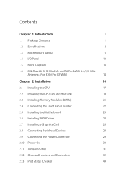
... Motherboard Layout 6 1.4 I/O Panel 10 1.5 Block Diagram 13 1.6 802.11ax Wi-Fi 6E Module and ASRock WiFi 2.4/5/6 GHz Antennas (For B760 Pro RS WiFi) 14 Chapter 2 Installation 16 2.1 Installing the CPU 17 2.2 Installing the CPU Fan and Heatsink 19 2.3 Installing Memory Modules (DIMM) 20 2.4 Connecting the Front Panel Header 22 2.5 Installing the Motherboard 23 2.6 Installing SATA Drives 24 2.7 Installing a Graphics Card 26 2.8 Connecting Peripheral Devices 28 2.9 Connecting the Power Connectors 29 2.10 Power On 30 2.11 Jumpers Setup 31 2.12 Onboard Headers and...
... Motherboard Layout 6 1.4 I/O Panel 10 1.5 Block Diagram 13 1.6 802.11ax Wi-Fi 6E Module and ASRock WiFi 2.4/5/6 GHz Antennas (For B760 Pro RS WiFi) 14 Chapter 2 Installation 16 2.1 Installing the CPU 17 2.2 Installing the CPU Fan and Heatsink 19 2.3 Installing Memory Modules (DIMM) 20 2.4 Connecting the Front Panel Header 22 2.5 Installing the Motherboard 23 2.6 Installing SATA Drives 24 2.7 Installing a Graphics Card 26 2.8 Connecting Peripheral Devices 28 2.9 Connecting the Power Connectors 29 2.10 Power On 30 2.11 Jumpers Setup 31 2.12 Onboard Headers and...
User Manual
Page 5
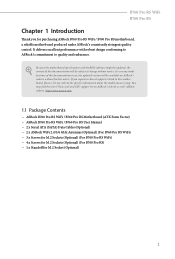
... are using. Because the motherboard specifications and the BIOS software might be updated, the content of this documentation occur, the updated version will be available on ASRock's website as well. If you require technical support related to this documentation will be subject to quality and endurance. ASRock website http://www.asrock.com. 1.1 Package Contents • ASRock B760 Pro RS WiFi / B760 Pro RS Motherboard (ATX Form Factor) • ASRock B760 Pro RS WiFi / B760 Pro RS User Manual • 2 x Serial ATA (SATA) Data Cables (Optional) • 2 x ASRock WiFi...
... are using. Because the motherboard specifications and the BIOS software might be updated, the content of this documentation occur, the updated version will be available on ASRock's website as well. If you require technical support related to this documentation will be subject to quality and endurance. ASRock website http://www.asrock.com. 1.1 Package Contents • ASRock B760 Pro RS WiFi / B760 Pro RS Motherboard (ATX Form Factor) • ASRock B760 Pro RS WiFi / B760 Pro RS User Manual • 2 x Serial ATA (SATA) Data Cables (Optional) • 2 x ASRock WiFi...
User Manual
Page 8
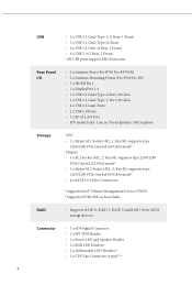
...M.2 Socket (M2_2, Key M), supports type 2260/2280 PCIe Gen4x2 (32 Gb/s) mode* • 1 x Hyper M.2 Socket (M2_3, Key M), supports type 2260/2280 PCIe Gen4x4 (64 Gb/s) mode* • 4 x SATA3 6.0 Gb/s Connectors * Supports Intel® Volume Management Device (VMD) * Supports NVMe SSD as boot disks RAID • Supports RAID 0, RAID 1, RAID 5 and RAID 10 for SATA storage devices Connector • 1 x eDP Signal Connector • 1 x SPI TPM Header • 1 x Power LED and Speaker Header • 2 x RGB LED Headers* • 2 x Addressable LED Headers** • 1 x CPU Fan Connector (4-pin...
...M.2 Socket (M2_2, Key M), supports type 2260/2280 PCIe Gen4x2 (32 Gb/s) mode* • 1 x Hyper M.2 Socket (M2_3, Key M), supports type 2260/2280 PCIe Gen4x4 (64 Gb/s) mode* • 4 x SATA3 6.0 Gb/s Connectors * Supports Intel® Volume Management Device (VMD) * Supports NVMe SSD as boot disks RAID • Supports RAID 0, RAID 1, RAID 5 and RAID 10 for SATA storage devices Connector • 1 x eDP Signal Connector • 1 x SPI TPM Header • 1 x Power LED and Speaker Header • 2 x RGB LED Headers* • 2 x Addressable LED Headers** • 1 x CPU Fan Connector (4-pin...
User Manual
Page 9
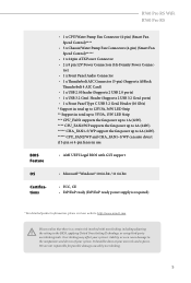
.... B760 Pro RS WiFi B760 Pro RS BIOS Feature OS Certifications • 1 x CPU/Water Pump Fan Connector (4-pin) (Smart Fan Speed Control)**** • 5 x Chassis/Water Pump Fan Connectors (4-pin) (Smart Fan Speed Control)***** • 1 x 24 pin ATX Power Connector • 2 x 8 pin 12V Power Connectors (Hi-Density Power Connec- Overclocking may affect your system's stability, or even cause damage to 2A (24W). ***** CPU_FAN2/WP and CHA_FAN1~5/WP can auto detect if 3-pin or 4-pin fan is in use. • AMI UEFI Legal BIOS with GUI support • Microsoft® Windows® 10 64-bit...
.... B760 Pro RS WiFi B760 Pro RS BIOS Feature OS Certifications • 1 x CPU/Water Pump Fan Connector (4-pin) (Smart Fan Speed Control)**** • 5 x Chassis/Water Pump Fan Connectors (4-pin) (Smart Fan Speed Control)***** • 1 x 24 pin ATX Power Connector • 2 x 8 pin 12V Power Connectors (Hi-Density Power Connec- Overclocking may affect your system's stability, or even cause damage to 2A (24W). ***** CPU_FAN2/WP and CHA_FAN1~5/WP can auto detect if 3-pin or 4-pin fan is in use. • AMI UEFI Legal BIOS with GUI support • Microsoft® Windows® 10 64-bit...
User Manual
Page 10
... CHA_FAN1/WP PCIE1 WiFi-802.11ax Module RoHS PCIE2 M2_WIFI CMOS Battery PCIE3 AUDIO CODEC HD_AUDIO1 1 RGB_LED1 1 ADDR_LED1 1 PCIE4 CLRMOS1 1 1 T B1 CHA_FAN3 /WP CHA_FAN2 /WP 27 26 25 24 23 22 21 M2_2 11 12 1 13 USB32_6_7 USB32_TC2 Intel B760 SATA3_2 SATA3_3 SATA3_0 SATA3_1 M2_3 SUPER I/O USB_3_4 1 BIOS ROM BOOT CPU DRAM VGA SPI_TPM_J1 1 SPK_PLED1 PANEL1 PLED PWRBTN 1 1 HDLED RESET 14 15...
... CHA_FAN1/WP PCIE1 WiFi-802.11ax Module RoHS PCIE2 M2_WIFI CMOS Battery PCIE3 AUDIO CODEC HD_AUDIO1 1 RGB_LED1 1 ADDR_LED1 1 PCIE4 CLRMOS1 1 1 T B1 CHA_FAN3 /WP CHA_FAN2 /WP 27 26 25 24 23 22 21 M2_2 11 12 1 13 USB32_6_7 USB32_TC2 Intel B760 SATA3_2 SATA3_3 SATA3_0 SATA3_1 M2_3 SUPER I/O USB_3_4 1 BIOS ROM BOOT CPU DRAM VGA SPI_TPM_J1 1 SPK_PLED1 PANEL1 PLED PWRBTN 1 1 HDLED RESET 14 15...
User Manual
Page 11
.../WP PCIE1 M2_WIFI_CT1 RoHS PCIE2 M2_WIFI1 CMOS Battery PCIE3 AUDIO CODEC HD_AUDIO1 1 RGB_LED1 1 ADDR_LED1 1 PCIE4 CLRMOS1 1 1 T B1 CHA_FAN3 /WP CHA_FAN2 /WP 27 26 25 24 23 22 21 M2_2 11 12 1 13 USB32_6_7 USB32_TC2 Intel B760 SATA3_2 SATA3_3 SATA3_0 SATA3_1 M2_3 SUPER I/O USB_3_4 1 BIOS ROM BOOT CPU DRAM VGA SPI_TPM_J1 1 SPK_PLED1 PANEL1 PLED PWRBTN 1 1 HDLED RESET 14 15 16 17 20...
.../WP PCIE1 M2_WIFI_CT1 RoHS PCIE2 M2_WIFI1 CMOS Battery PCIE3 AUDIO CODEC HD_AUDIO1 1 RGB_LED1 1 ADDR_LED1 1 PCIE4 CLRMOS1 1 1 T B1 CHA_FAN3 /WP CHA_FAN2 /WP 27 26 25 24 23 22 21 M2_2 11 12 1 13 USB32_6_7 USB32_TC2 Intel B760 SATA3_2 SATA3_3 SATA3_0 SATA3_1 M2_3 SUPER I/O USB_3_4 1 BIOS ROM BOOT CPU DRAM VGA SPI_TPM_J1 1 SPK_PLED1 PANEL1 PLED PWRBTN 1 1 HDLED RESET 14 15 16 17 20...
User Manual
Page 13
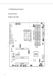
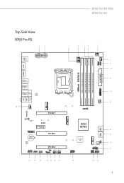
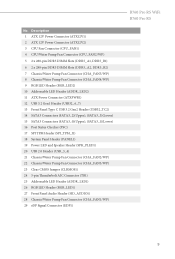
...) 16 Post Status Checker (PSC) 17 SPI TPM Header (SPI_TPM_J1) 18 System Panel Header (PANEL1) 19 Power LED and Speaker Header (SPK_PLED1) 20 USB 2.0 Header (USB_3_4) 21 Chassis/Water Pump Fan Connector (CHA_FAN2/WP) 22 Chassis/Water Pump Fan Connector (CHA_FAN3/WP) 23 Clear CMOS Jumper (CLRMOS1) 24 5-pin Thunderbolt AIC Connector (TB1) 25 Addressable LED Header (ADDR_LED1) 26 RGB LED Header (RGB_LED1) 27 Front Panel Audio Header (HD_AUDIO1) 28 Chassis/Water Pump Fan Connector (CHA_FAN1/WP) 29 eDP Signal Connector (EDP1) B760 Pro RS WiFi B760 Pro RS...
...) 16 Post Status Checker (PSC) 17 SPI TPM Header (SPI_TPM_J1) 18 System Panel Header (PANEL1) 19 Power LED and Speaker Header (SPK_PLED1) 20 USB 2.0 Header (USB_3_4) 21 Chassis/Water Pump Fan Connector (CHA_FAN2/WP) 22 Chassis/Water Pump Fan Connector (CHA_FAN3/WP) 23 Clear CMOS Jumper (CLRMOS1) 24 5-pin Thunderbolt AIC Connector (TB1) 25 Addressable LED Header (ADDR_LED1) 26 RGB LED Header (RGB_LED1) 27 Front Panel Audio Header (HD_AUDIO1) 28 Chassis/Water Pump Fan Connector (CHA_FAN1/WP) 29 eDP Signal Connector (EDP1) B760 Pro RS WiFi B760 Pro RS...
User Manual
Page 31
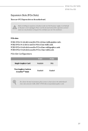
...the power cord is used for the card before you start the installation. PCIE3 (PCIe 4.0 x16 slot) is unplugged. PCIe Slot Configurations Single Graphics Card PCIE1 Gen5x16 PCIE3 N/A Two Graphics Cards in CrossFireTM Mode Gen5x16 Gen4x4 For a better thermal environment, please connect a chassis fan to the motherboard's chassis fan connector (CHA_FAN1~5/WP) when using multiple graphics cards. 27 PCIE4 (PCIe 3.0 x16 slot) is used for PCIe x4 lane width graphics cards. PCIe slots: PCIE1 (PCIe 5.0 x16 slot) is used for PCIe x16 lane width graphics cards. B760 Pro RS WiFi...
...the power cord is used for the card before you start the installation. PCIE3 (PCIe 4.0 x16 slot) is unplugged. PCIe Slot Configurations Single Graphics Card PCIE1 Gen5x16 PCIE3 N/A Two Graphics Cards in CrossFireTM Mode Gen5x16 Gen4x4 For a better thermal environment, please connect a chassis fan to the motherboard's chassis fan connector (CHA_FAN1~5/WP) when using multiple graphics cards. 27 PCIE4 (PCIe 3.0 x16 slot) is used for PCIe x4 lane width graphics cards. PCIe slots: PCIE1 (PCIe 5.0 x16 slot) is used for PCIe x16 lane width graphics cards. B760 Pro RS WiFi...
User Manual
Page 56
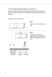
Nut Location PCB Length Module Type 1 A 6cm Type2260 2 B 8cm Type 2280 52 B A No. 2.15 M.2 SSD Module Installation Guide (M2_1) The M.2 is a small size and versatile card edge connector that aims to be used. Installing the M.2 SSD Module Step 1 Prepare a M.2 SSD module and the screw. 2 Step 2 1 Depending on the PCB type and length of your M.2 SSD module, find the corresponding nut location to replace mPCIe and mSATA. The Hyper M.2 Socket (M2_1, Key M) supports type 2260/2280 PCIe Gen4x4 (64 Gb/s) mode.
Nut Location PCB Length Module Type 1 A 6cm Type2260 2 B 8cm Type 2280 52 B A No. 2.15 M.2 SSD Module Installation Guide (M2_1) The M.2 is a small size and versatile card edge connector that aims to be used. Installing the M.2 SSD Module Step 1 Prepare a M.2 SSD module and the screw. 2 Step 2 1 Depending on the PCB type and length of your M.2 SSD module, find the corresponding nut location to replace mPCIe and mSATA. The Hyper M.2 Socket (M2_1, Key M) supports type 2260/2280 PCIe Gen4x4 (64 Gb/s) mode.
User Manual
Page 60
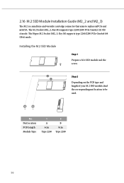
... Step 1 Prepare a M.2 SSD module and the screw. 2 Step 2 1 Depending on the PCB type and length of your M.2 SSD module, find the corresponding nut location to replace mPCIe and mSATA. The Hyper M.2 Socket (M2_3, Key M) supports type 2260/2280 PCIe Gen4x4 (64 Gb/s) mode. 2.16 M.2 SSD Module Installation Guide (M2_2 and M2_3) The M.2 is a small size and versatile card edge connector that aims to be used.
... Step 1 Prepare a M.2 SSD module and the screw. 2 Step 2 1 Depending on the PCB type and length of your M.2 SSD module, find the corresponding nut location to replace mPCIe and mSATA. The Hyper M.2 Socket (M2_3, Key M) supports type 2260/2280 PCIe Gen4x4 (64 Gb/s) mode. 2.16 M.2 SSD Module Installation Guide (M2_2 and M2_3) The M.2 is a small size and versatile card edge connector that aims to be used.


