
User Manual
Page 3
... 16 2.3 CPU Installation 17 2.4 Installation of Heatsink and CPU fan 19 2.5 Installation of Memory Modules (DIMM 20 2.6 Expansion Slots (PCI and PCI Express Slots 21 2.7 Dual Monitor and Surround Display Features 22 2.8 Jumpers Setup 25 2.9 Onboard Headers and Connectors 26 2.10 Serial ATA (SATA) / Serial ATA2 (SATA2) / Serial ATA3 (SATA3) Hard Disks Installation 31 2.11 Hot Plug for SATA / SATA2 / SATA3 HDDs 31 2.12 SATA / SATA2 / SATA3 HDD Hot Plug Feature and Operation Guide 32 2.13 Driver Installation Guide 34 2.14 Installing Windows® 8 / 8 64-bit / 7 / 7 64-bit / VistaTM...
... 16 2.3 CPU Installation 17 2.4 Installation of Heatsink and CPU fan 19 2.5 Installation of Memory Modules (DIMM 20 2.6 Expansion Slots (PCI and PCI Express Slots 21 2.7 Dual Monitor and Surround Display Features 22 2.8 Jumpers Setup 25 2.9 Onboard Headers and Connectors 26 2.10 Serial ATA (SATA) / Serial ATA2 (SATA2) / Serial ATA3 (SATA3) Hard Disks Installation 31 2.11 Hot Plug for SATA / SATA2 / SATA3 HDDs 31 2.12 SATA / SATA2 / SATA3 HDD Hot Plug Feature and Operation Guide 32 2.13 Driver Installation Guide 34 2.14 Installing Windows® 8 / 8 64-bit / 7 / 7 64-bit / VistaTM...

User Manual
Page 4
... 3.4.1 CPU Configuration 43 3.4.2 North Bridge Configuration 45 3.4.3 South Bridge Configuration 46 3.4.4 Storage Configuration 47 3.4.5 Intel(R) Rapid Start Technology 48 3.4.6 Intel(R) Smart Connect Technology 49 3.4.7 Super IO Configuration 50 3.4.8 ACPI Configuration 51 3.4.9 USB Configuration 52 3.5 Tool 53 3.6 Hardware Health Event Monitoring Screen 56 3.7 Boot Screen 57 3.8 Security Screen 59 3.9 Exit Screen 60 4 Software Support 61 4.1 Install Operating System 61 4.2 Support CD Information 61 4.2.1 Running Support CD 61 4.2.2 Drivers Menu 61 4.2.3 Utilities Menu 61...
... 3.4.1 CPU Configuration 43 3.4.2 North Bridge Configuration 45 3.4.3 South Bridge Configuration 46 3.4.4 Storage Configuration 47 3.4.5 Intel(R) Rapid Start Technology 48 3.4.6 Intel(R) Smart Connect Technology 49 3.4.7 Super IO Configuration 50 3.4.8 ACPI Configuration 51 3.4.9 USB Configuration 52 3.5 Tool 53 3.6 Hardware Health Event Monitoring Screen 56 3.7 Boot Screen 57 3.8 Security Screen 59 3.9 Exit Screen 60 4 Software Support 61 4.1 Install Operating System 61 4.2 Support CD Information 61 4.2.1 Running Support CD 61 4.2.2 Drivers Menu 61 4.2.3 Utilities Menu 61...
User Manual
Page 5
... Windows® 8 / 8 64-bit / 7 / 7 64-bit / VistaTM / VistaTM 64-bit, it is recommended to set the BIOS option in Storage Configuration to quality and endurance. Chapter 1: Introduction Thank you are using. Because the motherboard specifications and the BIOS software might be updated, the content of this manual, chapter 1 and 2 contains introduction of the Support CD. www.asrock.com/support/index.asp 1.1 Package Contents ASRock B75M-DGS R2.0 Motherboard (Micro ATX Form Factor) ASRock B75M-DGS R2.0 Quick Installation Guide ASRock B75M-DGS R2.0 Support CD 2 x Serial ATA (SATA...
... Windows® 8 / 8 64-bit / 7 / 7 64-bit / VistaTM / VistaTM 64-bit, it is recommended to set the BIOS option in Storage Configuration to quality and endurance. Chapter 1: Introduction Thank you are using. Because the motherboard specifications and the BIOS software might be updated, the content of this manual, chapter 1 and 2 contains introduction of the Support CD. www.asrock.com/support/index.asp 1.1 Package Contents ASRock B75M-DGS R2.0 Motherboard (Micro ATX Form Factor) ASRock B75M-DGS R2.0 Quick Installation Guide ASRock B75M-DGS R2.0 Support CD 2 x Serial ATA (SATA...

User Manual
Page 8
... ports) - 1 x USB 3.0 header (supports 2 USB 3.0 ports) BIOS Feature - 64Mb AMI UEFI Legal BIOS with overclocking, including adjusting the setting in the BIOS, applying Untied Overclocking Technology, or using third-party overclocking tools. CPU/Chassis/Power Fan Tachometer - Supports jumperfree - CASE OPEN detection - FCC, CE, WHQL - ACPI 1.1 Compliance Wake Up Events - SMBIOS 2.3.1 Support - Drivers, Utilities, AntiVirus Software (Trial Version), CyberLink MediaEspresso 6.5 Trial, Google Chrome Browser and Toolbar Hardware - Chassis Temperature Sensing - Voltage Monitoring...
... ports) - 1 x USB 3.0 header (supports 2 USB 3.0 ports) BIOS Feature - 64Mb AMI UEFI Legal BIOS with overclocking, including adjusting the setting in the BIOS, applying Untied Overclocking Technology, or using third-party overclocking tools. CPU/Chassis/Power Fan Tachometer - Supports jumperfree - CASE OPEN detection - FCC, CE, WHQL - ACPI 1.1 Compliance Wake Up Events - SMBIOS 2.3.1 Support - Drivers, Utilities, AntiVirus Software (Trial Version), CyberLink MediaEspresso 6.5 Trial, Google Chrome Browser and Toolbar Hardware - Chassis Temperature Sensing - Voltage Monitoring...

User Manual
Page 10
... key to enter into the BIOS setup menu to update system BIOS without entering operating systems first like MSDOS or Windows®. This convenient BIOS update tool allows you to get the same OC settings. In Hardware Monitor, it fully utilizes the memory space that the USB flash drive or hard drive must use FAT32/16/12 file system. 10 Please be noted that cannot be used under Windows® OS 32-bit CPU. In XFast RAM...
... key to enter into the BIOS setup menu to update system BIOS without entering operating systems first like MSDOS or Windows®. This convenient BIOS update tool allows you to get the same OC settings. In Hardware Monitor, it fully utilizes the memory space that the USB flash drive or hard drive must use FAT32/16/12 file system. 10 Please be noted that cannot be used under Windows® OS 32-bit CPU. In XFast RAM...

User Manual
Page 14
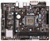
...) 3 ATX Power Connector (ATXPWR1) 4 1155-Pin CPU Socket 5 CPU Fan Connector (CPU_FAN1) 6 2 x 240-pin DDR3 DIMM Slots (DDR3_A1, DDR3_B1) 7 USB 3.0 Header (USB3_2_3) 8 SATA2 Connector (SATA2_1) 9 SATA3 Connector (SATA3_0) 10 SPI Flash Memory (64Mb) 11 PCI Express 3.0 x16 Slot (PCIE1) 12 Intel B75 Chipset 13 Clear CMOS Jumper (CLRCMOS1) 14 SATA2 Connector (SATA2_2) 15 SATA2 Connector (SATA2_3) 16 Chassis Speaker Header (SPEAKER1) 17 System Panel Header (PANEL1) 18 USB 2.0 Header (USB6_7) 19 USB 2.0 Header (USB4_5) 20 COM Port Header (COM1) 21 Print Port Header (LPT1) 22 Front Panel Audio Header...
...) 3 ATX Power Connector (ATXPWR1) 4 1155-Pin CPU Socket 5 CPU Fan Connector (CPU_FAN1) 6 2 x 240-pin DDR3 DIMM Slots (DDR3_A1, DDR3_B1) 7 USB 3.0 Header (USB3_2_3) 8 SATA2 Connector (SATA2_1) 9 SATA3 Connector (SATA3_0) 10 SPI Flash Memory (64Mb) 11 PCI Express 3.0 x16 Slot (PCIE1) 12 Intel B75 Chipset 13 Clear CMOS Jumper (CLRCMOS1) 14 SATA2 Connector (SATA2_2) 15 SATA2 Connector (SATA2_3) 16 Chassis Speaker Header (SPEAKER1) 17 System Panel Header (PANEL1) 18 USB 2.0 Header (USB6_7) 19 USB 2.0 Header (USB4_5) 20 COM Port Header (COM1) 21 Print Port Header (LPT1) 22 Front Panel Audio Header...

User Manual
Page 22
... monitor cable to D-Sub port on VGA card to your system already, you can easily enjoy the benefits of dual monitor function after your computer. 22 D-Sub port DVI-D port 2. With the internal VGA output support (DVI-D and D-Sub), you can drive same or different display contents. To enable dual monitor feature, please follow the below steps: 1. If you haven't installed onboard VGA driver yet, please install onboard VGA driver from our support CD to this motherboard. 2.7 Dual Monitor...
... monitor cable to D-Sub port on VGA card to your system already, you can easily enjoy the benefits of dual monitor function after your computer. 22 D-Sub port DVI-D port 2. With the internal VGA output support (DVI-D and D-Sub), you can drive same or different display contents. To enable dual monitor feature, please follow the below steps: 1. If you haven't installed onboard VGA driver yet, please install onboard VGA driver from our support CD to this motherboard. 2.7 Dual Monitor...

User Manual
Page 23
Then connect other monitor cables to enter UEFI setup. Press or to the corresponding connectors of the multi-monitor according to the steps below. Install the onboard VGA driver and the add-on PCIE1 slot. 3. B. Click "Apply" or "OK" to your card, one , two, three and four. 23 With the internal VGA output support (DVI-D and D-Sub) and external add-on PCI Express VGA cards, you can adjust the parameters of the...
Then connect other monitor cables to enter UEFI setup. Press or to the corresponding connectors of the multi-monitor according to the steps below. Install the onboard VGA driver and the add-on PCIE1 slot. 3. B. Click "Apply" or "OK" to your card, one , two, three and four. 23 With the internal VGA output support (DVI-D and D-Sub) and external add-on PCI Express VGA cards, you can adjust the parameters of the...

User Manual
Page 34
... Driver Installation Guide To install the drivers to your system, please insert the support CD to [IDE]. B. Set the option "SATA Mode Selection" to your system. 34 STEP 2: Install Windows® XP / XP 64-bit OS on your SATA / SATA2 / SATA3 HDDs without NCQ function STEP 1: Set Up UEFI. Therefore, the drivers you want to install Windows® XP / XP 64-bit OS on your optical drive first. Enter UEFI SETUP UTILITY Advanced screen Storage Configuration. Using SATA / SATA2 / SATA3 HDDs without RAID functions...
... Driver Installation Guide To install the drivers to your system, please insert the support CD to [IDE]. B. Set the option "SATA Mode Selection" to your system. 34 STEP 2: Install Windows® XP / XP 64-bit OS on your SATA / SATA2 / SATA3 HDDs without NCQ function STEP 1: Set Up UEFI. Therefore, the drivers you want to install Windows® XP / XP 64-bit OS on your optical drive first. Enter UEFI SETUP UTILITY Advanced screen Storage Configuration. Using SATA / SATA2 / SATA3 HDDs without RAID functions...

User Manual
Page 43
... [Enabled] to enable CPU internal thermal control mechanism to keep the CPU from the chipset. Set to enable in each processor package. Active Processor Cores Use this to enable or disable CPU C6 (ACPI C3) report to OS. In the C1 power state, the processor maintains the context of cores to [Enabled] if using Microsoft® Windows® XP, VistaTM, 7, 8, or Linux kernel version 2.4.18 or higher. No-Execute Memory Protection No-Execution (NX) Memory Protection Technology...
... [Enabled] to enable CPU internal thermal control mechanism to keep the CPU from the chipset. Set to enable in each processor package. Active Processor Cores Use this to enable or disable CPU C6 (ACPI C3) report to OS. In the C1 power state, the processor maintains the context of cores to [Enabled] if using Microsoft® Windows® XP, VistaTM, 7, 8, or Linux kernel version 2.4.18 or higher. No-Execute Memory Protection No-Execution (NX) Memory Protection Technology...

User Manual
Page 45
... Memory This allows you to select PCIE1 Link Speed. Render Standby Use this to enable/disable Intel(R) Virtualization Technology for Directed I/O. VT-d Use this item to enable or disable Render Standby by Internal Graphics Device. IGPU Multi-Monitor This allows you to enable or disable Deep Render Standby. Deep Render Standby This allows you to enable or disable IGPU Multi-Monitor. If you wish to select [Onboard], [PCI] or [PCI Express] as the boot graphic...
... Memory This allows you to select PCIE1 Link Speed. Render Standby Use this to enable/disable Intel(R) Virtualization Technology for Directed I/O. VT-d Use this item to enable or disable Render Standby by Internal Graphics Device. IGPU Multi-Monitor This allows you to enable or disable Deep Render Standby. Deep Render Standby This allows you to enable or disable IGPU Multi-Monitor. If you wish to select [Onboard], [PCI] or [PCI Express] as the boot graphic...

User Manual
Page 47
...feature. AHCI (Advanced Host Controller Interface) supports NCQ and other new features that will improve SATA disk performance but IDE mode does not have these advantages. The default value is [AHCI Mode]. 3.4.4 Storage Configuration SATA Controller(s) Use this item to enable or disable the S.M.A.R.T. (Self-Monitoring, Analysis, and Reporting Technology) feature. SATA Mode Selection Use this item to select SATA mode. Hard Disk S.M.A.R.T. SATA Aggressive Link Power Management Use this to configure SATA Aggressive Link Power Management. Configuration options: [IDE Mode], [AHCI Mode] and...
...feature. AHCI (Advanced Host Controller Interface) supports NCQ and other new features that will improve SATA disk performance but IDE mode does not have these advantages. The default value is [AHCI Mode]. 3.4.4 Storage Configuration SATA Controller(s) Use this item to enable or disable the S.M.A.R.T. (Self-Monitoring, Analysis, and Reporting Technology) feature. SATA Mode Selection Use this item to select SATA mode. Hard Disk S.M.A.R.T. SATA Aggressive Link Power Management Use this to configure SATA Aggressive Link Power Management. Configuration options: [IDE Mode], [AHCI Mode] and...

User Manual
Page 52
... have USB compatibility issues, it is [Enabled]. Legacy USB Support Use this item to select legacy support for USB 3.0 devices. Enables legacy support if USB devices are four configuration options: [Enabled], [Auto], [Disabled] and [UEFI Setup Only]. If you enable Fast Boot option. Legacy USB 3.0 Support Use this item to use under UEFI setup and Windows / Linux OS. Enables support for the details of USB 3.0 controller. There are connected. [Disabled] - The default value is recommended to select [Disabled] to enable or disable legacy support for USB devices. USB devices...
... have USB compatibility issues, it is [Enabled]. Legacy USB Support Use this item to select legacy support for USB 3.0 devices. Enables legacy support if USB devices are four configuration options: [Enabled], [Auto], [Disabled] and [UEFI Setup Only]. If you enable Fast Boot option. Legacy USB 3.0 Support Use this item to use under UEFI setup and Windows / Linux OS. Enables support for the details of USB 3.0 controller. There are connected. [Disabled] - The default value is recommended to select [Disabled] to enable or disable legacy support for USB devices. USB devices...

User Manual
Page 56
... to enable or disable case open has been detected. Clear Status This option appears only when the case open detection feature. 3.6 Hardware Health Event Monitoring Screen In this option to keep or clear the record of the CPU temperature, motherboard temperature, CPU fan speed, chassis fan speed, and the critical voltage. The default value is [Full On]. The default is value [Enabled]. Configuration options: [Full On] and [Automatic Mode]. Configuration options: [Full On], [Automatic Mode] and [Manual]. Chassis Fan 1 Setting This allows you to set chassis fan 1's speed.
... to enable or disable case open has been detected. Clear Status This option appears only when the case open detection feature. 3.6 Hardware Health Event Monitoring Screen In this option to keep or clear the record of the CPU temperature, motherboard temperature, CPU fan speed, chassis fan speed, and the critical voltage. The default value is [Full On]. The default is value [Enabled]. Configuration options: [Full On] and [Automatic Mode]. Configuration options: [Full On], [Automatic Mode] and [Manual]. Chassis Fan 1 Setting This allows you to set chassis fan 1's speed.

User Manual
Page 61
.... If the Main Menu does not appear automatically, locate and double click on a specific item then follow the installation wizard to display the menu. 4.2.2 Drivers Menu The Drivers Menu shows the available device's drivers if the system detects installed devices. Please install the necessary drivers to visit ASRock's website at http://www.asrock.com; Refer your computer. Because motherboard settings and hardware options vary, use the setup procedures in the Support CD to install it. 4.2.4 Contact...
.... If the Main Menu does not appear automatically, locate and double click on a specific item then follow the installation wizard to display the menu. 4.2.2 Drivers Menu The Drivers Menu shows the available device's drivers if the system detects installed devices. Please install the necessary drivers to visit ASRock's website at http://www.asrock.com; Refer your computer. Because motherboard settings and hardware options vary, use the setup procedures in the Support CD to install it. 4.2.4 Contact...

User Guide
Page 2
...) 3 ATX Power Connector (ATXPWR1) 4 1155-Pin CPU Socket 5 CPU Fan Connector (CPU_FAN1) 6 2 x 240-pin DDR3 DIMM Slots (DDR3_A1, DDR3_B1) 7 USB 3.0 Header (USB3_2_3) 8 SATA2 Connector (SATA2_1) 9 SATA3 Connector (SATA3_0) 10 SPI Flash Memory (64Mb) 11 PCI Express 3.0 x16 Slot (PCIE1) 12 Intel B75 Chipset 13 Clear CMOS Jumper (CLRCMOS1) 14 SATA2 Connector (SATA2_2) 15 SATA2 Connector (SATA2_3) 16 Chassis Speaker Header (SPEAKER1) 17 System Panel Header (PANEL1) 18 USB 2.0 Header (USB6_7) 19 USB 2.0 Header (USB4_5) 20 COM Port Header (COM1) 21 Print Port Header (LPT1) 22 Front Panel Audio Header...
...) 3 ATX Power Connector (ATXPWR1) 4 1155-Pin CPU Socket 5 CPU Fan Connector (CPU_FAN1) 6 2 x 240-pin DDR3 DIMM Slots (DDR3_A1, DDR3_B1) 7 USB 3.0 Header (USB3_2_3) 8 SATA2 Connector (SATA2_1) 9 SATA3 Connector (SATA3_0) 10 SPI Flash Memory (64Mb) 11 PCI Express 3.0 x16 Slot (PCIE1) 12 Intel B75 Chipset 13 Clear CMOS Jumper (CLRCMOS1) 14 SATA2 Connector (SATA2_2) 15 SATA2 Connector (SATA2_3) 16 Chassis Speaker Header (SPEAKER1) 17 System Panel Header (PANEL1) 18 USB 2.0 Header (USB6_7) 19 USB 2.0 Header (USB4_5) 20 COM Port Header (COM1) 21 Print Port Header (LPT1) 22 Front Panel Audio Header...
User Guide
Page 4
... the "User Manual" in the Support CD. For the BIOS setup, please refer to AHCI mode. It delivers excellent performance with robust design conforming to ASRock's commitment to quality and endurance. You may find the latest VGA cards and CPU support lists on ASRock website without notice. www.asrock.com/support/index.asp 1.1 Package Contents ASRock B75M-DGS R2.0 Motherboard (Micro ATX Form Factor) ASRock B75M-DGS R2.0 Quick Installation Guide ASRock B75M-DGS R2.0 Support CD 2 x Serial ATA (SATA) Data Cables (Optional) 1 x I/O Panel Shield ASRock Reminds You...
... the "User Manual" in the Support CD. For the BIOS setup, please refer to AHCI mode. It delivers excellent performance with robust design conforming to ASRock's commitment to quality and endurance. You may find the latest VGA cards and CPU support lists on ASRock website without notice. www.asrock.com/support/index.asp 1.1 Package Contents ASRock B75M-DGS R2.0 Motherboard (Micro ATX Form Factor) ASRock B75M-DGS R2.0 Quick Installation Guide ASRock B75M-DGS R2.0 Support CD 2 x Serial ATA (SATA) Data Cables (Optional) 1 x I/O Panel Shield ASRock Reminds You...

User Guide
Page 7
... components and devices of your own risk and expense. SMBIOS 2.3.1 Support - CPU Core, IGPU, DRAM, 1.8V PLL, VTT, VCCSA Voltage Multi-adjustment Support CD - Chassis Temperature Sensing - CASE OPEN detection - English 7 ASRock B75M-DGS R2.0 Motherboard Supports jumperfree - Adjust by overclocking. Microsoft® Windows® 8 / 8 64-bit / 7 / 7 64-bit / VistaTM / VistaTM 64-bit / XP / XP 64-bit compliant (see CAUTION 4) Certifications - CPU/Chassis Fan Multi-Speed Control - FCC, CE, WHQL - Voltage Monitoring: +12V, +5V, +3.3V, CPU Vcore OS...
... components and devices of your own risk and expense. SMBIOS 2.3.1 Support - CPU Core, IGPU, DRAM, 1.8V PLL, VTT, VCCSA Voltage Multi-adjustment Support CD - Chassis Temperature Sensing - CASE OPEN detection - English 7 ASRock B75M-DGS R2.0 Motherboard Supports jumperfree - Adjust by overclocking. Microsoft® Windows® 8 / 8 64-bit / 7 / 7 64-bit / VistaTM / VistaTM 64-bit / XP / XP 64-bit compliant (see CAUTION 4) Certifications - CPU/Chassis Fan Multi-Speed Control - FCC, CE, WHQL - Voltage Monitoring: +12V, +5V, +3.3V, CPU Vcore OS...
User Guide
Page 10
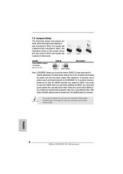
... power supply. 1.4 Jumpers Setup The illustration shows how jumpers are "Short" when jumper cap is placed on pins, the jumper is "Open". To clear and reset the system parameters to clear the record of previous chassis intrusion status. If you to short pin2 and pin3 on pins, the jumper is placed on these 2 pins. English 10 ASRock B75M-DGS R2.0 Motherboard Jumper Clear CMOS Jumper (CLRCMOS1) (see p.2, No. 13) Setting Default Clear CMOS Description Note: CLRCMOS1 allows you clear the CMOS, the case...
... power supply. 1.4 Jumpers Setup The illustration shows how jumpers are "Short" when jumper cap is placed on pins, the jumper is "Open". To clear and reset the system parameters to clear the record of previous chassis intrusion status. If you to short pin2 and pin3 on pins, the jumper is placed on these 2 pins. English 10 ASRock B75M-DGS R2.0 Motherboard Jumper Clear CMOS Jumper (CLRCMOS1) (see p.2, No. 13) Setting Default Clear CMOS Description Note: CLRCMOS1 allows you clear the CMOS, the case...
User Guide
Page 15
... drivers and useful utilities that detects if the chassis cover has been removed. It will enhance motherboard features. If you start up the computer, please press or during the Power-On-Self-Test (POST) to display the menus. 15 ASRock B75M-DGS R2.0 Motherboard English Serial port Header (9-pin COM1) (see p.2, No. 25) 1 GND Signal This motherboard supports CASE OPEN detection feature that will display the Main Menu automatically if "AUTORUN" is designed to enter BIOS Setup after POST...
... drivers and useful utilities that detects if the chassis cover has been removed. It will enhance motherboard features. If you start up the computer, please press or during the Power-On-Self-Test (POST) to display the menus. 15 ASRock B75M-DGS R2.0 Motherboard English Serial port Header (9-pin COM1) (see p.2, No. 25) 1 GND Signal This motherboard supports CASE OPEN detection feature that will display the Main Menu automatically if "AUTORUN" is designed to enter BIOS Setup after POST...


