Software/BIOS Setup Guide
Page 3
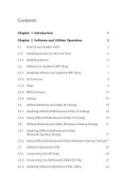
... 8 2.2.3 Apps 9 2.2.4 BIOS & Drivers 12 2.2.5 Setting 13 2.3 ASRock Motherboard Utility (A-Tuning) 14 2.3.1 Installing ASRock Motherboard Utility (A-Tuning) 14 2.3.2 Using ASRock Motherboard Utility (A-Tuning) 14 2.4 ASRock Motherboard Utility (Phantom Gaming Tuning) 17 2.4.1 Installing ASRock Motherboard Utility (Phantom Gaming Tuning) 17 2.4.2 Using ASRock Motherboard Utility (Phantom Gaming Tuning)17 2.5 ASRock Polychrome SYNC 20 2.5.1 Connecting the LED Strip 20 2.5.2 Connecting the Addressable RGB LED Strip 21 2.5.3 Installing ASRock Polychrome SYNC Utility 22
... 8 2.2.3 Apps 9 2.2.4 BIOS & Drivers 12 2.2.5 Setting 13 2.3 ASRock Motherboard Utility (A-Tuning) 14 2.3.1 Installing ASRock Motherboard Utility (A-Tuning) 14 2.3.2 Using ASRock Motherboard Utility (A-Tuning) 14 2.4 ASRock Motherboard Utility (Phantom Gaming Tuning) 17 2.4.1 Installing ASRock Motherboard Utility (Phantom Gaming Tuning) 17 2.4.2 Using ASRock Motherboard Utility (Phantom Gaming Tuning)17 2.5 ASRock Polychrome SYNC 20 2.5.1 Connecting the LED Strip 20 2.5.2 Connecting the Addressable RGB LED Strip 21 2.5.3 Installing ASRock Polychrome SYNC Utility 22
Software/BIOS Setup Guide
Page 5
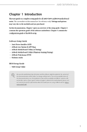
... case any modifications of the setup guide. If you require technical support related to this documentation occur, the updated version will be updated, the content of this documentation, Chapter 1 gives an overview of this motherboard, please visit our website for specific information about the model you purchased. AMD X670/B650 Series Chapter 1 Introduction This user guide is a complete setup guide for reference only. Software Setup Guide • Auto Driver Installer (ADI) • ASRock...
... case any modifications of the setup guide. If you require technical support related to this documentation occur, the updated version will be updated, the content of this documentation, Chapter 1 gives an overview of this motherboard, please visit our website for specific information about the model you purchased. AMD X670/B650 Series Chapter 1 Introduction This user guide is a complete setup guide for reference only. Software Setup Guide • Auto Driver Installer (ADI) • ASRock...
Software/BIOS Setup Guide
Page 7
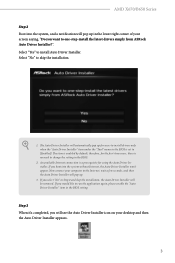
... enabled by default; If you will see the Auto Driver Installer icon on your computer to install drivers only when the "Auto Driver Installer" item under the "Tool" menu in the BIOS. 2. Now connect your desktop and then the Auto Driver Installer appears. 3 The item is a prerequisite for the first-time users, there is no need to change the setting in the BIOS is set to one-step-install the latest drivers simply from ASRock Auto Driver Installer...
... enabled by default; If you will see the Auto Driver Installer icon on your computer to install drivers only when the "Auto Driver Installer" item under the "Tool" menu in the BIOS. 2. Now connect your desktop and then the Auto Driver Installer appears. 3 The item is a prerequisite for the first-time users, there is no need to change the setting in the BIOS is set to one-step-install the latest drivers simply from ASRock Auto Driver Installer...
Software/BIOS Setup Guide
Page 9
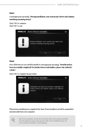
... "No" to complete the procedure. For further drivers and utilities, please visit ASRock's website." After driver installation, the Auto Driver Installer will be removed. If you would like to run the application again, please go to the "Tool" menu in the BIOS setting, and set the "Auto Driver Installer" item to continue. AMD X670/B650 Series Step 5 A messages pops up saying, "Installation has been successfully completed! Step 6 Once all...
... "No" to complete the procedure. For further drivers and utilities, please visit ASRock's website." After driver installation, the Auto Driver Installer will be removed. If you would like to run the application again, please go to the "Tool" menu in the BIOS setting, and set the "Auto Driver Installer" item to continue. AMD X670/B650 Series Step 5 A messages pops up saying, "Installation has been successfully completed! Step 6 Once all...

Software/BIOS Setup Guide
Page 29
... the UEFI default configurations or change the setting, try to clear the CMOS values and reset the board to boot after POST, restart the system by pressing + + , or by pressing the reset button on the system chassis. You may cause system instability, mulfunction or boot failure. This setup guide explains how to use the UEFI SETUP UTILITY to different BIOS release versions or CPU installed. The UEFI system works with a USB mouse and offers users a faster, sleeker experience. This BIOS utility can...
... the UEFI default configurations or change the setting, try to clear the CMOS values and reset the board to boot after POST, restart the system by pressing + + , or by pressing the reset button on the system chassis. You may cause system instability, mulfunction or boot failure. This setup guide explains how to use the UEFI SETUP UTILITY to different BIOS release versions or CPU installed. The UEFI system works with a USB mouse and offers users a faster, sleeker experience. This BIOS utility can...
Software/BIOS Setup Guide
Page 37
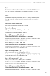
... clock in which CAS is asserted for a following write-burst operation. Power Down Enable Allows you to enable or disable DDR5 power down mode. Configuration options: [Auto] [RTT_OFF] [RZQ (240)] [RZQ/2 (120)] [RZQ/3 (80)] [RZQ/6 (60)] [RZQ/5 (48)] [RZQ/6 (40)] [RZQ/7 (34)] Dram ODT impedance RTT_PARK Allows you to specify the Dram ODT impedance RTT_PARK. DRAM Bus Control Configuration Press [Enter] to specify the Dram ODT impedance RTT_NOM_RD. Configuration options: [Auto] [Disabled] [Enabled] Dram...
... clock in which CAS is asserted for a following write-burst operation. Power Down Enable Allows you to enable or disable DDR5 power down mode. Configuration options: [Auto] [RTT_OFF] [RZQ (240)] [RZQ/2 (120)] [RZQ/3 (80)] [RZQ/6 (60)] [RZQ/5 (48)] [RZQ/6 (40)] [RZQ/7 (34)] Dram ODT impedance RTT_PARK Allows you to specify the Dram ODT impedance RTT_PARK. DRAM Bus Control Configuration Press [Enter] to specify the Dram ODT impedance RTT_NOM_RD. Configuration options: [Auto] [Disabled] [Enabled] Dram...
Software/BIOS Setup Guide
Page 48
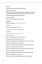
Configuration options: [Auto] [Disabled] [Enabled] PS2 Y-Cable Enable the PS2 Y-Cable or set this setting automatically. Configure the size of memory that is allocated to the integrated graphics processor when the system boots up. [Auto] BIOS will configure this option to Auto. Onboard HD Audio Allows you to enable or disable onboard HD audio. Downstream High Frequency Peak Port B Allows you to configure the Downstream High Frequency Peak Port B settings. Downstream Low Frequency Peak Port A Allows you to configure the Downstream Low Frequency Peak Port A settings. PCIe ...
Configuration options: [Auto] [Disabled] [Enabled] PS2 Y-Cable Enable the PS2 Y-Cable or set this setting automatically. Configure the size of memory that is allocated to the integrated graphics processor when the system boots up. [Auto] BIOS will configure this option to Auto. Onboard HD Audio Allows you to enable or disable onboard HD audio. Downstream High Frequency Peak Port B Allows you to configure the Downstream High Frequency Peak Port B settings. Downstream Low Frequency Peak Port A Allows you to configure the Downstream Low Frequency Peak Port A settings. PCIe ...
Software/BIOS Setup Guide
Page 57
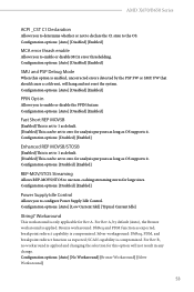
... compromized. Configuration options: [Disabled] [Enabled] Enhanced REP MOVSB/STOSB [Enabled] This is applied. Configuration options: [Auto] [Disabled] [Enabled] SMU and PSP Debug Mode When this option will hang and not reset the system. Configuration options: [Disabled] [Enabled] Power Supply Idle Control Allows you to zero for analysis purposes as long as default. [Disabled] This can be set to 1 as OS supports it . Silver workaground: DbReq, PDM, and breakpoint redirect function as expected; AMD X670/B650 Series ACPI _CST...
... compromized. Configuration options: [Disabled] [Enabled] Enhanced REP MOVSB/STOSB [Enabled] This is applied. Configuration options: [Auto] [Disabled] [Enabled] SMU and PSP Debug Mode When this option will hang and not reset the system. Configuration options: [Disabled] [Enabled] Power Supply Idle Control Allows you to zero for analysis purposes as long as default. [Disabled] This can be set to 1 as OS supports it . Silver workaground: DbReq, PDM, and breakpoint redirect function as expected; AMD X670/B650 Series ACPI _CST...
Software/BIOS Setup Guide
Page 65
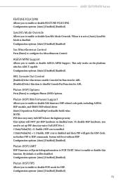
... enable or disable AGESA MPM Support. Select to disable ConsoleOut Function for ABL. [Disabled] Select this item to enable or disable this item to enable ConsoleOut Function for ABL. ABL Console Out Control [Enabled] Select this function. This option will boot without HSP. AMD X670/B650 Series FEATURE FCLK DPM Allows you need to set to [Auto], SyncFifo Mode is disabled and then PSP will gate the HSP clock...
... enable or disable AGESA MPM Support. Select to disable ConsoleOut Function for ABL. [Disabled] Select this item to enable or disable this item to enable ConsoleOut Function for ABL. ABL Console Out Control [Enabled] Select this function. This option will boot without HSP. AMD X670/B650 Series FEATURE FCLK DPM Allows you need to set to [Auto], SyncFifo Mode is disabled and then PSP will gate the HSP clock...

Software/BIOS Setup Guide
Page 68
Please set the "PCIe/GFX Lanes Configuration" item according to disable UCSI (USB Type-C Connector System Software Interface). Configuration options: [Auto] [Gen1]-[Gen4] UCSI Support [Eneble] Select this item to enable UCSI (USB Type-C Connector System Software Interface). [Disable] Select this item to the RAID configuration. Manully press cold reset button to configure PCIe x16 Link Speed. External CLK Control Allows you to configure External CLK Control. NVMe RAID mode Allows you to enable or disable NVMe RAID mode. Configuration options: [Disabled] [Enabled] Adjust ...
Please set the "PCIe/GFX Lanes Configuration" item according to disable UCSI (USB Type-C Connector System Software Interface). Configuration options: [Auto] [Gen1]-[Gen4] UCSI Support [Eneble] Select this item to enable UCSI (USB Type-C Connector System Software Interface). [Disable] Select this item to the RAID configuration. Manully press cold reset button to configure PCIe x16 Link Speed. External CLK Control Allows you to configure External CLK Control. NVMe RAID mode Allows you to enable or disable NVMe RAID mode. Configuration options: [Disabled] [Enabled] Adjust ...
Software/BIOS Setup Guide
Page 72
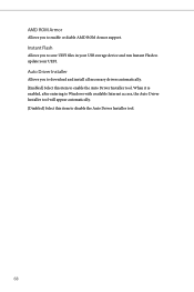
Instant Flash Allows you to save UEFI files in your UEFI. Auto Driver Installer Allows you to download and install all necessary drivers automatically. [Enabled] Select this item to enable or diable AMD ROM Armor support. AMD ROM Armor Allows you to disable the Auto Driver Installer tool. 68 When it is enabled, after entering to Windows with available Internet access, the Auto Driver Installer tool will appear automatically. [Disabled] Select this item to update your USB storage device and run Instant Flash to enable the Auto Driver Installer tool.
Instant Flash Allows you to save UEFI files in your UEFI. Auto Driver Installer Allows you to download and install all necessary drivers automatically. [Enabled] Select this item to enable or diable AMD ROM Armor support. AMD ROM Armor Allows you to disable the Auto Driver Installer tool. 68 When it is enabled, after entering to Windows with available Internet access, the Auto Driver Installer tool will appear automatically. [Disabled] Select this item to update your USB storage device and run Instant Flash to enable the Auto Driver Installer tool.
Software/BIOS Setup Guide
Page 80
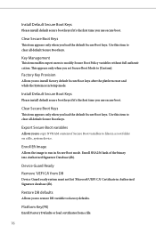
Key Management This item enables expert users to run in Secure Boot mode. Export Secure Boot variables Allows you use secure boot. Device Guard Ready Remove 'UEFI CA' from a file: 76 Install Default Secure Boot Keys Please install default secure boot keys if it 's the first time you load the default Secure Boot keys. Enroll SHA256 hash of Secure Boot variables to install factory default Secure Boot keys after the platform reset and while the System is in Setup mode. This appears only...
Key Management This item enables expert users to run in Secure Boot mode. Export Secure Boot variables Allows you use secure boot. Device Guard Ready Remove 'UEFI CA' from a file: 76 Install Default Secure Boot Keys Please install default secure boot keys if it 's the first time you load the default Secure Boot keys. Enroll SHA256 hash of Secure Boot variables to install factory default Secure Boot keys after the platform reset and while the System is in Setup mode. This appears only...

User Manual
Page 5
.... You may find the latest VGA cards and CPU support list on ASRock's website without notice. If you are using. ASRock website http://www.asrock.com. 1.1 Package Contents • ASRock B650E PG Riptide WiFi Motherboard (ATX Form Factor) • ASRock B650E PG Riptide WiFi User Manual • 2 x Serial ATA (SATA) Data Cables (Optional) • 2 x ASRock WiFi 2.4/5/6 GHz Antennas (Optional) • 2 x Screws for M.2 Sockets (Optional) • 1 x Graphics Card Holder (Optional) 1 English Because the motherboard specifications and the BIOS software might be updated, the content of this...
.... You may find the latest VGA cards and CPU support list on ASRock's website without notice. If you are using. ASRock website http://www.asrock.com. 1.1 Package Contents • ASRock B650E PG Riptide WiFi Motherboard (ATX Form Factor) • ASRock B650E PG Riptide WiFi User Manual • 2 x Serial ATA (SATA) Data Cables (Optional) • 2 x ASRock WiFi 2.4/5/6 GHz Antennas (Optional) • 2 x Screws for M.2 Sockets (Optional) • 1 x Graphics Card Holder (Optional) 1 English Because the motherboard specifications and the BIOS software might be updated, the content of this...
User Manual
Page 9
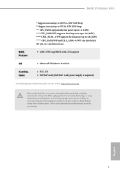
... auto detect if 3-pin or 4-pin fan is in use. • AMI UEFI Legal BIOS with GUI support OS Certifications • Microsoft® Windows® 11 64-bit • FCC, CE • ErP/EuP ready (ErP/EuP ready power supply is required) * For detailed product information, please visit our website: http://www.asrock.com Please realize that there is a certain risk involved with overclocking...
... auto detect if 3-pin or 4-pin fan is in use. • AMI UEFI Legal BIOS with GUI support OS Certifications • Microsoft® Windows® 11 64-bit • FCC, CE • ErP/EuP ready (ErP/EuP ready power supply is required) * For detailed product information, please visit our website: http://www.asrock.com Please realize that there is a certain risk involved with overclocking...

User Manual
Page 11
B650E PG Riptide WiFi No. Description 1 8 pin 12V Power Connector (ATX12V1) 2 4 pin 12V Power Connector (ATX12V2) 3 Chassis/Water Pump Fan Connector (CHA_FAN3/WP) 4 CPU Fan Connector (CPU_FAN1) 5 2 x 288-pin DDR5 DIMM Slots (DDR5_A1, DDR5_B1) 6 2 x 288-pin DDR5 DIMM Slots (DDR5_A2, DDR5_B2) 7 CPU/Water Pump Fan Connector (CPU_FAN2/WP) 8 Addressable LED Header (ADDR_LED2) 9 Addressable LED Header (ADDR_LED3) 10 Post Status Checker (PSC) 11 ATX Power Connector (ATXPWR1) 12 USB 3.2 Gen1 Header (USB32_4_5) 13 Front Panel Type C USB 3.2 Gen2x2 Header (USB32_TC_2) 14 SPI TPM Header (SPI_TPM_J1) 15 ...
B650E PG Riptide WiFi No. Description 1 8 pin 12V Power Connector (ATX12V1) 2 4 pin 12V Power Connector (ATX12V2) 3 Chassis/Water Pump Fan Connector (CHA_FAN3/WP) 4 CPU Fan Connector (CPU_FAN1) 5 2 x 288-pin DDR5 DIMM Slots (DDR5_A1, DDR5_B1) 6 2 x 288-pin DDR5 DIMM Slots (DDR5_A2, DDR5_B2) 7 CPU/Water Pump Fan Connector (CPU_FAN2/WP) 8 Addressable LED Header (ADDR_LED2) 9 Addressable LED Header (ADDR_LED3) 10 Post Status Checker (PSC) 11 ATX Power Connector (ATXPWR1) 12 USB 3.2 Gen1 Header (USB32_4_5) 13 Front Panel Type C USB 3.2 Gen2x2 Header (USB32_TC_2) 14 SPI TPM Header (SPI_TPM_J1) 15 ...
User Manual
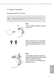
Page 17
... PC case. Please use the appropriate type based on the standoffs on the motherboard tray of screws in place. B650E PG Riptide WiFi 1.7 Graphics Card Holder Installing the Graphics Card Holder Before installing the Graphics Card Holder , please make sure that your motherboard is properly installed into a PC case. Step 1 Secure the Graphics Card Holder to the Graphics Card Holder with 2 screws. Then secure the bracket to the chassis with 1 screw. English 13 Type A Type B *There...
... PC case. Please use the appropriate type based on the standoffs on the motherboard tray of screws in place. B650E PG Riptide WiFi 1.7 Graphics Card Holder Installing the Graphics Card Holder Before installing the Graphics Card Holder , please make sure that your motherboard is properly installed into a PC case. Step 1 Secure the Graphics Card Holder to the Graphics Card Holder with 2 screws. Then secure the bracket to the chassis with 1 screw. English 13 Type A Type B *There...
User Manual
Page 43
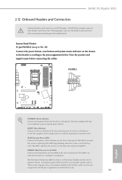
... panel. When connecting your system using the power button. B650E PG Riptide WiFi 2.12 Onboard Headers and Connectors Onboard headers and connectors are matched correctly. 39 English Note the positive and negative pins before connecting the cables. Press the reset button to restart the computer if the computer freezes and fails to the power button on the chassis front panel. A front panel module mainly consists of power button, reset button, power LED, hard drive activity LED, speaker and etc. Do NOT place jumper caps over the headers and connectors...
... panel. When connecting your system using the power button. B650E PG Riptide WiFi 2.12 Onboard Headers and Connectors Onboard headers and connectors are matched correctly. 39 English Note the positive and negative pins before connecting the cables. Press the reset button to restart the computer if the computer freezes and fails to the power button on the chassis front panel. A front panel module mainly consists of power button, reset button, power LED, hard drive activity LED, speaker and etc. Do NOT place jumper caps over the headers and connectors...

User Manual
Page 56
... the recovery key. Extract BIOS file from ASRock's website : http://www.asrock.com. 2. Then turn on the power supply's AC switch. *There is recommended to the root directory of your USB flash drive. If the recovery key is missing while encryption is not operating properly. Plug the 24 pin power connector to your USB flash drive must be FAT32. 3. Then the LED starts to blink. 8. ASRock BIOS Flashback feature allows you to update BIOS without CPU. Before using the BIOS Flashback...
... the recovery key. Extract BIOS file from ASRock's website : http://www.asrock.com. 2. Then turn on the power supply's AC switch. *There is recommended to the root directory of your USB flash drive. If the recovery key is missing while encryption is not operating properly. Plug the 24 pin power connector to your USB flash drive must be FAT32. 3. Then the LED starts to blink. 8. ASRock BIOS Flashback feature allows you to update BIOS without CPU. Before using the BIOS Flashback...
User Manual
Page 65
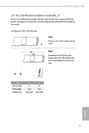
The Hyper M.2 Socket (M2_3, Key M) supports type 2260/2280 PCIe Gen4x4 (64 Gb/s) mode. Installing the M.2 SSD Module Step 1 Prepare a M.2 SSD module and the screw. B650E PG Riptide WiFi 2.17 M.2 SSD Module Installation Guide (M2_3) The M.2 is a small size and versatile card edge connector that aims to be used. No. Nut Location PCB Length Module Type 1 A 6cm Type 2260 2 B 8cm Type 2280 English 61 Step 2 Depending on the PCB type and length of your M.2 SSD module, find the corresponding nut location to replace mPCIe and mSATA.
The Hyper M.2 Socket (M2_3, Key M) supports type 2260/2280 PCIe Gen4x4 (64 Gb/s) mode. Installing the M.2 SSD Module Step 1 Prepare a M.2 SSD module and the screw. B650E PG Riptide WiFi 2.17 M.2 SSD Module Installation Guide (M2_3) The M.2 is a small size and versatile card edge connector that aims to be used. No. Nut Location PCB Length Module Type 1 A 6cm Type 2260 2 B 8cm Type 2280 English 61 Step 2 Depending on the PCB type and length of your M.2 SSD module, find the corresponding nut location to replace mPCIe and mSATA.

RAID Installation Guide
Page 13
It should list the USB drive as a UEFI device. Then restart the system. Please select this point. 13 When the disk selection page shows up during the Windows installation process, please click . Do not try to delete or create any partition at this picture. STEP 3: Windows installation Insert the USB drive with Windows 11 installation files. While the system is booting, please press [F11] to boot from. If the system restarts at this to open the boot menu that is shown in this point, then please open the [F11] boot menu again. 1.
It should list the USB drive as a UEFI device. Then restart the system. Please select this point. 13 When the disk selection page shows up during the Windows installation process, please click . Do not try to delete or create any partition at this picture. STEP 3: Windows installation Insert the USB drive with Windows 11 installation files. While the system is booting, please press [F11] to boot from. If the system restarts at this to open the boot menu that is shown in this point, then please open the [F11] boot menu again. 1.


