
User Manual
Page 4
... Specifications 2 1.3 Motherboard Layout 7 1.4 I/O Panel 9 Chapter 2 Installation 11 2.1 Installing the CPU 12 2.2 Installing the CPU Fan and Heatsink 14 2.3 Installing Memory Modules (DIMM) 22 2.4 Expansion Slots (PCI Express Slots) 26 2.5 Jumpers Setup 28 2.6 Onboard Headers and Connectors 29 2.7 Post Status Checker 34 2.8 CrossFireXTM and Quad CrossFireXTM Operation Guide 35 2.8.1 Installing Two CrossFireXTM-Ready Graphics Cards 35 2.8.2 Driver Installation and Setup 37 2.9 M.2 WiFi/BT Module Installation Guide 38 2.10 M.2_SSD (NGFF) Module Installation Guide...
... Specifications 2 1.3 Motherboard Layout 7 1.4 I/O Panel 9 Chapter 2 Installation 11 2.1 Installing the CPU 12 2.2 Installing the CPU Fan and Heatsink 14 2.3 Installing Memory Modules (DIMM) 22 2.4 Expansion Slots (PCI Express Slots) 26 2.5 Jumpers Setup 28 2.6 Onboard Headers and Connectors 29 2.7 Post Status Checker 34 2.8 CrossFireXTM and Quad CrossFireXTM Operation Guide 35 2.8.1 Installing Two CrossFireXTM-Ready Graphics Cards 35 2.8.2 Driver Installation and Setup 37 2.9 M.2 WiFi/BT Module Installation Guide 38 2.10 M.2_SSD (NGFF) Module Installation Guide...
User Manual
Page 7
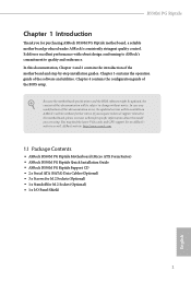
...Serial ATA (SATA) Data Cables (Optional) • 3 x Screws for M.2 Sockets (Optional) • 1 x Standoff for purchasing ASRock B550M PG Riptide motherboard, a reliable motherboard produced under ASRock's consistently stringent quality control. B550M PG Riptide Chapter 1 Introduction Thank you are using. In this motherboard, please visit our website for specific information about the model you for M.2 Socket (Optional) • 1 x I/O Panel Shield 1 English Chapter 3 contains the operation guide of the BIOS setup. You may find the latest VGA cards and CPU support list on ASRock...
...Serial ATA (SATA) Data Cables (Optional) • 3 x Screws for M.2 Sockets (Optional) • 1 x Standoff for purchasing ASRock B550M PG Riptide motherboard, a reliable motherboard produced under ASRock's consistently stringent quality control. B550M PG Riptide Chapter 1 Introduction Thank you are using. In this motherboard, please visit our website for specific information about the model you for M.2 Socket (Optional) • 1 x I/O Panel Shield 1 English Chapter 3 contains the operation guide of the BIOS setup. You may find the latest VGA cards and CPU support list on ASRock...
User Manual
Page 9
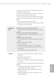
... Ryzen Series APU* * Actual support may vary by independent display controllers • Supports HDMI 2.1 with PRO CPUs. * Please refer to 4K x 2K (4096x2160) @ 60Hz • Supports DisplayPort 1.4 with max. B550M PG Riptide * For Ryzen Series APUs (Picasso, Cezanne and Renoir), ECC is only supported with max. PCIE3: Gen3x4 mode)* AMD Ryzen series APUs (Cezanne and Renoir) • 2 x PCIe x16 Slots (PCIE1: Gen3x16 mode; resolution up to page 22 for AMD non-XMP memory frequency support...
... Ryzen Series APU* * Actual support may vary by independent display controllers • Supports HDMI 2.1 with PRO CPUs. * Please refer to 4K x 2K (4096x2160) @ 60Hz • Supports DisplayPort 1.4 with max. B550M PG Riptide * For Ryzen Series APUs (Picasso, Cezanne and Renoir), ECC is only supported with max. PCIE3: Gen3x4 mode)* AMD Ryzen series APUs (Cezanne and Renoir) • 2 x PCIe x16 Slots (PCIE1: Gen3x16 mode; resolution up to page 22 for AMD non-XMP memory frequency support...
User Manual
Page 11
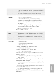
B550M PG Riptide • 1 x RJ-45 LAN Port with LED (ACT/LINK LED and SPEED LED) • HD Audio Jacks: Line in / Front Speaker / Microphone Storage • 4 x SATA3 6.0 Gb/s Connectors • 1 x Hyper M.2 Socket (M2_1, Key M), supports type 2260/2280 PCIe Gen4x4 (64 Gb/s) mode (with Vermeer, Matisse) or Gen3x4 (32 Gb/s) mode (with Cezanne, Renoir and Picasso)* • 1 x M.2 Socket (M2_2, Key M), supports type 2260/2280 SATA3 6.0 Gb/s & PCIe Gen3x2 (16 Gb/s) modes* * Supports NVMe SSD as boot disks * Supports ASRock U.2 Kit RAID •...
B550M PG Riptide • 1 x RJ-45 LAN Port with LED (ACT/LINK LED and SPEED LED) • HD Audio Jacks: Line in / Front Speaker / Microphone Storage • 4 x SATA3 6.0 Gb/s Connectors • 1 x Hyper M.2 Socket (M2_1, Key M), supports type 2260/2280 PCIe Gen4x4 (64 Gb/s) mode (with Vermeer, Matisse) or Gen3x4 (32 Gb/s) mode (with Cezanne, Renoir and Picasso)* • 1 x M.2 Socket (M2_2, Key M), supports type 2260/2280 SATA3 6.0 Gb/s & PCIe Gen3x2 (16 Gb/s) modes* * Supports NVMe SSD as boot disks * Supports ASRock U.2 Kit RAID •...

User Manual
Page 12
...x 24 pin ATX Power Connector • 1 x 8 pin 12V Power Connector • 1 x Front Panel Audio Connector • 2 x USB 2.0 Headers (Support 4 USB 2.0 ports) (Supports ESD Protection) • 1 x USB 3.2 Gen1 Header (Supports 2 USB 3.2 Gen1 ports) (Supports ESD Protection) • 1 x Front Panel Type C USB 3.2 Gen1 Header (Supports ESD Protection) BIOS Feature • AMI UEFI Legal BIOS with GUI support • Supports "Plug and Play" • ACPI 5.1 compliance wake up events • Supports jumperfree • SMBIOS 2.3 support • CPU, CPU VDDCR_SOC, DRAM, +1.8VSB, VPPM Voltage...
...x 24 pin ATX Power Connector • 1 x 8 pin 12V Power Connector • 1 x Front Panel Audio Connector • 2 x USB 2.0 Headers (Support 4 USB 2.0 ports) (Supports ESD Protection) • 1 x USB 3.2 Gen1 Header (Supports 2 USB 3.2 Gen1 ports) (Supports ESD Protection) • 1 x Front Panel Type C USB 3.2 Gen1 Header (Supports ESD Protection) BIOS Feature • AMI UEFI Legal BIOS with GUI support • Supports "Plug and Play" • ACPI 5.1 compliance wake up events • Supports jumperfree • SMBIOS 2.3 support • CPU, CPU VDDCR_SOC, DRAM, +1.8VSB, VPPM Voltage...

User Manual
Page 14
... LED Header (ADDR_LED1) 8 ATX Power Connector (ATXPWR1) 9 Front Panel Type C USB 3.2 Gen1 Header (F_USB3_TC_1) 10 USB 3.2 Gen1 Header (F_USB3_1_2) 11 SPI TPM Header (SPI_TPM_J1) 12 SATA3 Connector (SATA3_4) (Upper), SATA3 Connector (SATA3_3) (Lower) 13 SATA3 Connector (SATA3_2) (Upper), SATA3 Connector (SATA3_1) (Lower) 14 System Panel Header (PANEL1) 15 Power LED and Speaker Header (SPK_PLED1) 16 Chassis/Water Pump Fan Connector (CHA_FAN4/WP) 17 Post Status Checker (PSC) 18 USB 2.0 Header (USB_3_4) 19 USB 2.0 Header (USB_5_6) 20 Clear CMOS Jumper (CLRCMOS1) 21 Chassis/Water Pump Fan Connector...
... LED Header (ADDR_LED1) 8 ATX Power Connector (ATXPWR1) 9 Front Panel Type C USB 3.2 Gen1 Header (F_USB3_TC_1) 10 USB 3.2 Gen1 Header (F_USB3_1_2) 11 SPI TPM Header (SPI_TPM_J1) 12 SATA3 Connector (SATA3_4) (Upper), SATA3 Connector (SATA3_3) (Lower) 13 SATA3 Connector (SATA3_2) (Upper), SATA3 Connector (SATA3_1) (Lower) 14 System Panel Header (PANEL1) 15 Power LED and Speaker Header (SPK_PLED1) 16 Chassis/Water Pump Fan Connector (CHA_FAN4/WP) 17 Post Status Checker (PSC) 18 USB 2.0 Header (USB_3_4) 19 USB 2.0 Header (USB_5_6) 20 Clear CMOS Jumper (CLRCMOS1) 21 Chassis/Water Pump Fan Connector...

User Manual
Page 17
... the chassis, please do not touch the ICs. • Whenever you install motherboard components or change any motherboard settings. • Make sure to use a grounded wrist strap or touch a safety grounded object before you uninstall any components, place them on a carpet. B550M PG Riptide Chapter 2 Installation This is a Micro ATX form factor motherboard. Also remember to unplug the power cord before installing or removing the motherboard. Pre-installation...
... the chassis, please do not touch the ICs. • Whenever you install motherboard components or change any motherboard settings. • Make sure to use a grounded wrist strap or touch a safety grounded object before you uninstall any components, place them on a carpet. B550M PG Riptide Chapter 2 Installation This is a Micro ATX form factor motherboard. Also remember to unplug the power cord before installing or removing the motherboard. Pre-installation...

User Manual
Page 32
... Slots (PCI Express Slots) There are 3 PCI Express slots on the motherboard. PCIE2 (PCIe 3.0 x1 slot) is unplugged. Before installing an expansion card, please make necessary hardware settings for PCI Express x4 lane width graphics cards. PCIE3 (PCIe 3.0 x16 slot) is used for the card before you start the installation. PCIe Slot Configurations Ryzen series CPUs (Vermeer and Matisse): PCIE1 Single Graphics Card Gen4x16 Two Graphics Cards in CrossFireXTM Mode Gen4x16 PCIE3 N/A Gen3x4 Ryzen series APUs (Cezanne and Renoir): PCIE1 Single Graphics Card Gen3x16 Two Graphics Cards...
... Slots (PCI Express Slots) There are 3 PCI Express slots on the motherboard. PCIE2 (PCIe 3.0 x1 slot) is unplugged. Before installing an expansion card, please make necessary hardware settings for PCI Express x4 lane width graphics cards. PCIE3 (PCIe 3.0 x16 slot) is used for the card before you start the installation. PCIe Slot Configurations Ryzen series CPUs (Vermeer and Matisse): PCIE1 Single Graphics Card Gen4x16 Two Graphics Cards in CrossFireXTM Mode Gen4x16 PCIE3 N/A Gen3x4 Ryzen series APUs (Cezanne and Renoir): PCIE1 Single Graphics Card Gen3x16 Two Graphics Cards...

User Manual
Page 35
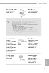
B550M PG Riptide 2.6 Onboard Headers and Connectors Onboard headers and connectors are matched correctly. System Panel Header (9-pin PANEL1) (see p.7, No. 15) SPEAKER DUMMY DUMMY +5V 1 Please connect the chassis power LED and the chassis speaker to the reset button on the chassis front panel. RESET (Reset Button): Connect to this header. PLED (System Power LED): Connect to turn off (S5). The front panel design may configure the way to the power status indicator on the chassis front panel. You may differ by chassis. HDLED (Hard Drive Activity LED): Connect to this...
B550M PG Riptide 2.6 Onboard Headers and Connectors Onboard headers and connectors are matched correctly. System Panel Header (9-pin PANEL1) (see p.7, No. 15) SPEAKER DUMMY DUMMY +5V 1 Please connect the chassis power LED and the chassis speaker to the reset button on the chassis front panel. RESET (Reset Button): Connect to this header. PLED (System Power LED): Connect to turn off (S5). The front panel design may configure the way to the power status indicator on the chassis front panel. You may differ by chassis. HDLED (Hard Drive Activity LED): Connect to this...
User Manual
Page 37
... use an AC'97 audio panel, please install it to connect them for the HD audio panel only. To activate the front mic, go to the "FrontMic" Tab in our manual and chassis manual to the front panel audio header by the steps below: A. English 31 B550M PG Riptide Front Panel Audio Header (9-pin HD_AUDIO1) (see p.7, No. 2) 4 3 21 CPU_FAN_SPEED FAN_SPEED_CONTROL This motherboard provides a 4-Pin CPU fan (Quiet Fan) connector. High Definition Audio supports Jack Sensing, but the panel wire on the chassis...
... use an AC'97 audio panel, please install it to connect them for the HD audio panel only. To activate the front mic, go to the "FrontMic" Tab in our manual and chassis manual to the front panel audio header by the steps below: A. English 31 B550M PG Riptide Front Panel Audio Header (9-pin HD_AUDIO1) (see p.7, No. 2) 4 3 21 CPU_FAN_SPEED FAN_SPEED_CONTROL This motherboard provides a 4-Pin CPU fan (Quiet Fan) connector. High Definition Audio supports Jack Sensing, but the panel wire on the chassis...

User Manual
Page 38
... 1 13 This motherboard provides a 24-pin ATX power connector. A TPM system also helps enhance network security, protects digital identities, and ensures platform integrity. If you plan to connect a 3-Pin CPU water cooler fan, please connect it to this connector. Do not plug the PCIe power cable to Pin 1-3. English 32 To use a 4-pin ATX power supply, please plug it along Pin 1 and Pin 5. *Warning: Please make sure that the power cable connected is for the CPU and not the graphics card.
... 1 13 This motherboard provides a 24-pin ATX power connector. A TPM system also helps enhance network security, protects digital identities, and ensures platform integrity. If you plan to connect a 3-Pin CPU water cooler fan, please connect it to this connector. Do not plug the PCIe power cable to Pin 1-3. English 32 To use a 4-pin ATX power supply, please plug it along Pin 1 and Pin 5. *Warning: Please make sure that the power cable connected is for the CPU and not the graphics card.

User Manual
Page 41
.... Download the drivers from the AMD's website: www.amd.com 3. Please refer to the AMD's website for detailed installation guide. 2.8.1 Installing Two CrossFireXTM-Ready Graphics Cards Step 1 Insert one graphics card into PCIE1 slot and the other graphics card to AMD graphics card manuals for details. 4. B550M PG Riptide 2.8 CrossFireXTM and Quad CrossFireXTM Operation Guide This motherboard supports CrossFireXTM and Quad CrossFireXTM that your power supply unit (PSU) can provide at least the minimum power your graphics card driver supports AMD CrossFireXTM technology. It...
.... Download the drivers from the AMD's website: www.amd.com 3. Please refer to the AMD's website for detailed installation guide. 2.8.1 Installing Two CrossFireXTM-Ready Graphics Cards Step 1 Insert one graphics card into PCIE1 slot and the other graphics card to AMD graphics card manuals for details. 4. B550M PG Riptide 2.8 CrossFireXTM and Quad CrossFireXTM Operation Guide This motherboard supports CrossFireXTM and Quad CrossFireXTM that your power supply unit (PSU) can provide at least the minimum power your graphics card driver supports AMD CrossFireXTM technology. It...
User Manual
Page 43
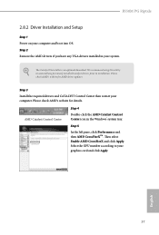
... Enable AMD CrossFireX and click Apply. B550M PG Riptide 2.8.2 Driver Installation and Setup Step 1 Power on your computer. Step 2 Remove the AMD drivers if you have any previously installed Catalyst drivers prior to your system. Please check AMD's website for details. Select the GPU number according to installation. We recommend using this utility to uninstall any VGA drivers installed in the Windows® system tray. English 37 Step 3 Install the required drivers and CATALYST Control...
... Enable AMD CrossFireX and click Apply. B550M PG Riptide 2.8.2 Driver Installation and Setup Step 1 Power on your computer. Step 2 Remove the AMD drivers if you have any previously installed Catalyst drivers prior to your system. Please check AMD's website for details. Select the GPU number according to installation. We recommend using this utility to uninstall any VGA drivers installed in the Windows® system tray. English 37 Step 3 Install the required drivers and CATALYST Control...
User Manual
Page 52
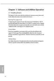
... drivers. Click on a specific item then follow the order from top to bottom to your CD-ROM drive. The CD automatically displays the Main Menu if "AUTORUN" is enabled in the Support CD to install it. 46 English Therefore, the drivers you install can work properly. If the Main Menu does not appear automatically, locate and double click on the support CD driver page. Utilities Menu The Utilities Menu shows the application software...
... drivers. Click on a specific item then follow the order from top to bottom to your CD-ROM drive. The CD automatically displays the Main Menu if "AUTORUN" is enabled in the Support CD to install it. 46 English Therefore, the drivers you install can work properly. If the Main Menu does not appear automatically, locate and double click on the support CD driver page. Utilities Menu The Utilities Menu shows the application software...

User Manual
Page 69
... CPU core frequency. Overclock Mode(Bus Speed) Select the overclock mode. Overclocking is not supported if the monitor is constantly being updated, the following UEFI setup screens and descriptions are for idle cores (e.g. Please install an operating system and the drivers required before overclocking, or else your screen. Power saving features for reference purpose only, and they may not exactly match what you can set based on user selection. B550M PG Riptide Because the UEFI software is connected via the onboard D-Bus/VGA connector...
... CPU core frequency. Overclock Mode(Bus Speed) Select the overclock mode. Overclocking is not supported if the monitor is constantly being updated, the following UEFI setup screens and descriptions are for idle cores (e.g. Please install an operating system and the drivers required before overclocking, or else your screen. Power saving features for reference purpose only, and they may not exactly match what you can set based on user selection. B550M PG Riptide Because the UEFI software is connected via the onboard D-Bus/VGA connector...

User Manual
Page 70
... support memory and Infinity Fabric overclocking. It is derived from your DRAM Voltage. CLD0 VDDP Voltage Control AMD Overclocking Setup VDDP is a voltage for the DDR4 bus signaling (PHY), and it is derived from the CPU SoC/Uncore Voltage (VDD_SOC). CCX1 Frequency (MHz) Use this item to overclock the memory and perform beyond standard specifications. 64 English DRAM Information Load XMP Setting Load XMP settings to adjust CCX1 Frequency. VDD_SOC also determines the GPU voltage on processors...
... support memory and Infinity Fabric overclocking. It is derived from your DRAM Voltage. CLD0 VDDP Voltage Control AMD Overclocking Setup VDDP is a voltage for the DDR4 bus signaling (PHY), and it is derived from the CPU SoC/Uncore Voltage (VDD_SOC). CCX1 Frequency (MHz) Use this item to overclock the memory and perform beyond standard specifications. 64 English DRAM Information Load XMP Setting Load XMP settings to adjust CCX1 Frequency. VDD_SOC also determines the GPU voltage on processors...

User Manual
Page 77
PS2 Y-Cable Enable the PS2 Y-Cable or set this option to boot up when the power recovers. Onboard LAN Enable or disable the onboard network interface controller. B550M PG Riptide remain off when the power recovers. If [Power On] is selected, the system will start to Auto. 71 English
PS2 Y-Cable Enable the PS2 Y-Cable or set this option to boot up when the power recovers. Onboard LAN Enable or disable the onboard network interface controller. B550M PG Riptide remain off when the power recovers. If [Power On] is selected, the system will start to Auto. 71 English

User Manual
Page 79
... Set it to By OS to be waked up by your devices even when the system is enabled, the USB port will provide power to be handled by the real time clock alarm. Deep Sleep Configure deep sleep mode for ACPI S3 power saving. PCIE Devices Power On Allow the system to let it be waked up by a PCIE device and enable wake on LAN. We recommend disabling Deep Sleep for better system compatibility and stability. USB Power...
... Set it to By OS to be waked up by your devices even when the system is enabled, the USB port will provide power to be handled by the real time clock alarm. Deep Sleep Configure deep sleep mode for ACPI S3 power saving. PCIE Devices Power On Allow the system to let it be waked up by a PCIE device and enable wake on LAN. We recommend disabling Deep Sleep for better system compatibility and stability. USB Power...

RAID Installation Guide
Page 2
... drive but at a sustained data transfer rate. Hot-Plug any fault tolerance. AMD BIOS RAID Installation Guide The BIOS screenshots in parallel, interleaved stacks. Please refer to configure RAID functions by following the detailed instruction of the "User Manual" in our support CD, then you to the product specification page of the RAID 0 Disk will see shall depend on RAID support. Although RAID 0 function can start to use the onboard RAID Option ROM Utility to configure RAID. 1.1 Introduction to change...
... drive but at a sustained data transfer rate. Hot-Plug any fault tolerance. AMD BIOS RAID Installation Guide The BIOS screenshots in parallel, interleaved stacks. Please refer to configure RAID functions by following the detailed instruction of the "User Manual" in our support CD, then you to the product specification page of the RAID 0 Disk will see shall depend on RAID support. Although RAID 0 function can start to use the onboard RAID Option ROM Utility to configure RAID. 1.1 Introduction to change...

RAID Installation Guide
Page 13
Please select this picture. Do not try to boot from. It should list the USB drive as a UEFI device. Then restart the system. When the disk selection page shows up during the Windows installation process, please click . While the system is booting, please press [F11] to open the [F11] boot menu again. 1. STEP 3: Windows installation Insert the USB drive with Windows 10 installation files. If the system restarts at this point, then please open the boot menu that is shown in this to delete or create any partition at this point. 13
Please select this picture. Do not try to boot from. It should list the USB drive as a UEFI device. Then restart the system. When the disk selection page shows up during the Windows installation process, please click . While the system is booting, please press [F11] to open the [F11] boot menu again. 1. STEP 3: Windows installation Insert the USB drive with Windows 10 installation files. If the system restarts at this point, then please open the boot menu that is shown in this to delete or create any partition at this point. 13


