
RAID Installation Guide
Page 2
...-Plug any fault tolerance. Although RAID 0 function can start to use the onboard RAID Option ROM Utility to configure RAID. 1.1 Introduction to RAID The term "RAID" stands for "Redundant Array of the data in our support CD, then you make a SATA driver diskette, press or to enter BIOS setup to set . After you can improve the access performance, it will direct all applications to a second drive. 1. AMD BIOS RAID Installation Guide AMD BIOS RAID Installation Guide is a method combining two or more hard disk drives...
...-Plug any fault tolerance. Although RAID 0 function can start to use the onboard RAID Option ROM Utility to configure RAID. 1.1 Introduction to RAID The term "RAID" stands for "Redundant Array of the data in our support CD, then you make a SATA driver diskette, press or to enter BIOS setup to set . After you can improve the access performance, it will direct all applications to a second drive. 1. AMD BIOS RAID Installation Guide AMD BIOS RAID Installation Guide is a method combining two or more hard disk drives...

RAID Installation Guide
Page 8
... "SATA Floppy Imaged driver" from ASRock's website A. STEP 4: Windows installation A. During Windows installation process, when Disk selection page show up, please click . C. Insert the Support CD into one of the USB port. Click to enter UEFI setup utility. During system boot, press or key to find the driver inside your USB flash disk. B. Plug a USB drive into the DVD-ROM drive. Go to finish the configuration. STEP 3.2: Download driver from ASRock's website and unzip the file into your USB flash drive. 8 D. STEP 3.1: Copy RAID driver to a USB flash drive You...
... "SATA Floppy Imaged driver" from ASRock's website A. STEP 4: Windows installation A. During Windows installation process, when Disk selection page show up, please click . C. Insert the Support CD into one of the USB port. Click to enter UEFI setup utility. During system boot, press or key to find the driver inside your USB flash disk. B. Plug a USB drive into the DVD-ROM drive. Go to finish the configuration. STEP 3.2: Download driver from ASRock's website and unzip the file into your USB flash drive. 8 D. STEP 3.1: Copy RAID driver to a USB flash drive You...

RAID Installation Guide
Page 14
A. Insert the Support CD into one of the USB port. B. D. Go to exit. Please download the "SATA Floppy Imaged driver" from ASRock's website A. Click to save to Tools Easy RAID Installer F. Plug a USB drive into the DVD-ROM drive. During system boot, press or key to finish the configuration. Select "Create Array". Please install the DVD-ROM. K. STEP 2.1: Copy RAID driver to a USB flash drive You can choose either STEP2.1 or STEP2.2 to enter UEFI setup utility. C. E. Follow instructions to finish the...
A. Insert the Support CD into one of the USB port. B. D. Go to exit. Please download the "SATA Floppy Imaged driver" from ASRock's website A. Click to save to Tools Easy RAID Installer F. Plug a USB drive into the DVD-ROM drive. During system boot, press or key to finish the configuration. Select "Create Array". Please install the DVD-ROM. K. STEP 2.1: Copy RAID driver to a USB flash drive You can choose either STEP2.1 or STEP2.2 to enter UEFI setup utility. C. E. Follow instructions to finish the...

RAID Installation Guide
Page 15
... the F11 boot menu again. It should list the USB drive as a UEFI device. A. Three drivers must be loaded. Click to boot from AMD website. Then restart the system. While this picture. Please select this point, then please open the boot menu that is the first. STEP 3: Windows installation Insert the USB drive with Windows 10 installation files. It might look different when using a different version driver package. 15 Using SATA/NVMe RAID driver package (version 9.2.0.127) from...
... the F11 boot menu again. It should list the USB drive as a UEFI device. A. Three drivers must be loaded. Click to boot from AMD website. Then restart the system. While this picture. Please select this point, then please open the boot menu that is the first. STEP 3: Windows installation Insert the USB drive with Windows 10 installation files. It might look different when using a different version driver package. 15 Using SATA/NVMe RAID driver package (version 9.2.0.127) from...

User Manual
Page 4
... Specifications 2 1.3 Motherboard Layout 7 1.4 I/O Panel 9 Chapter 2 Installation 10 2.1 Installing the CPU 11 2.2 Installing the CPU Fan and Heatsink 13 2.3 Installing Memory Modules (DIMM) 21 2.4 Expansion Slots (PCI Express Slots) 24 2.5 Jumpers Setup 25 2.6 Onboard Headers and Connectors 26 2.7 Post Status Checker 31 2.8 CrossFireXTM and Quad CrossFireXTM Operation Guide 32 2.8.1 Installing Two CrossFireXTM-Ready Graphics Cards 32 2.8.2 Driver Installation and Setup 34 2.9 M.2_SSD (NGFF) Module Installation Guide (M2_1) 35 2.10 M.2 WiFi/BT Module Installation...
... Specifications 2 1.3 Motherboard Layout 7 1.4 I/O Panel 9 Chapter 2 Installation 10 2.1 Installing the CPU 11 2.2 Installing the CPU Fan and Heatsink 13 2.3 Installing Memory Modules (DIMM) 21 2.4 Expansion Slots (PCI Express Slots) 24 2.5 Jumpers Setup 25 2.6 Onboard Headers and Connectors 26 2.7 Post Status Checker 31 2.8 CrossFireXTM and Quad CrossFireXTM Operation Guide 32 2.8.1 Installing Two CrossFireXTM-Ready Graphics Cards 32 2.8.2 Driver Installation and Setup 34 2.9 M.2_SSD (NGFF) Module Installation Guide (M2_1) 35 2.10 M.2 WiFi/BT Module Installation...
User Manual
Page 7
...-step installation guides. You may find the latest VGA cards and CPU support list on ASRock's website without notice. Chapter 4 contains the configuration guide of the software and utilities. In this motherboard, please visit our website for specific information about the model you are using. In case any modifications of this manual occur, the updated version will be available on ASRock's website as well. Because the motherboard specifications and the BIOS software might be updated, the...
...-step installation guides. You may find the latest VGA cards and CPU support list on ASRock's website without notice. Chapter 4 contains the configuration guide of the software and utilities. In this motherboard, please visit our website for specific information about the model you are using. In case any modifications of this manual occur, the updated version will be available on ASRock's website as well. Because the motherboard specifications and the BIOS software might be updated, the...

User Manual
Page 8
1.2 Specifications Platform CPU • ATX Form Factor • Solid Capacitor design • 2oz Copper PCB • Supports 3rd Gen AMD AM4 Ryzen™ / future AMD Ryzen™ Processors (3000 and 4000 Series Processors)* * Not compatible with AMD Ryzen™ 5 3400G and Ryzen™ 3 3200G. • Digi Power design • 8 Power Phase design Chipset • AMD B550 Memory • Dual Channel DDR4 Memory Technology • 4 x DDR4 DIMM Slots • AMD Ryzen series CPUs (Matisse) support DDR4 4533...
1.2 Specifications Platform CPU • ATX Form Factor • Solid Capacitor design • 2oz Copper PCB • Supports 3rd Gen AMD AM4 Ryzen™ / future AMD Ryzen™ Processors (3000 and 4000 Series Processors)* * Not compatible with AMD Ryzen™ 5 3400G and Ryzen™ 3 3200G. • Digi Power design • 8 Power Phase design Chipset • AMD B550 Memory • Dual Channel DDR4 Memory Technology • 4 x DDR4 DIMM Slots • AMD Ryzen series CPUs (Matisse) support DDR4 4533...

User Manual
Page 9
... boot disks • 2 x PCI Express 3.0 x1 Slots • Supports AMD Quad CrossFireXTM and CrossFireXTM • 1 x M.2 Socket (Key E), supports type 2230 WiFi/BT module Graphics • Integrated AMD RadeonTM Vega Series Graphics in Ryzen Series APU* * Actual support may vary by CPU • DirectX 12, Pixel Shader 5.0 • Shared memory default 2GB. resolution up to 4K x 2K (4096x2160) @ 60Hz • Supports Auto Lip Sync, Deep Color (12bpc), xvYCC and HBR (High Bit Rate Audio) with HDMI 2.1 Port (Compliant HDMI monitor...
... boot disks • 2 x PCI Express 3.0 x1 Slots • Supports AMD Quad CrossFireXTM and CrossFireXTM • 1 x M.2 Socket (Key E), supports type 2230 WiFi/BT module Graphics • Integrated AMD RadeonTM Vega Series Graphics in Ryzen Series APU* * Actual support may vary by CPU • DirectX 12, Pixel Shader 5.0 • Shared memory default 2GB. resolution up to 4K x 2K (4096x2160) @ 60Hz • Supports Auto Lip Sync, Deep Color (12bpc), xvYCC and HBR (High Bit Rate Audio) with HDMI 2.1 Port (Compliant HDMI monitor...

User Manual
Page 10
... • Supports Wake-On-LAN • Supports Lightning/ESD Protection • Supports Energy Efficient Ethernet 802.3az • Supports PXE Rear Panel I/O • Antenna Bracket • 1 x PS/2 Mouse/Keyboard Port • 1 x HDMI Port • 6 x USB 3.2 Gen1 Ports (Supports ESD Protection) • 1 x RJ-45 LAN Port with LED (ACT/LINK LED and SPEED LED) • HD Audio Jacks: Line in use, the other one will be disabled. • 1 x Hyper M.2 Socket (M2_1), supports M Key type 2260/2280/22110 M.2 PCI Express module...
... • Supports Wake-On-LAN • Supports Lightning/ESD Protection • Supports Energy Efficient Ethernet 802.3az • Supports PXE Rear Panel I/O • Antenna Bracket • 1 x PS/2 Mouse/Keyboard Port • 1 x HDMI Port • 6 x USB 3.2 Gen1 Ports (Supports ESD Protection) • 1 x RJ-45 LAN Port with LED (ACT/LINK LED and SPEED LED) • HD Audio Jacks: Line in use, the other one will be disabled. • 1 x Hyper M.2 Socket (M2_1), supports M Key type 2260/2280/22110 M.2 PCI Express module...

User Manual
Page 11
... x 24 pin ATX Power Connector • 1 x 8 pin 12V Power Connector • 1 x 4 pin 12V Power Connector • 1 x Front Panel Audio Connector • 2 x USB 2.0 Headers (Support 4 USB 2.0 ports) (Supports ESD Protection) • 1 x USB 3.2 Gen1 Header (Supports 2 USB 3.2 Gen1 ports) (Supports ESD Protection) BIOS Feature • AMI UEFI Legal BIOS with GUI support • Supports "Plug and Play" • ACPI 5.1 compliance wake up events • Supports jumperfree • SMBIOS 2.3 support • CPU, CPU VDDCR_SOC, DRAM, VPPM, 1.05V_PROM_S5, 2.5V_PROM, +1.8VSB, VDDP Voltage Multi...
... x 24 pin ATX Power Connector • 1 x 8 pin 12V Power Connector • 1 x 4 pin 12V Power Connector • 1 x Front Panel Audio Connector • 2 x USB 2.0 Headers (Support 4 USB 2.0 ports) (Supports ESD Protection) • 1 x USB 3.2 Gen1 Header (Supports 2 USB 3.2 Gen1 ports) (Supports ESD Protection) BIOS Feature • AMI UEFI Legal BIOS with GUI support • Supports "Plug and Play" • ACPI 5.1 compliance wake up events • Supports jumperfree • SMBIOS 2.3 support • CPU, CPU VDDCR_SOC, DRAM, VPPM, 1.05V_PROM_S5, 2.5V_PROM, +1.8VSB, VDDP Voltage Multi...

User Manual
Page 14
...-pin DDR4 DIMM Slots (DDR4_A2, DDR4_B2) 7 RGB LED Header (RGB_LED2) 8 Addressable LED Header (ADDR_LED2) 9 ATX Power Connector (ATXPWR1) 10 USB 3.2 Gen1 Header (USB3_7_8) 11 SPI TPM Header (SPI_TPM_J1) 12 SATA3 Connector (SATA3_5) 13 SATA3 Connector (SATA3_6) 14 SATA3 Connector (SATA3_3) 15 SATA3 Connector (SATA3_4) 16 SATA3 Connector (SATA3_1) 17 SATA3 Connector (SATA3_2) 18 Post Status Checker (PSC) 19 System Panel Header (PANEL1) 20 Power LED and Speaker Header (SPK_PLED1) 21 Chassis Fan / Waterpump Fan Connector (CHA_FAN1/WP) 22 Clear CMOS Jumper (CLRCMOS1...
...-pin DDR4 DIMM Slots (DDR4_A2, DDR4_B2) 7 RGB LED Header (RGB_LED2) 8 Addressable LED Header (ADDR_LED2) 9 ATX Power Connector (ATXPWR1) 10 USB 3.2 Gen1 Header (USB3_7_8) 11 SPI TPM Header (SPI_TPM_J1) 12 SATA3 Connector (SATA3_5) 13 SATA3 Connector (SATA3_6) 14 SATA3 Connector (SATA3_3) 15 SATA3 Connector (SATA3_4) 16 SATA3 Connector (SATA3_1) 17 SATA3 Connector (SATA3_2) 18 Post Status Checker (PSC) 19 System Panel Header (PANEL1) 20 Power LED and Speaker Header (SPK_PLED1) 21 Chassis Fan / Waterpump Fan Connector (CHA_FAN1/WP) 22 Clear CMOS Jumper (CLRCMOS1...
User Manual
Page 27
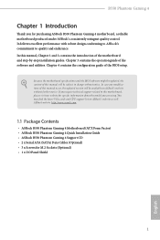
... into a DDR4 slot; DDR4 UDIMM Maximum Frequency Support Ryzen Series CPUs (Matisse): UDIMM Memory Slot A1 A2 B1 B2 Frequency (Mhz) - otherwise, this motherboard and DIMM may be damaged. SR 3200 - It is not allowed to install identical (the same brand, speed, size and chip-type) DDR4 DIMM pairs. 2. B550 Phantom Gaming 4 2.3 Installing Memory Modules (DIMM) This motherboard provides four 288-pin DDR4 (Double Data Rate 4) DIMM slots, and supports Dual Channel Memory Technology. 1. DR 3200...
... into a DDR4 slot; DDR4 UDIMM Maximum Frequency Support Ryzen Series CPUs (Matisse): UDIMM Memory Slot A1 A2 B1 B2 Frequency (Mhz) - otherwise, this motherboard and DIMM may be damaged. SR 3200 - It is not allowed to install identical (the same brand, speed, size and chip-type) DDR4 DIMM pairs. 2. B550 Phantom Gaming 4 2.3 Installing Memory Modules (DIMM) This motherboard provides four 288-pin DDR4 (Double Data Rate 4) DIMM slots, and supports Dual Channel Memory Technology. 1. DR 3200...

User Manual
Page 30
... make sure that the power supply is switched off or the power cord is used for PCI Express x16 lane width graphics cards. PCIe slots: PCIE1 (PCIe 4.0 x16 slot) is used for PCI Express x1 lane width cards. 2.4 Expansion Slots (PCI Express Slots) There are 4 PCI Express slots on the motherboard. English 24 Ryzen Series CPUs (Matisse) PCIE1 Gen4x16 PCIE3 Gen3x4 Ryzen Series APUs (Renoir) Gen3x16 Gen3x4 For a better thermal environment, please connect a chassis fan to the motherboard's chassis fan connector (CHA_FAN1/WP, CHA_FAN2...
... make sure that the power supply is switched off or the power cord is used for PCI Express x16 lane width graphics cards. PCIe slots: PCIE1 (PCIe 4.0 x16 slot) is used for PCI Express x1 lane width cards. 2.4 Expansion Slots (PCI Express Slots) There are 4 PCI Express slots on the motherboard. English 24 Ryzen Series CPUs (Matisse) PCIE1 Gen4x16 PCIE3 Gen3x4 Ryzen Series APUs (Renoir) Gen3x16 Gen3x4 For a better thermal environment, please connect a chassis fan to the motherboard's chassis fan connector (CHA_FAN1/WP, CHA_FAN2...
User Manual
Page 31
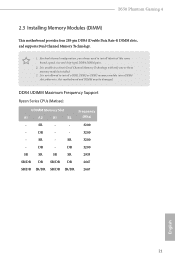
... the CMOS battery is "Short". If you update the BIOS. To clear and reset the system parameters to short the pins on CLRCMOS2 for 15 seconds, use a jumper cap to default setup, please turn off the computer and unplug the power cord from the power supply. After waiting for 5 seconds. However, please do the clear-CMOS action. Please remember toremove the jumper cap after you need to clear the data in CMOS. B550 Phantom Gaming 4 2.5 Jumpers Setup...
... the CMOS battery is "Short". If you update the BIOS. To clear and reset the system parameters to short the pins on CLRCMOS2 for 15 seconds, use a jumper cap to default setup, please turn off the computer and unplug the power cord from the power supply. After waiting for 5 seconds. However, please do the clear-CMOS action. Please remember toremove the jumper cap after you need to clear the data in CMOS. B550 Phantom Gaming 4 2.5 Jumpers Setup...
User Manual
Page 33
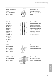
... ports. Each USB 3.2 Gen1 header can support two ports. If either one of them is one will be disabled. USB_PWR PP+ GND DUMMY 1 GND P+ PUSB_PWR There are two headers on this motherboard. USB 3.2 Gen1 Header (19-pin USB3_7_8) (see p.7, No. 23) SATA3_2 SATA3_4 SATA3_6 SATA3_1 SATA3_3 SATA3_5 SPEAKER DUMMY DUMMY +5V 1 PLED+ PLED+ PLED- English 27 B550 Phantom Gaming 4 Power LED and Speaker Header (7-pin SPK_PLED1) (see p.7, No. 20) Serial ATA3 Connectors...
... ports. Each USB 3.2 Gen1 header can support two ports. If either one of them is one will be disabled. USB_PWR PP+ GND DUMMY 1 GND P+ PUSB_PWR There are two headers on this motherboard. USB 3.2 Gen1 Header (19-pin USB3_7_8) (see p.7, No. 23) SATA3_2 SATA3_4 SATA3_6 SATA3_1 SATA3_3 SATA3_5 SPEAKER DUMMY DUMMY +5V 1 PLED+ PLED+ PLED- English 27 B550 Phantom Gaming 4 Power LED and Speaker Header (7-pin SPK_PLED1) (see p.7, No. 20) Serial ATA3 Connectors...

User Manual
Page 38
... with a 16-pipe card, both cards will operate as 12-pipe cards while in CrossFireXTM mode. 5. Make sure that your power supply unit (PSU) can provide at least the minimum power your graphics card driver supports AMD CrossFireXTM technology. Please refer to use a AMD certified PSU. Please refer to enable CrossFireXTM. Make sure that the cards are AMD certified. 2. 2.8 CrossFireXTM and Quad CrossFireXTM Operation Guide This motherboard supports CrossFireXTM and Quad...
... with a 16-pipe card, both cards will operate as 12-pipe cards while in CrossFireXTM mode. 5. Make sure that your power supply unit (PSU) can provide at least the minimum power your graphics card driver supports AMD CrossFireXTM technology. Please refer to use a AMD certified PSU. Please refer to enable CrossFireXTM. Make sure that the cards are AMD certified. 2. 2.8 CrossFireXTM and Quad CrossFireXTM Operation Guide This motherboard supports CrossFireXTM and Quad...
User Manual
Page 40
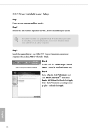
... for AMD driver updates. AMD Catalyst Control Center Step 4 Double-click the AMD Catalyst Control Center icon in your graphics card and click Apply. Select the GPU number according to installation. Please check AMD's website for details. Then select Enable AMD CrossFireX and click Apply. The Catalyst Uninstaller is an optional download. 2.8.2 Driver Installation and Setup Step 1 Power on your computer. English 34 We recommend using this utility to uninstall any VGA drivers installed...
... for AMD driver updates. AMD Catalyst Control Center Step 4 Double-click the AMD Catalyst Control Center icon in your graphics card and click Apply. Select the GPU number according to installation. Please check AMD's website for details. Then select Enable AMD CrossFireX and click Apply. The Catalyst Uninstaller is an optional download. 2.8.2 Driver Installation and Setup Step 1 Power on your computer. English 34 We recommend using this utility to uninstall any VGA drivers installed...
User Manual
Page 49
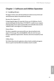
... Utilities Menu The Utilities Menu shows the application software that enhance the motherboard's features. B550 Phantom Gaming 4 Chapter 3 Software and Utilities Operation 3.1 Installing Drivers The Support CD that comes with the motherboard contains necessary drivers and useful utilities that the motherboard supports. Drivers Menu The drivers compatible to install those required drivers. If the Main Menu does not appear automatically, locate and double click on a specific item then follow the order from top to bottom to your system will be auto...
... Utilities Menu The Utilities Menu shows the application software that enhance the motherboard's features. B550 Phantom Gaming 4 Chapter 3 Software and Utilities Operation 3.1 Installing Drivers The Support CD that comes with the motherboard contains necessary drivers and useful utilities that the motherboard supports. Drivers Menu The drivers compatible to install those required drivers. If the Main Menu does not appear automatically, locate and double click on a specific item then follow the order from top to bottom to your system will be auto...

User Manual
Page 66
... which may be set to [Manual], the multiplier and voltage will be combined with a custom CPU core 60 English Because the UEFI software is depending on user selection. Please install an operating system and the drivers required before overclocking, or else your screen. Overclocking is not supported if the monitor is set based on the CPU's capability. CPU Frequency and Voltage(VID) Change If this item is connected via the onboard D-Bus/VGA connector. Overclock Mode(Bus Speed) Select the overclock mode.
... which may be set to [Manual], the multiplier and voltage will be combined with a custom CPU core 60 English Because the UEFI software is depending on user selection. Please install an operating system and the drivers required before overclocking, or else your screen. Overclocking is not supported if the monitor is set based on the CPU's capability. CPU Frequency and Voltage(VID) Change If this item is connected via the onboard D-Bus/VGA connector. Overclock Mode(Bus Speed) Select the overclock mode.

User Manual
Page 67
... your DRAM Voltage. CCX1 Frequency (MHz) Use this item to adjust CCX1 Frequency. CLD0 VDDG IOD Voltage Control AMD Overclocking Setup VDDG IOD represents voltage for idle cores (e.g. VDDG can approach but not exceed your DRAM Voltage (VDDIO_Mem). CCX1 Frequency (MHz) Use this item to adjust CCX1 Frequency. As a result, VDDP voltage in mV to adjust CCX0 Frequency. B550 Phantom Gaming 4 frequency. CCD1 CCX0 Frequency (MHz) Use this item to support memory and Infinity Fabric overclocking. cc6 sleep) remain...
... your DRAM Voltage. CCX1 Frequency (MHz) Use this item to adjust CCX1 Frequency. CLD0 VDDG IOD Voltage Control AMD Overclocking Setup VDDG IOD represents voltage for idle cores (e.g. VDDG can approach but not exceed your DRAM Voltage (VDDIO_Mem). CCX1 Frequency (MHz) Use this item to adjust CCX1 Frequency. As a result, VDDP voltage in mV to adjust CCX0 Frequency. B550 Phantom Gaming 4 frequency. CCD1 CCX0 Frequency (MHz) Use this item to support memory and Infinity Fabric overclocking. cc6 sleep) remain...


