
User Manual
Page 4
...1 1.1 Package Contents 1 1.2 Specifications 2 1.3 Motherboard Layout 7 1.4 I/O Panel 9 1.5 Graphics Card Holder 11 Chapter 2 Installation 12 2.1 Installing the CPU 13 2.2 Installing the CPU Fan and Heatsink 15 2.3 Installing Memory Modules (DIMM) 23 2.4 Expansion Slots (PCI Express Slots) 26 2.5 Jumpers Setup 28 2.6 Onboard Headers and Connectors 29 2.7 Post Status Checker 35 2.8 CrossFireXTM and Quad CrossFireXTM Operation Guide 36 2.8.1 Installing Two CrossFireXTM-Ready Graphics Cards 36 2.9 M.2 2230 WiFi/BT PCIe WiFi module Installation Guide (M2_3) 39 2.10...
...1 1.1 Package Contents 1 1.2 Specifications 2 1.3 Motherboard Layout 7 1.4 I/O Panel 9 1.5 Graphics Card Holder 11 Chapter 2 Installation 12 2.1 Installing the CPU 13 2.2 Installing the CPU Fan and Heatsink 15 2.3 Installing Memory Modules (DIMM) 23 2.4 Expansion Slots (PCI Express Slots) 26 2.5 Jumpers Setup 28 2.6 Onboard Headers and Connectors 29 2.7 Post Status Checker 35 2.8 CrossFireXTM and Quad CrossFireXTM Operation Guide 36 2.8.1 Installing Two CrossFireXTM-Ready Graphics Cards 36 2.9 M.2 2230 WiFi/BT PCIe WiFi module Installation Guide (M2_3) 39 2.10...
User Manual
Page 7
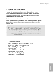
... latest VGA cards and CPU support list on ASRock's website without notice. In case any modifications of the motherboard and step-by-step installation guides. Chapter 3 contains the operation guide of the BIOS setup. ASRock website http://www.asrock.com. 1.1 Package Contents • ASRock B550 PG Riptide Motherboard (ATX Form Factor) • ASRock B550 PG Riptide Quick Installation Guide • ASRock B550 PG Riptide Support CD • 1 x I/O Panel Shield • 2 x Serial ATA (SATA) Data Cables (Optional) • 1 x Graphics Card Holder (Optional) • 3 x Screws for M.2 Sockets...
... latest VGA cards and CPU support list on ASRock's website without notice. In case any modifications of the motherboard and step-by-step installation guides. Chapter 3 contains the operation guide of the BIOS setup. ASRock website http://www.asrock.com. 1.1 Package Contents • ASRock B550 PG Riptide Motherboard (ATX Form Factor) • ASRock B550 PG Riptide Quick Installation Guide • ASRock B550 PG Riptide Support CD • 1 x I/O Panel Shield • 2 x Serial ATA (SATA) Data Cables (Optional) • 1 x Graphics Card Holder (Optional) • 3 x Screws for M.2 Sockets...

User Manual
Page 9
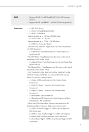
... (High Bit Rate Audio) with HDMI 2.1 Port (Compliant HDMI monitor is occupied, PCIE3 will downgrade to x2 mode. * Supports NVMe SSD as boot disks • 1 x PCI Express 3.0 x1 Slot • Supports AMD Quad CrossFireXTM and CrossFireXTM • 15μ Gold Contact in VGA PCIe Slot (PCIE1) • 1 x M.2 Socket (Key E), supports type 2230 WiFi/BT PCIe WiFi module Graphics • Integrated AMD RadeonTM Vega Series Graphics in DIMM Slots Expansion Slot AMD Ryzen series CPUs (Vermeer and Matisse) • 3 x PCI Express x16 Slots (PCIE1: Gen4x16 mode; Max Shared memory supports...
... (High Bit Rate Audio) with HDMI 2.1 Port (Compliant HDMI monitor is occupied, PCIE3 will downgrade to x2 mode. * Supports NVMe SSD as boot disks • 1 x PCI Express 3.0 x1 Slot • Supports AMD Quad CrossFireXTM and CrossFireXTM • 15μ Gold Contact in VGA PCIe Slot (PCIE1) • 1 x M.2 Socket (Key E), supports type 2230 WiFi/BT PCIe WiFi module Graphics • Integrated AMD RadeonTM Vega Series Graphics in DIMM Slots Expansion Slot AMD Ryzen series CPUs (Vermeer and Matisse) • 3 x PCI Express x16 Slots (PCIE1: Gen4x16 mode; Max Shared memory supports...
User Manual
Page 11
B550 PG Riptide RAID • Supports RAID 0, RAID 1 and RAID 10 for SATA storage devices • Supports RAID 0 and RAID 1 for M.2 NVMe storage devices Connector • 1 x SPI TPM Header • 1 x Power LED and Speaker Header • 2 x RGB LED Headers * Support in total up to 12V/3A, 36W LED Strip • 2 x Addressable LED Headers * Support in total up to 5V/3A, 15W LED Strip • 1 x CPU Fan Connector (4-pin) * The CPU Fan Connector supports the CPU fan of maximum 1A (12W) fan power. • 1 x CPU/Water Pump Fan Connector (4-pin) (Smart Fan Speed Control) * The CPU/Water ...
B550 PG Riptide RAID • Supports RAID 0, RAID 1 and RAID 10 for SATA storage devices • Supports RAID 0 and RAID 1 for M.2 NVMe storage devices Connector • 1 x SPI TPM Header • 1 x Power LED and Speaker Header • 2 x RGB LED Headers * Support in total up to 12V/3A, 36W LED Strip • 2 x Addressable LED Headers * Support in total up to 5V/3A, 15W LED Strip • 1 x CPU Fan Connector (4-pin) * The CPU Fan Connector supports the CPU fan of maximum 1A (12W) fan power. • 1 x CPU/Water Pump Fan Connector (4-pin) (Smart Fan Speed Control) * The CPU/Water ...

User Manual
Page 12
... 6 BIOS Feature Hardware Monitor OS Certifications • AMI UEFI Legal BIOS with overclocking, including adjusting the setting in the BIOS, applying Untied Overclocking Technology, or using third-party overclocking tools. We are not responsible for possible damage caused by CPU temperature): CPU, CPU/Water Pump, Chassis/Water Pump Fans • Fan Multi-Speed Control: CPU, CPU/Water Pump, Chassis/ Water Pump Fans • Voltage monitoring: +12V, +5V, +3.3V, CPU Vcore, CPU VDDCR_SOC, DRAM, CPU VDD 1.8V • Microsoft® Windows®...
... 6 BIOS Feature Hardware Monitor OS Certifications • AMI UEFI Legal BIOS with overclocking, including adjusting the setting in the BIOS, applying Untied Overclocking Technology, or using third-party overclocking tools. We are not responsible for possible damage caused by CPU temperature): CPU, CPU/Water Pump, Chassis/Water Pump Fans • Fan Multi-Speed Control: CPU, CPU/Water Pump, Chassis/ Water Pump Fans • Voltage monitoring: +12V, +5V, +3.3V, CPU Vcore, CPU VDDCR_SOC, DRAM, CPU VDD 1.8V • Microsoft® Windows®...

User Manual
Page 13
1.3 Motherboard Layout 1 2 HDMI1 USB 2.0 T: USB_1 B: USB_2 USB 3.2 Gen1 T: USB1 B: USB2 USB 3.2 Gen2 T: USB31_TA_1 B: USB31_TC_1 ATX12V1 ATX12V2 B550 PG Riptide 3 4 56 7 8 1 ADDR_LED2 CPU_FAN1 CHA_FAN4 CHA_FAN5 /WP /WP 1 9 RGB_LED2 10 ATXPWR1 B550 PG RIPTIDE DDR4_A1 (64 bit, 288-pin module) DDR4_A2 (64 bit, 288-pin module) DDR4_B1 (64 bit, 288-pin module) DDR4_B2 (64 bit, 288-pin module) SOCKET AM4 PS2 Keyboard /Mouse USB 3.2 Gen1 T: USB_3 B: USB_4 USB 3.2 Gen1 Top: T: USB3_5 RJ-45 B: USB3_6 Top: Central...
1.3 Motherboard Layout 1 2 HDMI1 USB 2.0 T: USB_1 B: USB_2 USB 3.2 Gen1 T: USB1 B: USB2 USB 3.2 Gen2 T: USB31_TA_1 B: USB31_TC_1 ATX12V1 ATX12V2 B550 PG Riptide 3 4 56 7 8 1 ADDR_LED2 CPU_FAN1 CHA_FAN4 CHA_FAN5 /WP /WP 1 9 RGB_LED2 10 ATXPWR1 B550 PG RIPTIDE DDR4_A1 (64 bit, 288-pin module) DDR4_A2 (64 bit, 288-pin module) DDR4_B1 (64 bit, 288-pin module) DDR4_B2 (64 bit, 288-pin module) SOCKET AM4 PS2 Keyboard /Mouse USB 3.2 Gen1 T: USB_3 B: USB_4 USB 3.2 Gen1 Top: T: USB3_5 RJ-45 B: USB3_6 Top: Central...

User Manual
Page 14
...) (Lower) 18 Chassis / Waterpump Fan Connector (CHA_FAN3/WP) 19 System Panel Header (PANEL1) 20 Power LED and Speaker Header (SPK_PLED1) 21 Post Status Checker (PSC) 22 Thunderbolt AIC Header (TB1) 23 Clear CMOS Jumper (CLRCMOS1) 24 USB 2.0 Header (USB_7_8) 25 USB 2.0 Header (USB_5_6) 26 USB 2.0 Header (USB_3_4) 27 Chassis/Water Pump Fan Connector (CHA_FAN2/WP) 28 Chassis/Water Pump Fan Connector (CHA_FAN1/WP) 29 Addressable LED Header (ADDR_LED1) 30 RGB LED Header (RGB_LED1) 31 Front Panel Audio Header (HD_AUDIO1) 32 CPU / Waterpump Fan Connector (CPU_FAN2/WP...
...) (Lower) 18 Chassis / Waterpump Fan Connector (CHA_FAN3/WP) 19 System Panel Header (PANEL1) 20 Power LED and Speaker Header (SPK_PLED1) 21 Post Status Checker (PSC) 22 Thunderbolt AIC Header (TB1) 23 Clear CMOS Jumper (CLRCMOS1) 24 USB 2.0 Header (USB_7_8) 25 USB 2.0 Header (USB_5_6) 26 USB 2.0 Header (USB_3_4) 27 Chassis/Water Pump Fan Connector (CHA_FAN2/WP) 28 Chassis/Water Pump Fan Connector (CHA_FAN1/WP) 29 Addressable LED Header (ADDR_LED1) 30 RGB LED Header (RGB_LED1) 31 Front Panel Audio Header (HD_AUDIO1) 32 CPU / Waterpump Fan Connector (CPU_FAN2/WP...

User Manual
Page 17
... Graphics Card Holder to the Graphics Card Holder with 2 screws. Then secure the bracket to the chassis with 1 screw. Step 2 After installing your graphics card, place the bracket in the proper position to make sure that it holds your graphics card in place. English 11 B550 PG Riptide 1.5 Graphics Card Holder Installing the Graphics Card Holder Before installing the Graphics Card Holder , please make sure that your motherboard is properly installed into a PC case...
... Graphics Card Holder to the Graphics Card Holder with 2 screws. Then secure the bracket to the chassis with 1 screw. Step 2 After installing your graphics card, place the bracket in the proper position to make sure that it holds your graphics card in place. English 11 B550 PG Riptide 1.5 Graphics Card Holder Installing the Graphics Card Holder Before installing the Graphics Card Holder , please make sure that your motherboard is properly installed into a PC case...

User Manual
Page 29
... - DR - - 3200 - B550 PG Riptide 2.3 Installing Memory Modules (DIMM) This motherboard provides four 288-pin DDR4 (Double Data Rate 4) DIMM slots, and supports Dual Channel Memory Technology. 1. For dual channel configuration, you install the memory modules on DDR4_A2 and DDR4_B2 first for better DRAM compatibility on 2 DIMMs configuration. It is not allowed to install a DDR, DDR2 or DDR3 memory module into a DDR4 slot; It is unable to install identical (the same brand, speed, size and chip-type) DDR4 DIMM...
... - DR - - 3200 - B550 PG Riptide 2.3 Installing Memory Modules (DIMM) This motherboard provides four 288-pin DDR4 (Double Data Rate 4) DIMM slots, and supports Dual Channel Memory Technology. 1. For dual channel configuration, you install the memory modules on DDR4_A2 and DDR4_B2 first for better DRAM compatibility on 2 DIMMs configuration. It is not allowed to install a DDR, DDR2 or DDR3 memory module into a DDR4 slot; It is unable to install identical (the same brand, speed, size and chip-type) DDR4 DIMM...
User Manual
Page 39
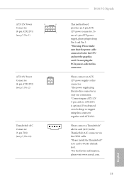
.... 1) ATX 12V Power Connector (4-pin ATX12V2) (see p.7, No. 2) Thunderbolt AIC Connector (5-pin TB1) (see p.7, No. 22) 1 B550 PG Riptide This motherboard provides an 8-pin ATX 12V power connector. Do not plug the PCIe power cable to ATX12V2 is for the CPU and not the graphics card. Please connect an ATX 12V power supply to this connector. *The power supply plug fits into this connector in card (AIC) to the Thunderbolt AIC connector via the GPIO cable. *Please install the Thunderbolt™ AIC card to PCIE3 (default slot...
.... 1) ATX 12V Power Connector (4-pin ATX12V2) (see p.7, No. 2) Thunderbolt AIC Connector (5-pin TB1) (see p.7, No. 22) 1 B550 PG Riptide This motherboard provides an 8-pin ATX 12V power connector. Do not plug the PCIe power cable to ATX12V2 is for the CPU and not the graphics card. Please connect an ATX 12V power supply to this connector. *The power supply plug fits into this connector in card (AIC) to the Thunderbolt AIC connector via the GPIO cable. *Please install the Thunderbolt™ AIC card to PCIE3 (default slot...

User Manual
Page 42
... identical PCI Express x16 graphics cards. 1. CrossFire Bridge Step 2 Connect two graphics cards by installing a CrossFire Bridge on the CrossFire Bridge Interconnects on the slots. Download the drivers from the AMD's website: www.amd.com 3. 2.8 CrossFireXTM and Quad CrossFireXTM Operation Guide This motherboard supports CrossFireXTM and Quad CrossFireXTM that allows you purchase, not bundled with a 16-pipe card, both cards will operate as 12-pipe cards while in CrossFireXTM mode...
... identical PCI Express x16 graphics cards. 1. CrossFire Bridge Step 2 Connect two graphics cards by installing a CrossFire Bridge on the CrossFire Bridge Interconnects on the slots. Download the drivers from the AMD's website: www.amd.com 3. 2.8 CrossFireXTM and Quad CrossFireXTM Operation Guide This motherboard supports CrossFireXTM and Quad CrossFireXTM that allows you purchase, not bundled with a 16-pipe card, both cards will operate as 12-pipe cards while in CrossFireXTM mode...

User Manual
Page 44
... AMD driver updates. AMD Catalyst Control Center Step 4 Double-click the AMD Catalyst Control Center icon in your graphics card and click Apply. We recommend using this utility to uninstall any VGA drivers installed in the Windows® system tray. English 38 Step 5 In the left pane, click Performance and then AMD CrossFireXTM. Step 3 Install the required drivers and CATALYST Control Center then restart your computer and boot into OS. 2.8.2 Driver Installation...
... AMD driver updates. AMD Catalyst Control Center Step 4 Double-click the AMD Catalyst Control Center icon in your graphics card and click Apply. We recommend using this utility to uninstall any VGA drivers installed in the Windows® system tray. English 38 Step 5 In the left pane, click Performance and then AMD CrossFireXTM. Step 3 Install the required drivers and CATALYST Control Center then restart your computer and boot into OS. 2.8.2 Driver Installation...

User Manual
Page 54
... auto-detected and listed on a specific item then follow the order from top to bottom to display the menu. Please click Install All or follow the installation wizard to install it. 48 English Therefore, the drivers you install can work properly. If the Main Menu does not appear automatically, locate and double click on the file "ASRSETUP.EXE" in your computer. Chapter 3 Software and Utilities Operation 3.1 Installing Drivers The Support...
... auto-detected and listed on a specific item then follow the order from top to bottom to display the menu. Please click Install All or follow the installation wizard to install it. 48 English Therefore, the drivers you install can work properly. If the Main Menu does not appear automatically, locate and double click on the file "ASRSETUP.EXE" in your computer. Chapter 3 Software and Utilities Operation 3.1 Installing Drivers The Support...
User Manual
Page 71
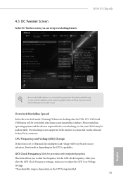
... supported if the monitor is set to [Manual], the multiplier and voltage will be overcloked which may cause instability or failure. CPU Frequency and Voltage(VID) Change If this item is connected via the onboard D-Bus/VGA connector. Warning! When overclocking also the PCIe, PCI, SATA and USB busses will be undetectable. GFX Clock Frequency (Only for processor with integrated graphics) This item allows you can set based on your screen. After you alter the GFX Clock Frequency settings...
... supported if the monitor is set to [Manual], the multiplier and voltage will be overcloked which may cause instability or failure. CPU Frequency and Voltage(VID) Change If this item is connected via the onboard D-Bus/VGA connector. Warning! When overclocking also the PCIe, PCI, SATA and USB busses will be undetectable. GFX Clock Frequency (Only for processor with integrated graphics) This item allows you can set based on your screen. After you alter the GFX Clock Frequency settings...

User Manual
Page 72
... motherboard will be enabled to be overcloked which may be undetectable. When overclocking also the PCIe, PCI, SATA and USB busses will detect the memory module(s) inserted and assign the appropriate frequency automatically. 66 English DRAM Information Browse the serial presence detect (SPD) for the DDR4 bus signaling (PHY), and it is connected via the onboard D-Bus/VGA connector. GFX Core Voltage (Only for processor with integrated graphics. As a result, VDDP voltage...
... motherboard will be enabled to be overcloked which may be undetectable. When overclocking also the PCIe, PCI, SATA and USB busses will detect the memory module(s) inserted and assign the appropriate frequency automatically. 66 English DRAM Information Browse the serial presence detect (SPD) for the DDR4 bus signaling (PHY), and it is connected via the onboard D-Bus/VGA connector. GFX Core Voltage (Only for processor with integrated graphics. As a result, VDDP voltage...

User Manual
Page 76
... AMD-V. AMD fTPM Switch Use this to enable or disable the generation of ACPI_PPC, _PSS, and _PCT objects. 4.4.1 CPU Configuration PSS Support Use this to enable or disable AMD CPU fTPM. 70 English Coniguration options: [Enabled] and [Disabled]. Warning: S3 is not supported on systems where SMT is needed after selecting [Auto]. NX Mode Use this is [Enabled]. To re-enable SMT, a power cycle is disabled. SVM Mode When this to disable symmetric multithreading. The default value is set...
... AMD-V. AMD fTPM Switch Use this to enable or disable the generation of ACPI_PPC, _PSS, and _PCT objects. 4.4.1 CPU Configuration PSS Support Use this to enable or disable AMD CPU fTPM. 70 English Coniguration options: [Enabled] and [Disabled]. Warning: S3 is not supported on systems where SMT is needed after selecting [Auto]. NX Mode Use this is [Enabled]. To re-enable SMT, a power cycle is disabled. SVM Mode When this to disable symmetric multithreading. The default value is set...

User Manual
Page 79
If [Power On] is selected, the power will start to Auto.. 73 English B550 PG Riptide Restore on AC/Power Loss Select the power state after a power failure. Onboard LAN Enable or disable the onboard network interface controller PS2 Y-Cable Enable the PS2 Y-Cable or set this option to boot up when the power recovers. If [Power Off] is selected, the system will remain off when the power recovers.
If [Power On] is selected, the power will start to Auto.. 73 English B550 PG Riptide Restore on AC/Power Loss Select the power state after a power failure. Onboard LAN Enable or disable the onboard network interface controller PS2 Y-Cable Enable the PS2 Y-Cable or set this option to boot up when the power recovers. If [Power Off] is selected, the system will remain off when the power recovers.

User Manual
Page 81
4.4.5 ACPI Configuration B550 PG Riptide Suspend to RAM It is recommended to select auto for better system compatibility and stability. We recommend disabling Deep Sleep for ACPI S3 power saving. PCIE Devices Power On Allow the system to be waked up by a PCIE device and enable wake on LAN. USB Power Delivery in Power State S5. 75 English Deep Sleep Configure deep sleep mode for power saving when the computer is enabled, the USB port will provide power to be waked up by your devices even...
4.4.5 ACPI Configuration B550 PG Riptide Suspend to RAM It is recommended to select auto for better system compatibility and stability. We recommend disabling Deep Sleep for ACPI S3 power saving. PCIE Devices Power On Allow the system to be waked up by a PCIE device and enable wake on LAN. USB Power Delivery in Power State S5. 75 English Deep Sleep Configure deep sleep mode for power saving when the computer is enabled, the USB port will provide power to be waked up by your devices even...

RAID Installation Guide
Page 2
... access and storage since it does not provide any HDDs of Independent Disks", which is an instruction for your motherboard. AMD BIOS RAID Installation Guide The BIOS screenshots in parallel, interleaved stacks. Although RAID 0 function can start to use the onboard RAID Option ROM Utility to configure RAID. 1.1 Introduction to RAID The term "RAID" stands for information on the motherboard you make a SATA driver diskette, press [F2] or [Del] to enter BIOS setup to RAID mode by using for "Redundant Array of the RAID 0 Disk...
... access and storage since it does not provide any HDDs of Independent Disks", which is an instruction for your motherboard. AMD BIOS RAID Installation Guide The BIOS screenshots in parallel, interleaved stacks. Although RAID 0 function can start to use the onboard RAID Option ROM Utility to configure RAID. 1.1 Introduction to RAID The term "RAID" stands for information on the motherboard you make a SATA driver diskette, press [F2] or [Del] to enter BIOS setup to RAID mode by using for "Redundant Array of the RAID 0 Disk...

RAID Installation Guide
Page 13
While the system is shown in this point. 13 When the disk selection page shows up during the Windows installation process, please click . Then restart the system. If the system restarts at this picture. Do not try to open the [F11] boot menu again. 1. Please select this point, then please open the boot menu that is booting, please press [F11] to delete or create any partition at this to boot from. It should list the USB drive as a UEFI device. STEP 3: Windows installation Insert the USB drive with Windows 10 installation files.
While the system is shown in this point. 13 When the disk selection page shows up during the Windows installation process, please click . Then restart the system. If the system restarts at this picture. Do not try to open the [F11] boot menu again. 1. Please select this point, then please open the boot menu that is booting, please press [F11] to delete or create any partition at this to boot from. It should list the USB drive as a UEFI device. STEP 3: Windows installation Insert the USB drive with Windows 10 installation files.


