Intel Rapid Storage Guide
Page 1
... be accessed on one or multiple hard drives, users can reduce the power consumption of faster boot times and data reads. Starting with Link Power Management (LPM), which can take advantage of the chipset and Serial ATA (SATA) hard drive. 1 Through AHCI, storage performance is easily restored. When using one or more than one drive, the user can have additional protection against a hard drive failure when the system is configured for desktop and...
... be accessed on one or multiple hard drives, users can reduce the power consumption of faster boot times and data reads. Starting with Link Power Management (LPM), which can take advantage of the chipset and Serial ATA (SATA) hard drive. 1 Through AHCI, storage performance is easily restored. When using one or more than one drive, the user can have additional protection against a hard drive failure when the system is configured for desktop and...
Intel Rapid Storage Guide
Page 12
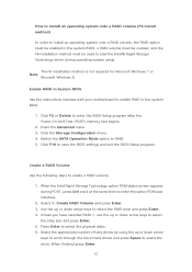
Switch the SATA Operation Mode option to select the physical disks. 6. Select 1: Create RAID Volume and press Enter. 3. Press Enter to RAID. 5. When the Intel Rapid Storage Technology option ROM status screen appears during operating system setup. Click F2 or Delete to enter the option ROM user interface. 2. Click F10 to create a RAID volume. 1. Enetr the Advanced menu. 3. Create a RAID Volume Use the following steps to save the BIOS settings and exit the BIOS Setup program. Unless you...
Switch the SATA Operation Mode option to select the physical disks. 6. Select 1: Create RAID Volume and press Enter. 3. Press Enter to RAID. 5. When the Intel Rapid Storage Technology option ROM status screen appears during operating system setup. Click F2 or Delete to enter the option ROM user interface. 2. Click F10 to create a RAID volume. 1. Enetr the Advanced menu. 3. Create a RAID Volume Use the following steps to save the BIOS settings and exit the BIOS Setup program. Unless you...
Intel Rapid Storage Guide
Page 13
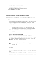
... a floppy disk with a screen asking you see a prompt that says, Press F6 if you have successfully installed the driver and Windows setup should continue. Nothing will temporarily continue loading drivers. Use the Floppy Configuration Utility to install the Intel Rapid Storage Technology driver during text-mode phase). Install the RAID Driver Using the F6 Installation Method Perform the following files: IAAHCI.INF, IAAHCI.CAT, IASTOR.INF, IASTOR.CAT, IASTOR.SYS, and TXTSETUP.OEM. Press Enter...
... a floppy disk with a screen asking you see a prompt that says, Press F6 if you have successfully installed the driver and Windows setup should continue. Nothing will temporarily continue loading drivers. Use the Floppy Configuration Utility to install the Intel Rapid Storage Technology driver during text-mode phase). Install the RAID Driver Using the F6 Installation Method Perform the following files: IAAHCI.INF, IAAHCI.CAT, IASTOR.INF, IASTOR.CAT, IASTOR.SYS, and TXTSETUP.OEM. Press Enter...
Intel Rapid Storage Guide
Page 16
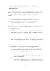
....OEM. You will then be used to load the Intel® Rapid Storage Technology driver during operating system installation. Press S to Specify Additional Device. 3. Setup will happen immediately after pressing F6. You can use the Floppy Configuration Utility to create a floppy disk with a screen asking you to load support for mass storage device(s). 2. Note If you do not need to install a third party SCSI or RAID driver. Press F6 when you see...
....OEM. You will then be used to load the Intel® Rapid Storage Technology driver during operating system installation. Press S to Specify Additional Device. 3. Setup will happen immediately after pressing F6. You can use the Floppy Configuration Utility to create a floppy disk with a screen asking you to load support for mass storage device(s). 2. Note If you do not need to install a third party SCSI or RAID driver. Press F6 when you see...
RAID Installation Guide
Page 7
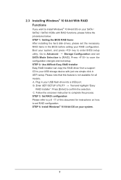
.... Plug in UEFI setup. Press [Enter] to your system, and press key to save the configuration changes and exit setup. STEP 2: Use ASRock Easy RAID Installer Easy RAID Installer can copy the RAID driver from a support CD to confirm the selection C. Boot your USB storage device with RAID functions, please follow the procedures below. Please note that this document for all models A. Press to enter BIOS setup utility. Enter UEFI SETUP UTILITY Tool and highlight "Easy RAID Installer". STEP 1: Setting the BIOS RAID Items After installing the hard disk drives...
.... Plug in UEFI setup. Press [Enter] to your system, and press key to save the configuration changes and exit setup. STEP 2: Use ASRock Easy RAID Installer Easy RAID Installer can copy the RAID driver from a support CD to confirm the selection C. Boot your USB storage device with RAID functions, please follow the procedures below. Please note that this document for all models A. Press to enter BIOS setup utility. Enter UEFI SETUP UTILITY Tool and highlight "Easy RAID Installer". STEP 1: Setting the BIOS RAID Items After installing the hard disk drives...
RAID Installation Guide
Page 19
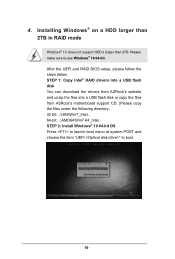
After the UEFI and RAID BIOS setup, please follow the steps below. STEP 1: Copy Intel® RAID drivers into a USB flash disk You can download the drivers from ASRock's website and unzip the files into a USB flash disk or copy the files from ASRock's motherboard support CD. (Please copy the files under the following directory: 32 bit: ..\i386\Win7_Intel.. 64-bit: ..\AMD64\Win7-64_Intel.. STEP 2: Install Windows® 10 64-bit OS Press to launch boot menu at system...
After the UEFI and RAID BIOS setup, please follow the steps below. STEP 1: Copy Intel® RAID drivers into a USB flash disk You can download the drivers from ASRock's website and unzip the files into a USB flash disk or copy the files from ASRock's motherboard support CD. (Please copy the files under the following directory: 32 bit: ..\i386\Win7_Intel.. 64-bit: ..\AMD64\Win7-64_Intel.. STEP 2: Install Windows® 10 64-bit OS Press to launch boot menu at system...
User Manual
Page 4
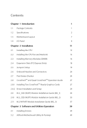
... 1 1.1 Package Contents 1 1.2 Specifications 2 1.3 Motherboard Layout 7 1.4 I/O Panel 9 Chapter 2 Installation 11 2.1 Installing the CPU 12 2.2 Installing the CPU Fan and Heatsink 15 2.3 Installing Memory Modules (DIMM) 16 2.4 Expansion Slots (PCI Express Slots) 18 2.5 Jumpers Setup 19 2.6 Onboard Headers and Connectors 20 2.7 Post Status Checker 26 2.8 CrossFireXTM and Quad CrossFireXTM Operation Guide 27 2.8.1 Installing Two CrossFireXTM-Ready Graphics Cards 27 2.8.2 Driver Installation and Setup 29 2.9 M.2_SSD (NGFF) Module Installation Guide (M2_1) 30 2.10...
... 1 1.1 Package Contents 1 1.2 Specifications 2 1.3 Motherboard Layout 7 1.4 I/O Panel 9 Chapter 2 Installation 11 2.1 Installing the CPU 12 2.2 Installing the CPU Fan and Heatsink 15 2.3 Installing Memory Modules (DIMM) 16 2.4 Expansion Slots (PCI Express Slots) 18 2.5 Jumpers Setup 19 2.6 Onboard Headers and Connectors 20 2.7 Post Status Checker 26 2.8 CrossFireXTM and Quad CrossFireXTM Operation Guide 27 2.8.1 Installing Two CrossFireXTM-Ready Graphics Cards 27 2.8.2 Driver Installation and Setup 29 2.9 M.2_SSD (NGFF) Module Installation Guide (M2_1) 30 2.10...
User Manual
Page 7
...; ASRock B460 Steel Legend Support CD • 2 x Serial ATA (SATA) Data Cables (Optional) • 3 x Screws for M.2 Sockets (Optional) • 2 x Standoffs for purchasing ASRock B460 Steel Legend motherboard, a reliable motherboard produced under ASRock's consistently stringent quality control. Chapter 4 contains the configuration guide of the software and utilities. If you require technical support related to change without further notice. B460 Steel Legend Chapter 1 Introduction Thank you are using. Because the motherboard specifications and the BIOS software might be updated, the...
...; ASRock B460 Steel Legend Support CD • 2 x Serial ATA (SATA) Data Cables (Optional) • 3 x Screws for M.2 Sockets (Optional) • 2 x Standoffs for purchasing ASRock B460 Steel Legend motherboard, a reliable motherboard produced under ASRock's consistently stringent quality control. Chapter 4 contains the configuration guide of the software and utilities. If you require technical support related to change without further notice. B460 Steel Legend Chapter 1 Introduction Thank you are using. Because the motherboard specifications and the BIOS software might be updated, the...
User Manual
Page 14
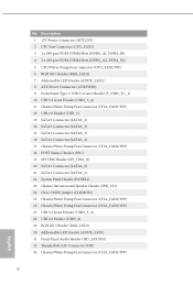
...-pin DDR4 DIMM Slots (DDR4_A1, DDR4_B1) 4 2 x 288-pin DDR4 DIMM Slots (DDR4_A2, DDR4_B2) 5 CPU/Water Pump Fan Connector (CPU_FAN2/WP) 6 RGB LED Header (RGB_LED2) 7 Addressable LED Header (ADDR_LED2) 8 ATX Power Connector (ATXPWR1) 9 Front Panel Type C USB 3.2 Gen1 Header (F_USB3_TC_1) 10 USB 3.2 Gen1 Header (USB3_5_6) 11 Chassis/Water Pump Fan Connector (CHA_FAN5/WP) 12 USB 2.0 Header (USB_5) 13 SATA3 Connector (SATA3_2) 14 SATA3 Connector (SATA3_3) 15 SATA3 Connector (SATA3_5) 16 SATA3 Connector (SATA3_4) 17 Chassis/Water Pump Fan Connector (CHA_FAN4/WP) 18 POST Status...
...-pin DDR4 DIMM Slots (DDR4_A1, DDR4_B1) 4 2 x 288-pin DDR4 DIMM Slots (DDR4_A2, DDR4_B2) 5 CPU/Water Pump Fan Connector (CPU_FAN2/WP) 6 RGB LED Header (RGB_LED2) 7 Addressable LED Header (ADDR_LED2) 8 ATX Power Connector (ATXPWR1) 9 Front Panel Type C USB 3.2 Gen1 Header (F_USB3_TC_1) 10 USB 3.2 Gen1 Header (USB3_5_6) 11 Chassis/Water Pump Fan Connector (CHA_FAN5/WP) 12 USB 2.0 Header (USB_5) 13 SATA3 Connector (SATA3_2) 14 SATA3 Connector (SATA3_3) 15 SATA3 Connector (SATA3_5) 16 SATA3 Connector (SATA3_4) 17 Chassis/Water Pump Fan Connector (CHA_FAN4/WP) 18 POST Status...
User Manual
Page 25
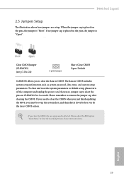
... default setup, please turn off the computer and unplug the power cord, then use a jumper cap to short the pins on the pins, the jumper is "Short". If you to clear the CMOS when you just finish updating the BIOS, you must boot up the system first, and then shut it down before you do the clear-CMOS action. Please remember to clear the record of previous chassis intrusion status. B460 Steel Legend 2.5 Jumpers Setup...
... default setup, please turn off the computer and unplug the power cord, then use a jumper cap to short the pins on the pins, the jumper is "Short". If you to clear the CMOS when you just finish updating the BIOS, you must boot up the system first, and then shut it down before you do the clear-CMOS action. Please remember to clear the record of previous chassis intrusion status. B460 Steel Legend 2.5 Jumpers Setup...
User Manual
Page 29
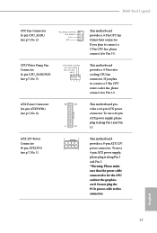
... connect it along Pin 1 and Pin 5. *Warning: Please make sure that the power cable connected is for the CPU and not the graphics card. To use a 20-pin ATX power supply, please plug it to Pin 1-3. Do not plug the PCIe power cable to connect a 3-Pin CPU fan, please connect it along Pin 1 and Pin 13. ATX Power Connector (24-pin ATXPWR1) (see p.7, No. 1) 8 5 This motherboard provides a 8-pin ATX 12V 4 1 power connector. To use a 4-pin ATX power supply, please plug it to Pin 1-3. If you plan to this connector. B460 Steel Legend CPU Fan Connector (4-pin...
... connect it along Pin 1 and Pin 5. *Warning: Please make sure that the power cable connected is for the CPU and not the graphics card. To use a 20-pin ATX power supply, please plug it to Pin 1-3. Do not plug the PCIe power cable to connect a 3-Pin CPU fan, please connect it along Pin 1 and Pin 13. ATX Power Connector (24-pin ATXPWR1) (see p.7, No. 1) 8 5 This motherboard provides a 8-pin ATX 12V 4 1 power connector. To use a 4-pin ATX power supply, please plug it to Pin 1-3. If you plan to this connector. B460 Steel Legend CPU Fan Connector (4-pin...
User Manual
Page 33
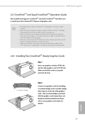
...-pipe card, both cards will operate as 12-pipe cards while in CrossFireXTM mode. 5. Please refer to your graphics card vendor for detailed installation guide. 2.8.1 Installing Two CrossFireXTM-Ready Graphics Cards Step 1 Insert one graphics card into PCIE1 slot and the other graphics card to AMD graphics card manuals for details.) English 27 You should only use a AMD certified PSU. Please refer to enable CrossFireXTM. B460 Steel Legend 2.8 CrossFireXTM and Quad CrossFireXTM Operation Guide This motherboard supports CrossFireXTM and...
...-pipe card, both cards will operate as 12-pipe cards while in CrossFireXTM mode. 5. Please refer to your graphics card vendor for detailed installation guide. 2.8.1 Installing Two CrossFireXTM-Ready Graphics Cards Step 1 Insert one graphics card into PCIE1 slot and the other graphics card to AMD graphics card manuals for details.) English 27 You should only use a AMD certified PSU. Please refer to enable CrossFireXTM. B460 Steel Legend 2.8 CrossFireXTM and Quad CrossFireXTM Operation Guide This motherboard supports CrossFireXTM and...
User Manual
Page 35
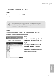
.... Please check AMD's website for AMD driver updates. Then select Enable AMD CrossFireX and click Apply. AMD Catalyst Control Center Step 4 Double-click the AMD Catalyst Control Center icon in your graphics card and click Apply. The Catalyst Uninstaller is an optional download. We recommend using this utility to uninstall any VGA drivers installed in the Windows® system tray. Step 2 Remove the AMD drivers if you have any previously installed Catalyst drivers prior to...
.... Please check AMD's website for AMD driver updates. Then select Enable AMD CrossFireX and click Apply. AMD Catalyst Control Center Step 4 Double-click the AMD Catalyst Control Center icon in your graphics card and click Apply. The Catalyst Uninstaller is an optional download. We recommend using this utility to uninstall any VGA drivers installed in the Windows® system tray. Step 2 Remove the AMD drivers if you have any previously installed Catalyst drivers prior to...
User Manual
Page 45
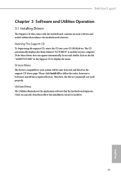
Therefore, the drivers you install can work properly. Utilities Menu The Utilities Menu shows the application software that enhance the motherboard's features. Click on a specific item then follow the order from top to bottom to display the menu. B460 Steel Legend Chapter 3 Software and Utilities Operation 3.1 Installing Drivers The Support CD that comes with the motherboard contains necessary drivers and useful utilities that the motherboard supports. Drivers Menu The drivers compatible to install it. 39 English Please click Install All or follow the...
Therefore, the drivers you install can work properly. Utilities Menu The Utilities Menu shows the application software that enhance the motherboard's features. Click on a specific item then follow the order from top to bottom to display the menu. B460 Steel Legend Chapter 3 Software and Utilities Operation 3.1 Installing Drivers The Support CD that comes with the motherboard contains necessary drivers and useful utilities that the motherboard supports. Drivers Menu The drivers compatible to install it. 39 English Please click Install All or follow the...
User Manual
Page 75
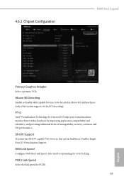
... SR-IOV capable PCIe Devices, this option Enables or Disables Single Root IO Virtualization Support. DMI Link Speed Configure DMI Slot Link Speed. 4.6.2 Chipset Configuration B460 Steel Legend Primary Graphics Adapter Select a primary VGA. Above 4G Decoding Enable or disable 64bit capable Devices to be decoded in Above 4G Address Space (only if the system supports 64 bit PCI decoding). Auto mode is optimizing for Directed I/O helps your virtual machine monitor better utilize hardware by improving application compatibility and reliability...
... SR-IOV capable PCIe Devices, this option Enables or Disables Single Root IO Virtualization Support. DMI Link Speed Configure DMI Slot Link Speed. 4.6.2 Chipset Configuration B460 Steel Legend Primary Graphics Adapter Select a primary VGA. Above 4G Decoding Enable or disable 64bit capable Devices to be decoded in Above 4G Address Space (only if the system supports 64 bit PCI decoding). Auto mode is optimizing for Directed I/O helps your virtual machine monitor better utilize hardware by improving application compatibility and reliability...

User Manual
Page 76
... Audio Enable/disable onboard HD audio. PCH PCIE ASPM Support This option enables/disables the ASPM support for enhanced PCI Express power saving in OS. IGPU Multi-Monitor Select disable to the integrated graphics processor when the system boots up. PCIE4 Link Speed Select the link speed for PCIE4. DMI ASPM Support This option enables/disables the control of ASPM on CPU side of memory that is allocated to disable the integrated graphics when an external graphics card is installed. 70 English Share Memory Configure...
... Audio Enable/disable onboard HD audio. PCH PCIE ASPM Support This option enables/disables the ASPM support for enhanced PCI Express power saving in OS. IGPU Multi-Monitor Select disable to the integrated graphics processor when the system boots up. PCIE4 Link Speed Select the link speed for PCIE4. DMI ASPM Support This option enables/disables the control of ASPM on CPU side of memory that is allocated to disable the integrated graphics when an external graphics card is installed. 70 English Share Memory Configure...
User Manual
Page 79
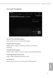
Security Level This item allows you to choose a security level for OSUP. Thunderbolt Boot Support Enabled to allow booting from Usb devices which are present behind Thunderbolt. Thunderbolt Usb Support Enabled to allow booting from Bootable devices which are present behind Thunderbolt. Titan Ridge Workaround for OSUP Enable or disable Titan Ridge Workaround for the Thunderbolt ports. 73 English 4.6.4 Intel® Thunderbolt B460 Steel Legend Discrete Thunderbolt(TM) Support Enable or disable the Discrete Thunderbolt(TM) Support.
Security Level This item allows you to choose a security level for OSUP. Thunderbolt Boot Support Enabled to allow booting from Usb devices which are present behind Thunderbolt. Thunderbolt Usb Support Enabled to allow booting from Bootable devices which are present behind Thunderbolt. Titan Ridge Workaround for OSUP Enable or disable Titan Ridge Workaround for the Thunderbolt ports. 73 English 4.6.4 Intel® Thunderbolt B460 Steel Legend Discrete Thunderbolt(TM) Support Enable or disable the Discrete Thunderbolt(TM) Support.
User Manual
Page 84
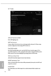
... user data will be permanently destroyed on the SSD and cannot be recovered. After copying the drivers please change the SATA mode to update your PC. 4.7 Tools ASRock Polychrome RGB Select LED lighting color. UEFI Tech Service Contact ASRock Tech Service if you can start installing the operating system in your USB storage device and run Instant Flash to RAID, then you are having trouble with your UEFI. 78 English Please setup network configuration before using UEFI...
... user data will be permanently destroyed on the SSD and cannot be recovered. After copying the drivers please change the SATA mode to update your PC. 4.7 Tools ASRock Polychrome RGB Select LED lighting color. UEFI Tech Service Contact ASRock Tech Service if you can start installing the operating system in your USB storage device and run Instant Flash to RAID, then you are having trouble with your UEFI. 78 English Please setup network configuration before using UEFI...
User Manual
Page 85
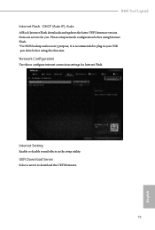
... (Auto IP), Auto ASRock Internet Flash downloads and updates the latest UEFI firmware version from our servers for Internet Flash. Network Configuration Use this function. UEFI Download Server Select a server to configure internet connection settings for you. Internet Setting Enable or disable sound effects in your USB pen drive before using this to download the UEFI firmware. 79 English Please setup network configuration before using Internet Flash. *For BIOS backup and recovery purpose, it is recommended to plug in the setup utility. B460 Steel Legend Internet Flash...
... (Auto IP), Auto ASRock Internet Flash downloads and updates the latest UEFI firmware version from our servers for Internet Flash. Network Configuration Use this function. UEFI Download Server Select a server to configure internet connection settings for you. Internet Setting Enable or disable sound effects in your USB pen drive before using this to download the UEFI firmware. 79 English Please setup network configuration before using Internet Flash. *For BIOS backup and recovery purpose, it is recommended to plug in the setup utility. B460 Steel Legend Internet Flash...
User Manual
Page 90
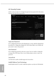
... to enable or disable support for the administrator account. User Password Set or change the password for Secure Boot. Intel(R) Platform Trust Technology Enable/disable Intel PTT in the UEFI Setup Utility. Disable this option to remove the password. Leave it blank and press enter to use discrete TPM Module. 84 English Users are unable to remove the password. 4.9 Security Screen In this section you may also clear the user password. Secure Boot Use this item to change the settings in the UEFI Setup Utility.
... to enable or disable support for the administrator account. User Password Set or change the password for Secure Boot. Intel(R) Platform Trust Technology Enable/disable Intel PTT in the UEFI Setup Utility. Disable this option to remove the password. Leave it blank and press enter to use discrete TPM Module. 84 English Users are unable to remove the password. 4.9 Security Screen In this section you may also clear the user password. Secure Boot Use this item to change the settings in the UEFI Setup Utility.


