
User Manual
Page 4
... Layout 7 1.4 I/O Panel 9 Chapter 2 Installation 11 2.1 Installing the CPU 12 2.2 Installing the CPU Fan and Heatsink 15 2.3 Installing Memory Modules (DIMM) 16 2.4 Expansion Slots (PCI and PCI Express Slots) 18 2.5 Jumpers Setup 19 2.6 Onboard Headers and Connectors 20 2.7 CrossFireXTM and Quad CrossFireXTM Operation Guide 24 2.7.1 Installing Two CrossFireXTM-Ready Graphics Cards 24 2.7.2 Driver Installation and Setup 26 2.8 M.2_SSD (NGFF) Module Installation Guide 27 Chapter 3 Software and Utilities Operation 31 3.1 Installing Drivers 31 3.2 ASRock Live Update...
... Layout 7 1.4 I/O Panel 9 Chapter 2 Installation 11 2.1 Installing the CPU 12 2.2 Installing the CPU Fan and Heatsink 15 2.3 Installing Memory Modules (DIMM) 16 2.4 Expansion Slots (PCI and PCI Express Slots) 18 2.5 Jumpers Setup 19 2.6 Onboard Headers and Connectors 20 2.7 CrossFireXTM and Quad CrossFireXTM Operation Guide 24 2.7.1 Installing Two CrossFireXTM-Ready Graphics Cards 24 2.7.2 Driver Installation and Setup 26 2.8 M.2_SSD (NGFF) Module Installation Guide 27 Chapter 3 Software and Utilities Operation 31 3.1 Installing Drivers 31 3.2 ASRock Live Update...
User Manual
Page 6
... to change without further notice. Because the motherboard specifications and the BIOS software might be available on ASRock's website as well. You may find the latest VGA cards and CPU support list on ASRock's website without notice. Chapter 4 contains the configuration guide of this documentation will be updated, the content of the software and utilities. In case any modifications of the BIOS setup. B250M DASH Chapter 1 Introduction Thank you for M.2 Sockets (Optional) • 1 x I/O Panel Shield...
... to change without further notice. Because the motherboard specifications and the BIOS software might be available on ASRock's website as well. You may find the latest VGA cards and CPU support list on ASRock's website without notice. Chapter 4 contains the configuration guide of this documentation will be updated, the content of the software and utilities. In case any modifications of the BIOS setup. B250M DASH Chapter 1 Introduction Thank you for M.2 Sockets (Optional) • 1 x I/O Panel Shield...

User Manual
Page 7
... Graphics Built-in DIMM Slots Expansion Slot • 2 x PCI Express 3.0 x16 Slots (PCIE1: x16 mode; 1.2 Specifications Platform CPU • Micro ATX Form Factor • Solid Capacitor design • Supports 7th and 6th Generation Intel® CoreTM i7/i5/i3/ Pentium®/Celeron® Processors (Socket 1151) • Digi Power design • 6 Power Phase design • Supports Intel® Turbo Boost 2.0 Technology Chipset • Intel® B250 Memory • Dual Channel DDR4 Memory Technology...
... Graphics Built-in DIMM Slots Expansion Slot • 2 x PCI Express 3.0 x16 Slots (PCIE1: x16 mode; 1.2 Specifications Platform CPU • Micro ATX Form Factor • Solid Capacitor design • Supports 7th and 6th Generation Intel® CoreTM i7/i5/i3/ Pentium®/Celeron® Processors (Socket 1151) • Digi Power design • 6 Power Phase design • Supports Intel® Turbo Boost 2.0 Technology Chipset • Intel® B250 Memory • Dual Channel DDR4 Memory Technology...
User Manual
Page 8
shared memory 1024MB * The size of maximum shared memory may vary from different operating systems. • Four graphics output options: D-Sub, DVI-D, HDMI and DisplayPort 1.2 • Supports Triple Monitor • Supports HDMI with max. resolution up to 1920x1200 @ 60Hz • Supports DisplayPort 1.2 with max. resolution up to 1920x1200 @ 60Hz • Supports D-Sub with max. B250M DASH Audio • Gen9 LP, DX11.3, DX12 • HWAEncode/Decode: VP8, HEVC 8b, VP9...
shared memory 1024MB * The size of maximum shared memory may vary from different operating systems. • Four graphics output options: D-Sub, DVI-D, HDMI and DisplayPort 1.2 • Supports Triple Monitor • Supports HDMI with max. resolution up to 1920x1200 @ 60Hz • Supports DisplayPort 1.2 with max. resolution up to 1920x1200 @ 60Hz • Supports D-Sub with max. B250M DASH Audio • Gen9 LP, DX11.3, DX12 • HWAEncode/Decode: VP8, HEVC 8b, VP9...

User Manual
Page 9
...Sub Port • 1 x DVI-D Port • 1 x HDMI Port • 1 x DisplayPort 1.2 • 2 x USB 2.0 Ports (Supports ESD Protection) • 3 x USB 3.1 Gen1 Type-A Ports (Supports ESD Protection) • 1 x USB 3.1 Gen1 Type-C Port (Supports ESD Protection) • 1 x RJ-45 LAN Port with LED (ACT/LINK LED and SPEED LED) • HD Audio Jacks: Line in / Front Speaker / Microphone Storage • 6 x SATA3 6.0 Gb/s Connectors, support NCQ, AHCI and Hot Plug* * If M2_1 is occupied by a SATA-type M.2 device, SATA3_0 will be disabled. • 1 x Ultra M.2 Socket (M2_1), supports M Key type...
...Sub Port • 1 x DVI-D Port • 1 x HDMI Port • 1 x DisplayPort 1.2 • 2 x USB 2.0 Ports (Supports ESD Protection) • 3 x USB 3.1 Gen1 Type-A Ports (Supports ESD Protection) • 1 x USB 3.1 Gen1 Type-C Port (Supports ESD Protection) • 1 x RJ-45 LAN Port with LED (ACT/LINK LED and SPEED LED) • HD Audio Jacks: Line in / Front Speaker / Microphone Storage • 6 x SATA3 6.0 Gb/s Connectors, support NCQ, AHCI and Hot Plug* * If M2_1 is occupied by a SATA-type M.2 device, SATA3_0 will be disabled. • 1 x Ultra M.2 Socket (M2_1), supports M Key type...

User Manual
Page 10
... 3-pin or 4-pin fan is in use. • 1 x 24 pin ATX Power Connector • 1 x 8 pin 12V Power Connector • 1 x Front Panel Audio Connector • 2 x USB 2.0 Headers (Support 4 USB 2.0 ports) (Supports ESD Protection) • 1 x USB 3.1 Gen1 Header (Supports 2 USB 3.1 Gen1 ports) (Supports ESD Protection) BIOS Feature • AMI UEFI Legal BIOS with multilingual GUI support • ACPI 6.0 Compliant wake up events • SMBIOS 2.7 Support • CPU, GT_CPU, DRAM, PCH 1.0V, VCCIO, VCCSA, VCCST Voltage Multi-adjustment Hardware Monitor • CPU/Chassis temperature sensing...
... 3-pin or 4-pin fan is in use. • 1 x 24 pin ATX Power Connector • 1 x 8 pin 12V Power Connector • 1 x Front Panel Audio Connector • 2 x USB 2.0 Headers (Support 4 USB 2.0 ports) (Supports ESD Protection) • 1 x USB 3.1 Gen1 Header (Supports 2 USB 3.1 Gen1 ports) (Supports ESD Protection) BIOS Feature • AMI UEFI Legal BIOS with multilingual GUI support • ACPI 6.0 Compliant wake up events • SMBIOS 2.7 Support • CPU, GT_CPU, DRAM, PCH 1.0V, VCCIO, VCCSA, VCCST Voltage Multi-adjustment Hardware Monitor • CPU/Chassis temperature sensing...

User Manual
Page 13
... 2 Chassis Fan Connector (CHA_FAN1) 3 CPU Fan Connector (CPU_FAN1) 4 CPU Fan Connector (CPU_FAN2) 5 2 x 288-pin DDR4 DIMM Slots (DDR4_A1, DDR4_B1) 6 2 x 288-pin DDR4 DIMM Slots (DDR4_A2, DDR4_B2) 7 ATX Power Connector (ATXPWR1) 8 USB 3.1 Gen1 Header (USB3_5_6) 9 SATA3 Connector (SATA3_0) 10 SATA3 Connector (SATA3_1) 11 Chassis Fan Connector (CHA_FAN2) 12 SATA3 Connector (SATA3_2) 13 SATA3 Connector (SATA3_3) 14 SATA3 Connector (SATA3_5) 15 SATA3 Connector (SATA3_4) 16 Clear CMOS Jumper (CLRMOS1) 17 Chassis Intrusion and Speaker Header (SPK_CI1) 18 System Panel Header (PANEL1) 19 USB 2.0 Header...
... 2 Chassis Fan Connector (CHA_FAN1) 3 CPU Fan Connector (CPU_FAN1) 4 CPU Fan Connector (CPU_FAN2) 5 2 x 288-pin DDR4 DIMM Slots (DDR4_A1, DDR4_B1) 6 2 x 288-pin DDR4 DIMM Slots (DDR4_A2, DDR4_B2) 7 ATX Power Connector (ATXPWR1) 8 USB 3.1 Gen1 Header (USB3_5_6) 9 SATA3 Connector (SATA3_0) 10 SATA3 Connector (SATA3_1) 11 Chassis Fan Connector (CHA_FAN2) 12 SATA3 Connector (SATA3_2) 13 SATA3 Connector (SATA3_3) 14 SATA3 Connector (SATA3_5) 15 SATA3 Connector (SATA3_4) 16 Clear CMOS Jumper (CLRMOS1) 17 Chassis Intrusion and Speaker Header (SPK_CI1) 18 System Panel Header (PANEL1) 19 USB 2.0 Header...

User Manual
Page 23
PCI slot: The PCI1 slot is used to the motherboard's chassis fan connector (CHA_FAN1 or CHA_FAN2) when using multiple graphics cards. PCIe Slot Configurations Single Graphics Card Two Graphics Cards in CrossFireXTM Mode PCIE1 x16 x16 PCIE3 N/A x4 For a better thermal environment, please connect a chassis fan to install expansion cards that the power supply is switched off or the power cord is unplugged. PCIE2 (PCIe 3.0 x1 slot) is 1 PCI slot and 3 PCI Express slots on M2_1 socket will run at Gen3 x2 (16 Gb/s). Please read the...
PCI slot: The PCI1 slot is used to the motherboard's chassis fan connector (CHA_FAN1 or CHA_FAN2) when using multiple graphics cards. PCIe Slot Configurations Single Graphics Card Two Graphics Cards in CrossFireXTM Mode PCIE1 x16 x16 PCIE3 N/A x4 For a better thermal environment, please connect a chassis fan to install expansion cards that the power supply is switched off or the power cord is unplugged. PCIE2 (PCIe 3.0 x1 slot) is 1 PCI slot and 3 PCI Express slots on M2_1 socket will run at Gen3 x2 (16 Gb/s). Please read the...

User Manual
Page 24
... the password, date, time, and user default profile will be detected. Please adjust the BIOS option "Clear Status" to short pin2 and pin3 on these 2 pins. To clear and reset the system parameters to clear the data in CMOS. B250M DASH 2.5 Jumpers Setup The illustration shows how jumpers are "Short" when a jumper cap is "Short". English 19 If you to default setup, please turn off the computer and unplug the power cord from the power supply. Clear CMOS Jumper...
... the password, date, time, and user default profile will be detected. Please adjust the BIOS option "Clear Status" to short pin2 and pin3 on these 2 pins. To clear and reset the system parameters to clear the data in CMOS. B250M DASH 2.5 Jumpers Setup The illustration shows how jumpers are "Short" when a jumper cap is "Short". English 19 If you to default setup, please turn off the computer and unplug the power cord from the power supply. Clear CMOS Jumper...

User Manual
Page 29
... requires. Download the drivers from the AMD's website: www.amd.com 3. If you pair a 12-pipe CrossFireXTM Edition card with this motherboard. Make sure that the cards are AMD certified. 2. Please refer to the AMD's website for detailed installation guide. 2.7.1 Installing Two CrossFireXTM-Ready Graphics Cards Step 1 Insert one graphics card into PCIE1 slot and the other graphics card to three identical PCI Express x16 graphics cards. 1. CrossFire Bridge Step 2 Connect two graphics cards by installing a CrossFire...
... requires. Download the drivers from the AMD's website: www.amd.com 3. If you pair a 12-pipe CrossFireXTM Edition card with this motherboard. Make sure that the cards are AMD certified. 2. Please refer to the AMD's website for detailed installation guide. 2.7.1 Installing Two CrossFireXTM-Ready Graphics Cards Step 1 Insert one graphics card into PCIE1 slot and the other graphics card to three identical PCI Express x16 graphics cards. 1. CrossFire Bridge Step 2 Connect two graphics cards by installing a CrossFire...
User Manual
Page 31
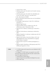
... left pane, click Performance and then AMD CrossFireXTM. AMD Catalyst Control Center Step 4 Double-click the AMD Catalyst Control Center icon in your graphics card and click Apply. 2.7.2 Driver Installation and Setup Step 1 Power on your computer. English 26 The Catalyst Uninstaller is an optional download. Step 3 Install the required drivers and CATALYST Control Center then restart your computer and boot into OS. Select the GPU number...
... left pane, click Performance and then AMD CrossFireXTM. AMD Catalyst Control Center Step 4 Double-click the AMD Catalyst Control Center icon in your graphics card and click Apply. 2.7.2 Driver Installation and Setup Step 1 Power on your computer. English 26 The Catalyst Uninstaller is an optional download. Step 3 Install the required drivers and CATALYST Control Center then restart your computer and boot into OS. Select the GPU number...
User Manual
Page 32
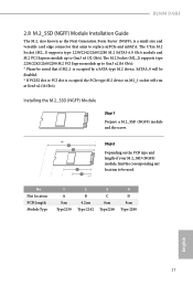
...) supports type 2230/2242/2260/2280 M.2 SATA3 6.0 Gb/s module and M.2 PCI Express module up to Gen3 x2 (16 Gb/s). * Please be used. B250M DASH 2.8 M.2_SSD (NGFF) Module Installation Guide The M.2, also known as the Next Generation Form Factor (NGFF), is a small size and versatile card edge connector that if M2_1 is occupied by a SATA-type M.2 device, SATA3_0 will be disabled. * If PCIE2 slot or PCI slot is occupied, the PCIe-type M.2 device...
...) supports type 2230/2242/2260/2280 M.2 SATA3 6.0 Gb/s module and M.2 PCI Express module up to Gen3 x2 (16 Gb/s). * Please be used. B250M DASH 2.8 M.2_SSD (NGFF) Module Installation Guide The M.2, also known as the Next Generation Form Factor (NGFF), is a small size and versatile card edge connector that if M2_1 is occupied by a SATA-type M.2 device, SATA3_0 will be disabled. * If PCIE2 slot or PCI slot is occupied, the PCIe-type M.2 device...
User Manual
Page 36
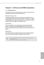
..., locate and double click on the support CD driver page. Therefore, the drivers you install can work properly. "KB2720599": http://support.microsoft.com/kb/2720599/en-us 31 English Drivers Menu The drivers compatible to your system will be auto-detected and listed on the file "ASRSETUP.EXE" in your CD-ROM drive. Please click Install All or follow the installation wizard to install those required drivers. Click on a specific item...
..., locate and double click on the support CD driver page. Therefore, the drivers you install can work properly. "KB2720599": http://support.microsoft.com/kb/2720599/en-us 31 English Drivers Menu The drivers compatible to your system will be auto-detected and listed on the file "ASRSETUP.EXE" in your CD-ROM drive. Please click Install All or follow the installation wizard to install those required drivers. Click on a specific item...

User Manual
Page 43
... to create a new ISO file with the Intel® USB 3.1 Gen1 eXtensible Host Controller (xHCI) drivers packed into the ISO file. Due to that fact that XHCI is an optical disc drive, PS/2 ports and PS/2 Keyboard or mouse on their support for the Enhanced Host Controller Interface (EHCI - 3.3 Enabling USB Ports for Windows® 7 Installation Intel® new processors have removed their motherboard won't work. USB2.0) and only...
... to create a new ISO file with the Intel® USB 3.1 Gen1 eXtensible Host Controller (xHCI) drivers packed into the ISO file. Due to that fact that XHCI is an optical disc drive, PS/2 ports and PS/2 Keyboard or mouse on their support for the Enhanced Host Controller Interface (EHCI - 3.3 Enabling USB Ports for Windows® 7 Installation Intel® new processors have removed their motherboard won't work. USB2.0) and only...

User Manual
Page 46
Because the UEFI software is constantly being updated, the following selections: Main For setting system time/date information OC Tweaker For overclocking configurations Advanced For advanced system configurations Tool Useful tools H/W Monitor Displays current hardware status Security For security settings Boot For configuring boot settings and boot priority Exit Exit the current screen or the UEFI Setup Utility English 41 If you wish to configure your screen. 4.1.1 UEFI Menu Bar The top of the screen has a menu bar...
Because the UEFI software is constantly being updated, the following selections: Main For setting system time/date information OC Tweaker For overclocking configurations Advanced For advanced system configurations Tool Useful tools H/W Monitor Displays current hardware status Security For security settings Boot For configuring boot settings and boot priority Exit Exit the current screen or the UEFI Setup Utility English 41 If you wish to configure your screen. 4.1.1 UEFI Menu Bar The top of the screen has a menu bar...

User Manual
Page 59
... support for all PCH PCIE devices. IOAPIC 24-119 Entries I/O APICs contain a redirection table, which is used to route the interrupts it when a sound card is installed. Select enable to one or more local APICs. Onboard HDMI HD Audio Enable audio for enhanced PCI Express power saving in OS. Enable/disable IOAPIC 24-119 Entries to expand to the integrated graphics processor when the system boots up. Front Panel Enable/disable front panel HD audio. Share Memory Configure...
... support for all PCH PCIE devices. IOAPIC 24-119 Entries I/O APICs contain a redirection table, which is used to route the interrupts it when a sound card is installed. Select enable to one or more local APICs. Onboard HDMI HD Audio Enable audio for enhanced PCI Express power saving in OS. Enable/disable IOAPIC 24-119 Entries to expand to the integrated graphics processor when the system boots up. Front Panel Enable/disable front panel HD audio. Share Memory Configure...

User Manual
Page 63
... waked up by the real time clock alarm. PCIE/PCI Devices Power On Allow the system to be waked up by a PCIE/PCI device and enable wake on LAN. ACPI HEPT Table Enable the High Precision Event Timer for ACPI suspend type S1. USB Keyboard/Remote Power On Allow the system to be waked up by an USB keyboard or remote controller. 58 English Ring-In Power On Allow the system to be waked up by onboard COM port...
... waked up by the real time clock alarm. PCIE/PCI Devices Power On Allow the system to be waked up by a PCIE/PCI device and enable wake on LAN. ACPI HEPT Table Enable the High Precision Event Timer for ACPI suspend type S1. USB Keyboard/Remote Power On Allow the system to be waked up by an USB keyboard or remote controller. 58 English Ring-In Power On Allow the system to be waked up by onboard COM port...

User Manual
Page 67
4.4.8 MCTP Computing Realtek Lan Card DASH Function Enable or disable Realtek Lan card DASH function. PLDM for BIOS Control and Config Enable or disable PLDM for SMBIOS. PLDM for SMBIOS Enable or disable PLDM for BIOS control and Configuration. PLDM for Platform Monitoring Enable or disable PLDM for PLDM for platform monitoring. 62 English MCTP Support Enable or disable MCTP support.
4.4.8 MCTP Computing Realtek Lan Card DASH Function Enable or disable Realtek Lan card DASH function. PLDM for BIOS Control and Config Enable or disable PLDM for SMBIOS. PLDM for SMBIOS Enable or disable PLDM for BIOS control and Configuration. PLDM for Platform Monitoring Enable or disable PLDM for PLDM for platform monitoring. 62 English MCTP Support Enable or disable MCTP support.
User Manual
Page 69
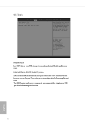
4.5 Tools Instant Flash Save UEFI files in your USB storage device and run Instant Flash to plug in your UEFI. Please setup network configuration before using Internet Flash. *For BIOS backup and recovery purpose, it is recommended to update your USB pen drive before using this function. 64 English DHCP (Auto IP), Auto ASRock Internet Flash downloads and updates the latest UEFI firmware version from our servers for you. Internet Flash -
4.5 Tools Instant Flash Save UEFI files in your USB storage device and run Instant Flash to plug in your UEFI. Please setup network configuration before using Internet Flash. *For BIOS backup and recovery purpose, it is recommended to update your USB pen drive before using this function. 64 English DHCP (Auto IP), Auto ASRock Internet Flash downloads and updates the latest UEFI firmware version from our servers for you. Internet Flash -

User Manual
Page 72
... Technology Enable/disable Intel PTT in the UEFI Setup Utility. Secure Boot Use this item to remove the password. Supervisor Password Set or change the settings in the UEFI Setup Utility. Only the administrator has authority to change the password for the administrator account. Users are unable to change the password for the user account. Leave it blank and press enter to use discrete TPM Module. 67 English You may set or change the supervisor/user password for Windows 8.1 Secure Boot. User Password Set...
... Technology Enable/disable Intel PTT in the UEFI Setup Utility. Secure Boot Use this item to remove the password. Supervisor Password Set or change the settings in the UEFI Setup Utility. Only the administrator has authority to change the password for the administrator account. Users are unable to change the password for the user account. Leave it blank and press enter to use discrete TPM Module. 67 English You may set or change the supervisor/user password for Windows 8.1 Secure Boot. User Password Set...


