
User Manual
Page 4
... Layout 6 1.4 I/O Panel 8 Chapter 2 Installation 10 2.1 Installing the CPU 11 2.2 Installing the CPU Fan and Heatsink 14 2.3 Installing Memory Modules (DIMM) 15 2.4 Expansion Slots (PCI Express Slots) 17 2.5 Jumpers Setup 18 2.6 Onboard Headers and Connectors 19 2.7 CrossFireXTM and Quad CrossFireXTM Operation Guide 23 2.7.1 Installing Two CrossFireXTM-Ready Graphics Cards 23 2.7.2 Driver Installation and Setup 25 2.8 M.2_SSD (NGFF) Module Installation Guide 26 Chapter 3 Software and Utilities Operation 28 3.1 Installing Drivers 28 3.2 ASRock Live Update...
... Layout 6 1.4 I/O Panel 8 Chapter 2 Installation 10 2.1 Installing the CPU 11 2.2 Installing the CPU Fan and Heatsink 14 2.3 Installing Memory Modules (DIMM) 15 2.4 Expansion Slots (PCI Express Slots) 17 2.5 Jumpers Setup 18 2.6 Onboard Headers and Connectors 19 2.7 CrossFireXTM and Quad CrossFireXTM Operation Guide 23 2.7.1 Installing Two CrossFireXTM-Ready Graphics Cards 23 2.7.2 Driver Installation and Setup 25 2.8 M.2_SSD (NGFF) Module Installation Guide 26 Chapter 3 Software and Utilities Operation 28 3.1 Installing Drivers 28 3.2 ASRock Live Update...
User Manual
Page 5
...Enabling USB Ports for Windows® 7 Installation 35 Chapter 4 UEFI SETUP UTILITY 38 4.1 Introduction 38 4.2 EZ Mode 39 4.3 Advanced Mode 40 4.3.1 UEFI Menu Bar 40 4.3.2 Navigation Keys 41 4.4 Main Screen 42 4.5 OC Tweaker Screen 43 4.6 Advanced Screen 51 4.6.1 CPU Configuration 52 4.6.2 Chipset Configuration 54 4.6.3 Storage Configuration 56 4.6.4 Super IO Configuration 57 4.6.5 ACPI Configuration 58 4.6.6 USB Configuration 60 4.6.7 Trusted Computing 61 4.7 Tools 62 4.8 Hardware Health Event Monitoring Screen 65 4.9 Security Screen 67 4.10 Boot Screen...
...Enabling USB Ports for Windows® 7 Installation 35 Chapter 4 UEFI SETUP UTILITY 38 4.1 Introduction 38 4.2 EZ Mode 39 4.3 Advanced Mode 40 4.3.1 UEFI Menu Bar 40 4.3.2 Navigation Keys 41 4.4 Main Screen 42 4.5 OC Tweaker Screen 43 4.6 Advanced Screen 51 4.6.1 CPU Configuration 52 4.6.2 Chipset Configuration 54 4.6.3 Storage Configuration 56 4.6.4 Super IO Configuration 57 4.6.5 ACPI Configuration 58 4.6.6 USB Configuration 60 4.6.7 Trusted Computing 61 4.7 Tools 62 4.8 Hardware Health Event Monitoring Screen 65 4.9 Security Screen 67 4.10 Boot Screen...
User Manual
Page 6
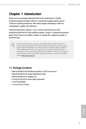
...8226; ASRock B150M Pro4V Quick Installation Guide • ASRock B150M Pro4V Support CD • 2 x Serial ATA (SATA) Data Cables (Optional) • 1 x I/O Panel Shield • 1 x Screw for purchasing ASRock B150M Pro4V motherboard, a reliable motherboard produced under ASRock's consistently stringent quality control. Chapter 3 contains the operation guide of the BIOS setup. You may find the latest VGA cards and CPU support list on ASRock's website without notice. In this motherboard, please visit our website for specific information about the model you for M.2 Socket 1 English...
...8226; ASRock B150M Pro4V Quick Installation Guide • ASRock B150M Pro4V Support CD • 2 x Serial ATA (SATA) Data Cables (Optional) • 1 x I/O Panel Shield • 1 x Screw for purchasing ASRock B150M Pro4V motherboard, a reliable motherboard produced under ASRock's consistently stringent quality control. Chapter 3 contains the operation guide of the BIOS setup. You may find the latest VGA cards and CPU support list on ASRock's website without notice. In this motherboard, please visit our website for specific information about the model you for M.2 Socket 1 English...
User Manual
Page 9
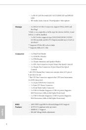
... 4-pin fan is in use. * The CPU Fan Connector supports the CPU fan of maximum 1A (12W) fan power. • 1 x 24 pin ATX Power Connector • 1 x 8 pin 12V Power Connector • 1 x Front Panel Audio Connector • 1 x USB 2.0 Header (Supports 2 USB 2.0 ports) (Supports ESD Protection (ASRock Full Spike Protection)) • 1 x USB 3.0 Header (Supports 2 USB 3.0 ports) (Supports ESD Protection (ASRock Full Spike Protection)) BIOS Feature • AMI UEFI Legal BIOS with multilingual GUI support • ACPI 5.0 Compliant wake up events • SMBIOS 2.7 Support • DRAM Voltage...
... 4-pin fan is in use. * The CPU Fan Connector supports the CPU fan of maximum 1A (12W) fan power. • 1 x 24 pin ATX Power Connector • 1 x 8 pin 12V Power Connector • 1 x Front Panel Audio Connector • 1 x USB 2.0 Header (Supports 2 USB 2.0 ports) (Supports ESD Protection (ASRock Full Spike Protection)) • 1 x USB 3.0 Header (Supports 2 USB 3.0 ports) (Supports ESD Protection (ASRock Full Spike Protection)) BIOS Feature • AMI UEFI Legal BIOS with multilingual GUI support • ACPI 5.0 Compliant wake up events • SMBIOS 2.7 Support • DRAM Voltage...
User Manual
Page 10
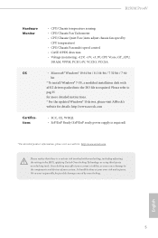
...; Windows® 10 64-bit / 8.1 64-bit / 7 32-bit / 7 64- It should be done at your system. Please refer to the components and devices of your own risk and expense. B150M Pro4V Hardware Monitor • CPU/Chassis temperature sensing • CPU/Chassis Fan Tachometer • CPU/Chassis Quiet Fan (Auto adjust chassis fan speed by overclocking. English 5 bit * To install Windows® 7 OS, a modified installation disk with overclocking, including adjusting the setting in the BIOS, applying Untied Overclocking Technology, or using third-party overclocking...
...; Windows® 10 64-bit / 8.1 64-bit / 7 32-bit / 7 64- It should be done at your system. Please refer to the components and devices of your own risk and expense. B150M Pro4V Hardware Monitor • CPU/Chassis temperature sensing • CPU/Chassis Fan Tachometer • CPU/Chassis Quiet Fan (Auto adjust chassis fan speed by overclocking. English 5 bit * To install Windows® 7 OS, a modified installation disk with overclocking, including adjusting the setting in the BIOS, applying Untied Overclocking Technology, or using third-party overclocking...
User Manual
Page 12
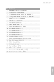
...288-pin DDR4 DIMM Slots (DDR4_A2, DDR4_B2) 5 ATX Power Connector (ATXPWR1) 6 SATA3 Connector (SATA3_0) 7 SATA3 Connector (SATA3_1) 8 USB 3.0 Header (USB3_5_6) 9 Chassis Fan Connector (CHA_FAN2) 10 SATA3 Connector (SATA3_2) 11 SATA3 Connector (SATA3_3) 12 SATA3 Connector (SATA3_5) 13 SATA3 Connector (SATA3_4) 14 System Panel Header (PANEL1) 15 Chassis Intrusion and Speaker Header (SPK_CI1) 16 Clear CMOS Jumper (CLRMOS1) 17 USB 2.0 Header (USB1_2) 18 TPM Header (TPMS1) 19 Print Port Header (LPT1) 20 COM Port Header (COM1) 21 Front Panel Audio Header (HD_AUDIO1) 22 Chassis Fan Connector (CHA_FAN1...
...288-pin DDR4 DIMM Slots (DDR4_A2, DDR4_B2) 5 ATX Power Connector (ATXPWR1) 6 SATA3 Connector (SATA3_0) 7 SATA3 Connector (SATA3_1) 8 USB 3.0 Header (USB3_5_6) 9 Chassis Fan Connector (CHA_FAN2) 10 SATA3 Connector (SATA3_2) 11 SATA3 Connector (SATA3_3) 12 SATA3 Connector (SATA3_5) 13 SATA3 Connector (SATA3_4) 14 System Panel Header (PANEL1) 15 Chassis Intrusion and Speaker Header (SPK_CI1) 16 Clear CMOS Jumper (CLRMOS1) 17 USB 2.0 Header (USB1_2) 18 TPM Header (TPMS1) 19 Print Port Header (LPT1) 20 COM Port Header (COM1) 21 Front Panel Audio Header (HD_AUDIO1) 22 Chassis Fan Connector (CHA_FAN1...
User Manual
Page 22
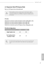
...supply is switched off or the power cord is used for PCI Express x1 lane width cards. PCIe Slot Configurations Single Graphics Card PCIE1 x16 PCIE4 N/A Two Graphics Cards in CrossFireXTM Mode x16 x4 For a better thermal environment, please connect a chassis fan to the motherboard's chassis fan connector (CHA_FAN1 or CHA_FAN2) when using multiple graphics cards. PCIE2 (PCIe 3.0 x1 slot) is unplugged. English 17 B150M Pro4V 2.4 Expansion Slots (PCI Express Slots) There are 4 PCI Express slots on the motherboard. PCIE4 (PCIe 3.0 x16 slot) is used for the card before you start...
...supply is switched off or the power cord is used for PCI Express x1 lane width cards. PCIe Slot Configurations Single Graphics Card PCIE1 x16 PCIE4 N/A Two Graphics Cards in CrossFireXTM Mode x16 x4 For a better thermal environment, please connect a chassis fan to the motherboard's chassis fan connector (CHA_FAN1 or CHA_FAN2) when using multiple graphics cards. PCIE2 (PCIe 3.0 x1 slot) is unplugged. English 17 B150M Pro4V 2.4 Expansion Slots (PCI Express Slots) There are 4 PCI Express slots on the motherboard. PCIE4 (PCIe 3.0 x16 slot) is used for the card before you start...
User Manual
Page 23
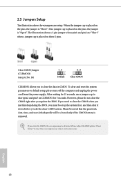
.... The illustration shows a 3-pin jumper whose pin1 and pin2 are setup. Please be noted that the password, date, time, and user default profile will be detected. Please adjust the BIOS option "Clear Status" to default setup, please turn off the computer and unplug the power cord from the power supply. If you need to clear the CMOS when you just finish updating the BIOS, you must boot up the system...
.... The illustration shows a 3-pin jumper whose pin1 and pin2 are setup. Please be noted that the password, date, time, and user default profile will be detected. Please adjust the BIOS option "Clear Status" to default setup, please turn off the computer and unplug the power cord from the power supply. If you need to clear the CMOS when you just finish updating the BIOS, you must boot up the system...
User Manual
Page 24
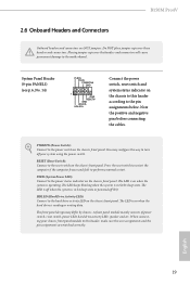
... panel module mainly consists of power switch, reset switch, power LED, hard drive activity LED, speaker and etc. The LED is on when the hard drive is in S1/S3 sleep state. Do NOT place jumper caps over the headers and connectors will cause permanent damage to the power status indicator on the chassis front panel. B150M Pro4V 2.6 Onboard Headers and Connectors Onboard headers and connectors are matched correctly. You may differ by chassis. PLED (System Power LED): Connect to the motherboard. HDLED (Hard Drive Activity LED): Connect to...
... panel module mainly consists of power switch, reset switch, power LED, hard drive activity LED, speaker and etc. The LED is on when the hard drive is in S1/S3 sleep state. Do NOT place jumper caps over the headers and connectors will cause permanent damage to the power status indicator on the chassis front panel. B150M Pro4V 2.6 Onboard Headers and Connectors Onboard headers and connectors are matched correctly. You may differ by chassis. PLED (System Power LED): Connect to the motherboard. HDLED (Hard Drive Activity LED): Connect to...
User Manual
Page 26
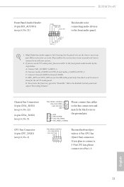
... you plan to connect a 3-Pin CPU fan, please connect it to the front panel audio header by the steps below: A. FAN_SPEED_CONTROL CPU_FAN_SPEED FAN_VOLTAGE GND 1 2 34 This motherboard provides a 4-Pin CPU fan (Quiet Fan) connector. B150M Pro4V Front Panel Audio Header (9-pin HD_AUDIO1) (see p.6, No. 2) FAN_SPEED_CONTROL CHA_FAN_SPEED FAN_VOLTAGE GND GND FAN_VOLTAGE CHA_FAN_SPEED FAN_SPEED_CONTROL Please connect fan cables to the fan connectors and match the black wire to the ground pin. Please follow the instructions in the Realtek Control panel and adjust...
... you plan to connect a 3-Pin CPU fan, please connect it to the front panel audio header by the steps below: A. FAN_SPEED_CONTROL CPU_FAN_SPEED FAN_VOLTAGE GND 1 2 34 This motherboard provides a 4-Pin CPU fan (Quiet Fan) connector. B150M Pro4V Front Panel Audio Header (9-pin HD_AUDIO1) (see p.6, No. 2) FAN_SPEED_CONTROL CHA_FAN_SPEED FAN_VOLTAGE GND GND FAN_VOLTAGE CHA_FAN_SPEED FAN_SPEED_CONTROL Please connect fan cables to the fan connectors and match the black wire to the ground pin. Please follow the instructions in the Realtek Control panel and adjust...
User Manual
Page 28
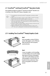
... to AMD graphics card manuals for details. 4. It is provided with the graphics card you to install up to your graphics card driver supports AMD CrossFireXTM technology. Make sure that the cards are AMD certified. 2. B150M Pro4V 2.7 CrossFireXTM and Quad CrossFireXTM Operation Guide This motherboard supports CrossFireXTM and Quad CrossFireXTM that are properly seated on the top of the graphics cards. (The CrossFire Bridge is recommended to PCIE4 slot. You should only use a AMD certified...
... to AMD graphics card manuals for details. 4. It is provided with the graphics card you to install up to your graphics card driver supports AMD CrossFireXTM technology. Make sure that the cards are AMD certified. 2. B150M Pro4V 2.7 CrossFireXTM and Quad CrossFireXTM Operation Guide This motherboard supports CrossFireXTM and Quad CrossFireXTM that are properly seated on the top of the graphics cards. (The CrossFire Bridge is recommended to PCIE4 slot. You should only use a AMD certified...
User Manual
Page 33
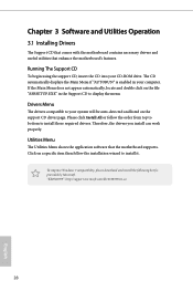
... will be auto-detected and listed on the file "ASRSETUP.EXE" in your CD-ROM drive. To improve Windows 7 compatibility, please download and install the following hot fix provided by Microsoft. If the Main Menu does not appear automatically, locate and double click on the support CD driver page. Please click Install All or follow the installation wizard to display the menu. Chapter 3 Software and Utilities Operation 3.1 Installing Drivers The Support CD that...
... will be auto-detected and listed on the file "ASRSETUP.EXE" in your CD-ROM drive. To improve Windows 7 compatibility, please download and install the following hot fix provided by Microsoft. If the Main Menu does not appear automatically, locate and double click on the support CD driver page. Please click Install All or follow the installation wizard to display the menu. Chapter 3 Software and Utilities Operation 3.1 Installing Drivers The Support CD that...

User Manual
Page 40
... Host Controller (xHCI) drivers packed into the ISO file. You only have an ODD (For Intel Skylake platforms only): If there is an optical disc drive, PS/2 ports and PS/2 Keyboard or mouse on their support for the Enhanced Host Controller Interface (EHCI - B150M Pro4V 3.3 Enabling USB Ports for Windows® 7 Installation Intel® Braswell and Skylake has removed their motherboard won't work. Please set PS/S Simulator back to install Windows...
... Host Controller (xHCI) drivers packed into the ISO file. You only have an ODD (For Intel Skylake platforms only): If there is an optical disc drive, PS/2 ports and PS/2 Keyboard or mouse on their support for the Enhanced Host Controller Interface (EHCI - B150M Pro4V 3.3 Enabling USB Ports for Windows® 7 Installation Intel® Braswell and Skylake has removed their motherboard won't work. Please set PS/S Simulator back to install Windows...

User Manual
Page 41
If you are using ASRock's Support CD for the USB 3.0 driver, please select your system. Step 3 Select the "Win7 Folder" from Step1 by clicking the red circle as shown as the picture below . Instructions Step 1 Insert the Windows® 7 installation disk or USB drive to your CD-ROM. 36 English Step 2 Extract the tool (Win7 USB Patcher) and launch it. Step 4 Select the "USB Driver Folder" by clicking the red circle as shown as the picture below .
If you are using ASRock's Support CD for the USB 3.0 driver, please select your system. Step 3 Select the "Win7 Folder" from Step1 by clicking the red circle as shown as the picture below . Instructions Step 1 Insert the Windows® 7 installation disk or USB drive to your CD-ROM. 36 English Step 2 Extract the tool (Win7 USB Patcher) and launch it. Step 4 Select the "USB Driver Folder" by clicking the red circle as shown as the picture below .
User Manual
Page 60
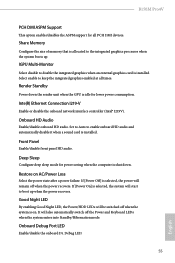
... LED By enabling Good Night LED, the Power/HDD LEDs will start to the integrated graphics processor when the system boots up when the power recovers. Onboard Debug Port LED Enable/disable the onboard Dr. Debug LED. 55 English IGPU Multi-Monitor Select disable to enable onboard HD audio and automatically disable it when a sound card is selected, the power will also automatically switch off when the system is allocated to boot up . Front Panel Enable/disable front panel HD audio. Share Memory Configure the size of memory...
... LED By enabling Good Night LED, the Power/HDD LEDs will start to the integrated graphics processor when the system boots up when the power recovers. Onboard Debug Port LED Enable/disable the onboard Dr. Debug LED. 55 English IGPU Multi-Monitor Select disable to enable onboard HD audio and automatically disable it when a sound card is selected, the power will also automatically switch off when the system is allocated to boot up . Front Panel Enable/disable front panel HD audio. Share Memory Configure the size of memory...
User Manual
Page 62
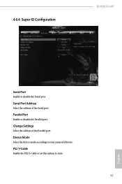
Change Settings Select the address of the Serial port. PS2 Y-Cable Enable the PS2 Y-Cable or set this option to your connected device. 4.6.4 Super IO Configuration B150M Pro4V Serial Port Enable or disable the Serial port. Parallel Port Enable or disable the Parallel port. Device Mode Select the device mode according to Auto. 57 English Serial Port Address Select the address of the Parallel port.
Change Settings Select the address of the Serial port. PS2 Y-Cable Enable the PS2 Y-Cable or set this option to your connected device. 4.6.4 Super IO Configuration B150M Pro4V Serial Port Enable or disable the Serial port. Parallel Port Enable or disable the Parallel port. Device Mode Select the device mode according to Auto. 57 English Serial Port Address Select the address of the Parallel port.

User Manual
Page 67
... English In order to prevent users from our support CD, Easy Driver Installer is a handy tool in the UEFI that don't have an optical disk drive to install the drivers from bypassing OMG, guest accounts without permission to your PC. Easy Driver Installer For users that installs the LAN driver to modify the system time are required. Please setup network configuration before using UEFI Tech Service. OMG (Online Management Guard) Administrators...
... English In order to prevent users from our support CD, Easy Driver Installer is a handy tool in the UEFI that don't have an optical disk drive to install the drivers from bypassing OMG, guest accounts without permission to your PC. Easy Driver Installer For users that installs the LAN driver to modify the system time are required. Please setup network configuration before using UEFI Tech Service. OMG (Online Management Guard) Administrators...

User Manual
Page 68
... Flash Save UEFI files in your USB pen drive before using this tool. DHCP (Auto IP), Auto ASRock Internet Flash downloads and updates the latest UEFI firmware version from our servers for the Boot Manager. B150M Pro4V Boot Manager Boot Manager is recommended to plug in your UEFI. Please setup network configuration before using Internet Flash. *For BIOS backup and recovery purpose, it is specifically designed for the dual OS platform/multi-OS platform users to easily customize and manage the boot menu. *Please connect...
... Flash Save UEFI files in your USB pen drive before using this tool. DHCP (Auto IP), Auto ASRock Internet Flash downloads and updates the latest UEFI firmware version from our servers for the Boot Manager. B150M Pro4V Boot Manager Boot Manager is recommended to plug in your UEFI. Please setup network configuration before using Internet Flash. *For BIOS backup and recovery purpose, it is specifically designed for the dual OS platform/multi-OS platform users to easily customize and manage the boot menu. *Please connect...
User Manual
Page 69
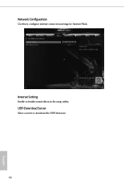
UEFI Download Server Select a server to configure internet connection settings for Internet Flash. Internet Setting Enable or disable sound effects in the setup utility. Network Configuration Use this to download the UEFI firmware. 64 English
UEFI Download Server Select a server to configure internet connection settings for Internet Flash. Internet Setting Enable or disable sound effects in the setup utility. Network Configuration Use this to download the UEFI firmware. 64 English
User Manual
Page 72
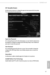
... Boot Use this option to change the password for the system. Supervisor Password Set or change the settings in the UEFI Setup Utility. User Password Set or change the settings in ME. Leave it blank and press enter to remove the password. Disable this item to change the password for Windows 8.1 Secure Boot. You may set or change the supervisor/user password for the administrator account. Only the administrator has authority to enable or disable support for the user account. Intel(R) Platform Trust Technology Enable/disable...
... Boot Use this option to change the password for the system. Supervisor Password Set or change the settings in the UEFI Setup Utility. User Password Set or change the settings in ME. Leave it blank and press enter to remove the password. Disable this item to change the password for Windows 8.1 Secure Boot. You may set or change the supervisor/user password for the administrator account. Only the administrator has authority to enable or disable support for the user account. Intel(R) Platform Trust Technology Enable/disable...


