
User Manual
Page 4
...I/O Panel 8 Chapter 2 Installation 10 2.1 Installing the CPU 11 2.2 Installing the CPU Fan and Heatsink 14 2.3 Installing Memory Modules (DIMM) 15 2.4 Expansion Slots (PCI Express Slots) 17 2.5 Jumpers Setup 18 2.6 Onboard Headers and Connectors 19 2.7 CrossFireXTM and Quad CrossFireXTM Operation Guide 23 2.7.1 Installing Two CrossFireXTM-Ready Graphics Cards 23 2.7.2 Driver Installation and Setup 25 Chapter 3 Software and Utilities Operation 26 3.1 Installing Drivers 26 3.2 ASRock Live Update & APP Shop 27 3.2.1 UI Overview 27 3.2.2 Apps 28 3.2.3 BIOS & Drivers...
...I/O Panel 8 Chapter 2 Installation 10 2.1 Installing the CPU 11 2.2 Installing the CPU Fan and Heatsink 14 2.3 Installing Memory Modules (DIMM) 15 2.4 Expansion Slots (PCI Express Slots) 17 2.5 Jumpers Setup 18 2.6 Onboard Headers and Connectors 19 2.7 CrossFireXTM and Quad CrossFireXTM Operation Guide 23 2.7.1 Installing Two CrossFireXTM-Ready Graphics Cards 23 2.7.2 Driver Installation and Setup 25 Chapter 3 Software and Utilities Operation 26 3.1 Installing Drivers 26 3.2 ASRock Live Update & APP Shop 27 3.2.1 UI Overview 27 3.2.2 Apps 28 3.2.3 BIOS & Drivers...
User Manual
Page 6
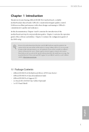
... the latest VGA cards and CPU support list on ASRock's website without notice. B150M Pro4 Chapter 1 Introduction hank you for speciic information about the model you require technical support related to this documentation will be subject to quality and endurance. ASRock website http://www.asrock.com. 1.1 Package Contents • ASRock B150M Pro4 Motherboard (Micro ATX Form Factor) • ASRock B150M Pro4 Quick Installation Guide • ASRock B150M Pro4 Support CD • 2 x Serial ATA (SATA) Data Cables (Optional) • 1 x I/O Panel Shield 1 English...
... the latest VGA cards and CPU support list on ASRock's website without notice. B150M Pro4 Chapter 1 Introduction hank you for speciic information about the model you require technical support related to this documentation will be subject to quality and endurance. ASRock website http://www.asrock.com. 1.1 Package Contents • ASRock B150M Pro4 Motherboard (Micro ATX Form Factor) • ASRock B150M Pro4 Quick Installation Guide • ASRock B150M Pro4 Support CD • 2 x Serial ATA (SATA) Data Cables (Optional) • 1 x I/O Panel Shield 1 English...

User Manual
Page 8
...; Supports Energy Eicient Ethernet 802.3az • Supports PXE Rear Panel I/O • 1 x PS/2 Mouse/Keyboard Port • 1 x D-Sub Port • 1 x DVI-D Port • 1 x HDMI Port • 4 x USB 3.0 Ports (Supports ESD Protection (ASRock Full Spike Protection)) • 1 x RJ-45 LAN Port with LED (ACT/LINK LED and SPEED LED) • HD Audio Jacks: Side Speaker / Rear Speaker / Central / Bass / Line in / Front Speaker / Microphone Storage • 6 x SATA3 6.0 Gb/s Connectors, support NCQ, AHCI and Hot Plug 3 English B150M Pro4 • Supports DVI-D with max.
...; Supports Energy Eicient Ethernet 802.3az • Supports PXE Rear Panel I/O • 1 x PS/2 Mouse/Keyboard Port • 1 x D-Sub Port • 1 x DVI-D Port • 1 x HDMI Port • 4 x USB 3.0 Ports (Supports ESD Protection (ASRock Full Spike Protection)) • 1 x RJ-45 LAN Port with LED (ACT/LINK LED and SPEED LED) • HD Audio Jacks: Side Speaker / Rear Speaker / Central / Bass / Line in / Front Speaker / Microphone Storage • 6 x SATA3 6.0 Gb/s Connectors, support NCQ, AHCI and Hot Plug 3 English B150M Pro4 • Supports DVI-D with max.

User Manual
Page 9
... pin ATX Power Connector • 1 x 8 pin 12V Power Connector • 1 x Front Panel Audio Connector • 1 x USB 2.0 Header (Supports 2 USB 2.0 ports) (Supports ESD Protection (ASRock Full Spike Protection)) • 1 x USB 3.0 Header (Supports 2 USB 3.0 ports) (Supports ESD Protection (ASRock Full Spike Protection)) BIOS Feature • 128Mb AMI UEFI Legal BIOS with xHCI drivers packed into the ISO ile is required. port • ACPI 1.1 Compliant wake up events • SMBIOS 2.3.1 Support • DRAM Voltage Multi-adjustment Hardware Monitor • CPU/Chassis temperature...
... pin ATX Power Connector • 1 x 8 pin 12V Power Connector • 1 x Front Panel Audio Connector • 1 x USB 2.0 Header (Supports 2 USB 2.0 ports) (Supports ESD Protection (ASRock Full Spike Protection)) • 1 x USB 3.0 Header (Supports 2 USB 3.0 ports) (Supports ESD Protection (ASRock Full Spike Protection)) BIOS Feature • 128Mb AMI UEFI Legal BIOS with xHCI drivers packed into the ISO ile is required. port • ACPI 1.1 Compliant wake up events • SMBIOS 2.3.1 Support • DRAM Voltage Multi-adjustment Hardware Monitor • CPU/Chassis temperature...

User Manual
Page 12
...288-pin DDR4 DIMM Slots (DDR4_A2, DDR4_B2) 5 ATX Power Connector (ATXPWR1) 6 SATA3 Connector (SATA3_0) 7 SATA3 Connector (SATA3_1) 8 USB 3.0 Header (USB3_5_6) 9 Chassis Fan Connector (CHA_FAN2) 10 SATA3 Connector (SATA3_2) 11 SATA3 Connector (SATA3_3) 12 SATA3 Connector (SATA3_5) 13 SATA3 Connector (SATA3_4) 14 System Panel Header (PANEL1) 15 Chassis Intrusion and Speaker Header (SPK_CI1) 16 Clear CMOS Jumper (CLRMOS1) 17 USB 2.0 Header (USB1_2) 18 TPM Header (TPMS1) 19 Print Port Header (LPT1) 20 COM Port Header (COM1) 21 Front Panel Audio Header (HD_AUDIO1) 22 Chassis Fan Connector (CHA_FAN1...
...288-pin DDR4 DIMM Slots (DDR4_A2, DDR4_B2) 5 ATX Power Connector (ATXPWR1) 6 SATA3 Connector (SATA3_0) 7 SATA3 Connector (SATA3_1) 8 USB 3.0 Header (USB3_5_6) 9 Chassis Fan Connector (CHA_FAN2) 10 SATA3 Connector (SATA3_2) 11 SATA3 Connector (SATA3_3) 12 SATA3 Connector (SATA3_5) 13 SATA3 Connector (SATA3_4) 14 System Panel Header (PANEL1) 15 Chassis Intrusion and Speaker Header (SPK_CI1) 16 Clear CMOS Jumper (CLRMOS1) 17 USB 2.0 Header (USB1_2) 18 TPM Header (TPMS1) 19 Print Port Header (LPT1) 20 COM Port Header (COM1) 21 Front Panel Audio Header (HD_AUDIO1) 22 Chassis Fan Connector (CHA_FAN1...

User Manual
Page 22
... settings for the card before you start the installation. B150M Pro4 2.4 Expansion Slots (PCI Express Slots) here are 4 PCI Express slots on the motherboard. English 17 PCIE3 (PCIe 3.0 x1 slot) is unplugged. PCIE2 (PCIe 3.0 x1 slot) is used for PCI Express x16 lane width graphics cards. PCIe Slot Conigurations Single Graphics Card PCIE1 x16 PCIE4 N/A Two Graphics Cards in CrossFireXTM Mode x16 x4 For a better thermal environment, please connect a chassis fan to the motherboard's chassis fan connector (CHA_FAN1 or CHA_FAN2) when using multiple graphics cards. PCIe...
... settings for the card before you start the installation. B150M Pro4 2.4 Expansion Slots (PCI Express Slots) here are 4 PCI Express slots on the motherboard. English 17 PCIE3 (PCIe 3.0 x1 slot) is unplugged. PCIE2 (PCIe 3.0 x1 slot) is used for PCI Express x16 lane width graphics cards. PCIe Slot Conigurations Single Graphics Card PCIE1 x16 PCIE4 N/A Two Graphics Cards in CrossFireXTM Mode x16 x4 For a better thermal environment, please connect a chassis fan to the motherboard's chassis fan connector (CHA_FAN1 or CHA_FAN2) when using multiple graphics cards. PCIe...

User Manual
Page 23
... the password, date, time, and user default proile will be detected. If you need to clear the CMOS when you just inish updating the BIOS, you must boot up the system irst, and then shut it down before you to short pin2 and pin3 on the pins, the jumper is "Open". Please adjust the BIOS option "Clear Status" to default setup, please turn of previous chassis intrusion status. 2.5 Jumpers Setup...
... the password, date, time, and user default proile will be detected. If you need to clear the CMOS when you just inish updating the BIOS, you must boot up the system irst, and then shut it down before you to short pin2 and pin3 on the pins, the jumper is "Open". Please adjust the BIOS option "Clear Status" to default setup, please turn of previous chassis intrusion status. 2.5 Jumpers Setup...

User Manual
Page 24
... to turn of power switch, reset switch, power LED, hard drive activity LED, speaker and etc. Note the positive and negative pins before connecting the cables. PLED (System Power LED): Connect to the motherboard. English 19 System Panel Header (9-pin PANEL1) (see p.6, No. 14) PLED+ PLEDPWRBTN# GND 1 GND RESET# GND HDLEDHDLED+ Connect the power switch, reset switch and system status indicator on when the hard drive is in S1/S3 sleep state. Do NOT place jumper caps over the headers and connectors will...
... to turn of power switch, reset switch, power LED, hard drive activity LED, speaker and etc. Note the positive and negative pins before connecting the cables. PLED (System Power LED): Connect to the motherboard. English 19 System Panel Header (9-pin PANEL1) (see p.6, No. 14) PLED+ PLEDPWRBTN# GND 1 GND RESET# GND HDLEDHDLED+ Connect the power switch, reset switch and system status indicator on when the hard drive is in S1/S3 sleep state. Do NOT place jumper caps over the headers and connectors will...
User Manual
Page 26
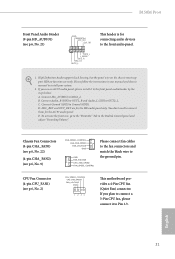
... you use an AC'97 audio panel, please install it to Pin 1-3. B150M Pro4 Front Panel Audio Header (9-pin HD_AUDIO1) (see p.6, No. 21) GND PRESENCE# MIC_RET OUT_RET 1 OUT2_L J_SENSE OUT2_R MIC2_R MIC2_L his motherboard provides a 4-Pin CPU fan (Quiet Fan) connector. Chassis Fan Connectors (4-pin CHA_FAN1) (see p.6, No. 22) (4-pin CHA_FAN2) (see p.6, No. 9) FAN_SPEED_CONTROL CHA_FAN_SPEED FAN_VOLTAGE GND GND FAN_VOLTAGE CHA_FAN_SPEED FAN_SPEED_CONTROL Please connect fan cables to the fan connectors and match the black wire to Ground (GND). D. High Deinition Audio supports...
... you use an AC'97 audio panel, please install it to Pin 1-3. B150M Pro4 Front Panel Audio Header (9-pin HD_AUDIO1) (see p.6, No. 21) GND PRESENCE# MIC_RET OUT_RET 1 OUT2_L J_SENSE OUT2_R MIC2_R MIC2_L his motherboard provides a 4-Pin CPU fan (Quiet Fan) connector. Chassis Fan Connectors (4-pin CHA_FAN1) (see p.6, No. 22) (4-pin CHA_FAN2) (see p.6, No. 9) FAN_SPEED_CONTROL CHA_FAN_SPEED FAN_VOLTAGE GND GND FAN_VOLTAGE CHA_FAN_SPEED FAN_SPEED_CONTROL Please connect fan cables to the fan connectors and match the black wire to Ground (GND). D. High Deinition Audio supports...
User Manual
Page 28
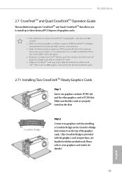
... identical PCI Express x16 graphics cards. 1. Download the drivers from the AMD's website: www.amd.com 3. Diferent CrossFireXTM cards may require diferent methods to use identical CrossFireXTM-ready graphics cards that allows you to install up to your graphics card driver supports AMD CrossFireXTM technology. Make sure that your graphics card vendor for details.) English 23 Please refer to the AMD's website for detailed installation guide. 2.7.1 Installing Two CrossFireXTM-Ready Graphics Cards Step 1 Insert one graphics card into PCIE1 slot...
... identical PCI Express x16 graphics cards. 1. Download the drivers from the AMD's website: www.amd.com 3. Diferent CrossFireXTM cards may require diferent methods to use identical CrossFireXTM-ready graphics cards that allows you to install up to your graphics card driver supports AMD CrossFireXTM technology. Make sure that your graphics card vendor for details.) English 23 Please refer to the AMD's website for detailed installation guide. 2.7.1 Installing Two CrossFireXTM-Ready Graphics Cards Step 1 Insert one graphics card into PCIE1 slot...

User Manual
Page 31
... to install it. Drivers Menu he drivers compatible to display the menu. "KB2720599": http://support.microsot.com/kb/2720599/en-us 26 English Click on the support CD driver page. he Utilities Menu shows the application sotware that enhance the motherboard's features. herefore, the drivers you install can work properly. Utilities Menu he CD automatically displays the Main Menu if "AUTORUN" is enabled in the Support CD to your CD-ROM drive. Please click Install All...
... to install it. Drivers Menu he drivers compatible to display the menu. "KB2720599": http://support.microsot.com/kb/2720599/en-us 26 English Click on the support CD driver page. he Utilities Menu shows the application sotware that enhance the motherboard's features. herefore, the drivers you install can work properly. Utilities Menu he CD automatically displays the Main Menu if "AUTORUN" is enabled in the Support CD to your CD-ROM drive. Please click Install All...

User Manual
Page 38
B150M Pro4 3.3 Enabling USB Ports for Windows® 7 Installation Intel® Braswell and Skylake has removed their motherboard won't work. You've got nothing: If you do not have an optical disc drive, please ind another computer and follow the instructions below and go ahead to create a new ISO ile with the Intel® USB 3.0 eXtensible Host Controller (xHCI) drivers packed into the ISO ile. USB2...
B150M Pro4 3.3 Enabling USB Ports for Windows® 7 Installation Intel® Braswell and Skylake has removed their motherboard won't work. You've got nothing: If you do not have an optical disc drive, please ind another computer and follow the instructions below and go ahead to create a new ISO ile with the Intel® USB 3.0 eXtensible Host Controller (xHCI) drivers packed into the ISO ile. USB2...

User Manual
Page 39
Step 2 Extract the tool (Win7 USB Patcher) and launch it. If you are using ASRock's Support CD for the USB 3.0 driver, please select your system. Step 3 Select the "Win7 Folder" from Step1 by clicking the red circle as shown as the picture below . Step 4 Select the "USB Driver Folder" by clicking the red circle as shown as the picture below . Instructions Step 1 Insert the Windows® 7 installation disk or USB drive to your CD-ROM. 34 English
Step 2 Extract the tool (Win7 USB Patcher) and launch it. If you are using ASRock's Support CD for the USB 3.0 driver, please select your system. Step 3 Select the "Win7 Folder" from Step1 by clicking the red circle as shown as the picture below . Step 4 Select the "USB Driver Folder" by clicking the red circle as shown as the picture below . Instructions Step 1 Insert the Windows® 7 installation disk or USB drive to your CD-ROM. 34 English

User Manual
Page 41
... reset button on . You may not exactly match what you wish to conigure your screen. 4.1.1 UEFI Menu Bar he top of and then back on the system chassis. Because the UEFI sotware is constantly being updated, the following selections: Main For setting system time/date information OC Tweaker For overclocking conigurations Advanced For advanced system conigurations Tool Useful tools H/W Monitor Displays current hardware status Boot...
... reset button on . You may not exactly match what you wish to conigure your screen. 4.1.1 UEFI Menu Bar he top of and then back on the system chassis. Because the UEFI sotware is constantly being updated, the following selections: Main For setting system time/date information OC Tweaker For overclocking conigurations Advanced For advanced system conigurations Tool Useful tools H/W Monitor Displays current hardware status Boot...

User Manual
Page 56
... installed. Front Panel Enable/disable front panel HD audio. If [Power On] is on AC/Power Loss Select the power state ater a power failure. It will be switched of when the system is selected, the system will remain of the Power and Keyboard LEDs when the system enters into Standby/Hibernation mode. B150M Pro4 PCH DMI ASPM Support his option enables/disables the ASPM support for all times. Onboard HD Audio Enable/disable onboard HD audio. Set to Auto to boot up . Deep Sleep...
... installed. Front Panel Enable/disable front panel HD audio. If [Power On] is on AC/Power Loss Select the power state ater a power failure. It will be switched of when the system is selected, the system will remain of the Power and Keyboard LEDs when the system enters into Standby/Hibernation mode. B150M Pro4 PCH DMI ASPM Support his option enables/disables the ASPM support for all times. Onboard HD Audio Enable/disable onboard HD audio. Set to Auto to boot up . Deep Sleep...

User Manual
Page 58
Device Mode Select the device mode according to Auto. 53 English PS2 Y-Cable Enable the PS2 Y-Cable or set this option to your connected device. 4.4.4 Super IO Coniguration B150M Pro4 Serial Port Enable or disable the Serial port. Serial Port Address Select the address of the Parallel port. Change Settings Select the address of the Serial port. Parallel Port Enable or disable the Parallel port.
Device Mode Select the device mode according to Auto. 53 English PS2 Y-Cable Enable the PS2 Y-Cable or set this option to your connected device. 4.4.4 Super IO Coniguration B150M Pro4 Serial Port Enable or disable the Serial port. Serial Port Address Select the address of the Parallel port. Change Settings Select the address of the Serial port. Parallel Port Enable or disable the Parallel port.

User Manual
Page 61
his should be enabled for the complete USB keyboard legacy support for USB 2.0 devices. 4.4.6 USB Coniguration Legacy USB Support Enable or disable Legacy OS Support for non-USB aware OS. *Enable this option if you encounter USB compatibility issues it is recommended to support USB devices under the UEFI setup and Windows/Linux operating systems only. Port 60/64 Emulation Enable the support of I/O port 60h/64h emulation. Select UEFI Setup Only to disable legacy USB support. If you install Windows 7. 56 English
his should be enabled for the complete USB keyboard legacy support for USB 2.0 devices. 4.4.6 USB Coniguration Legacy USB Support Enable or disable Legacy OS Support for non-USB aware OS. *Enable this option if you encounter USB compatibility issues it is recommended to support USB devices under the UEFI setup and Windows/Linux operating systems only. Port 60/64 Emulation Enable the support of I/O port 60h/64h emulation. Select UEFI Setup Only to disable legacy USB support. If you install Windows 7. 56 English
User Manual
Page 63
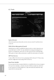
... required drivers automatically. 58 English Please setup network coniguration before using UEFI Tech Service. Easy Driver Installer For users that installs the LAN driver to establish an internet curfew or restrict internet access at speciied times via an USB storage device, then downloads and installs the other users. In order to prevent users from our support CD, Easy Driver Installer is a handy tool in the UEFI that don't have an optical disk drive to install the drivers from...
... required drivers automatically. 58 English Please setup network coniguration before using UEFI Tech Service. Easy Driver Installer For users that installs the LAN driver to establish an internet curfew or restrict internet access at speciied times via an USB storage device, then downloads and installs the other users. In order to prevent users from our support CD, Easy Driver Installer is a handy tool in the UEFI that don't have an optical disk drive to install the drivers from...

User Manual
Page 65
...), Auto ASRock Internet Flash downloads and updates the latest UEFI irmware version from our servers for Internet Flash. 60 English Dehumidiier CPU Fan Setting Conigure the speed of the ROM images are outdated or corrupted, switch to the other lash ROM and execute Secure Backup UEFI to duplicate the current working ROM image to conigure internet connection settings for you. Please setup network coniguration before using Internet Flash. *For BIOS backup and recovery purpose, it is enabled. Max...
...), Auto ASRock Internet Flash downloads and updates the latest UEFI irmware version from our servers for Internet Flash. 60 English Dehumidiier CPU Fan Setting Conigure the speed of the ROM images are outdated or corrupted, switch to the other lash ROM and execute Secure Backup UEFI to duplicate the current working ROM image to conigure internet connection settings for you. Please setup network coniguration before using Internet Flash. *For BIOS backup and recovery purpose, it is enabled. Max...

User Manual
Page 69
... the UEFI Setup Utility. Users are unable to change the settings in ME. Leave it blank and press enter to enable or disable support for the administrator account. Intel(R) Platform Trust Technology Enable/disable Intel PTT in the UEFI Setup Utility. Supervisor Password Set or change the password for the system. Disable this item to remove the password. Leave it blank and press enter to use discrete TPM Module. 64 English Secure Boot Use this option to remove the password.
... the UEFI Setup Utility. Users are unable to change the settings in ME. Leave it blank and press enter to enable or disable support for the administrator account. Intel(R) Platform Trust Technology Enable/disable Intel PTT in the UEFI Setup Utility. Supervisor Password Set or change the password for the system. Disable this item to remove the password. Leave it blank and press enter to use discrete TPM Module. 64 English Secure Boot Use this option to remove the password.


