
User Manual
Page 4
... Contents 1 1.2 Specifications 2 1.3 Motherboard Layout 6 1.4 I/O Panel 8 Chapter 2 Installation 10 2.1 Installing the CPU 11 2.2 Installing the CPU Fan and Heatsink 14 2.3 Installing Memory Modules (DIMM) 15 2.4 Expansion Slots (PCI Express Slots) 17 2.5 Jumpers Setup 18 2.6 Onboard Headers and Connectors 19 2.7 CrossFireXTM and Quad CrossFireXTM Operation Guide 23 2.7.1 Installing Two CrossFireXTM-Ready Graphics Cards 23 2.7.2 Driver Installation and Setup 25 Chapter 3 Software and Utilities Operation 26 3.1 Installing Drivers 26 3.2 ASRock Live Update & APP...
... Contents 1 1.2 Specifications 2 1.3 Motherboard Layout 6 1.4 I/O Panel 8 Chapter 2 Installation 10 2.1 Installing the CPU 11 2.2 Installing the CPU Fan and Heatsink 14 2.3 Installing Memory Modules (DIMM) 15 2.4 Expansion Slots (PCI Express Slots) 17 2.5 Jumpers Setup 18 2.6 Onboard Headers and Connectors 19 2.7 CrossFireXTM and Quad CrossFireXTM Operation Guide 23 2.7.1 Installing Two CrossFireXTM-Ready Graphics Cards 23 2.7.2 Driver Installation and Setup 25 Chapter 3 Software and Utilities Operation 26 3.1 Installing Drivers 26 3.2 ASRock Live Update & APP...
User Manual
Page 6
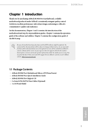
... control. Chapter 4 contains the configuration guide of the software and utilities. You may find the latest VGA cards and CPU support list on ASRock's website without notice. ASRock website http://www.asrock.com. 1.1 Package Contents • ASRock B150M Pro4 Motherboard (Micro ATX Form Factor) • ASRock B150M Pro4 Quick Installation Guide • ASRock B150M Pro4 Support CD • 2 x Serial ATA (SATA) Data Cables (Optional) • 1 x I/O Panel Shield 1 English Chapter 3 contains the operation guide of the BIOS setup. In this documentation occur, the updated version...
... control. Chapter 4 contains the configuration guide of the software and utilities. You may find the latest VGA cards and CPU support list on ASRock's website without notice. ASRock website http://www.asrock.com. 1.1 Package Contents • ASRock B150M Pro4 Motherboard (Micro ATX Form Factor) • ASRock B150M Pro4 Quick Installation Guide • ASRock B150M Pro4 Support CD • 2 x Serial ATA (SATA) Data Cables (Optional) • 1 x I/O Panel Shield 1 English Chapter 3 contains the operation guide of the BIOS setup. In this documentation occur, the updated version...
User Manual
Page 8
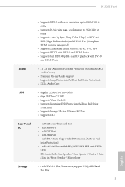
...; Supports Energy Efficient Ethernet 802.3az • Supports PXE Rear Panel I/O • 1 x PS/2 Mouse/Keyboard Port • 1 x D-Sub Port • 1 x DVI-D Port • 1 x HDMI Port • 4 x USB 3.0 Ports (Supports ESD Protection (ASRock Full Spike Protection)) • 1 x RJ-45 LAN Port with LED (ACT/LINK LED and SPEED LED) • HD Audio Jacks: Side Speaker / Rear Speaker / Central / Bass / Line in / Front Speaker / Microphone Storage • 6 x SATA3 6.0 Gb/s Connectors, support NCQ, AHCI and Hot Plug 3 English B150M Pro4 • Supports DVI-D with max.
...; Supports Energy Efficient Ethernet 802.3az • Supports PXE Rear Panel I/O • 1 x PS/2 Mouse/Keyboard Port • 1 x D-Sub Port • 1 x DVI-D Port • 1 x HDMI Port • 4 x USB 3.0 Ports (Supports ESD Protection (ASRock Full Spike Protection)) • 1 x RJ-45 LAN Port with LED (ACT/LINK LED and SPEED LED) • HD Audio Jacks: Side Speaker / Rear Speaker / Central / Bass / Line in / Front Speaker / Microphone Storage • 6 x SATA3 6.0 Gb/s Connectors, support NCQ, AHCI and Hot Plug 3 English B150M Pro4 • Supports DVI-D with max.

User Manual
Page 9
...8226; Voltage monitoring: +12V, +5V, +3.3V, CPU Vcore, GT_CPU, DRAM, VPPM, PCH 1.0V, VCCIO, VCCSA OS • Microsoft® Windows® 10 64-bit / 8.1 64-bit / 7 32-bit / 7 64- Connector • 1 x Print Port Header • 1 x COM Port Header • 1 x TPM Header • 1 x Chassis Intrusion and Speaker Header • 1 x CPU Fan Connector (4-pin) (Smart Fan Speed Control) • 2 x Chassis Fan Connectors (4-pin) (Smart Fan Speed Control) • 1 x 24 pin ATX Power Connector • 1 x 8 pin 12V Power Connector • 1 x Front Panel Audio Connector • 1 x USB 2.0 Header...
...8226; Voltage monitoring: +12V, +5V, +3.3V, CPU Vcore, GT_CPU, DRAM, VPPM, PCH 1.0V, VCCIO, VCCSA OS • Microsoft® Windows® 10 64-bit / 8.1 64-bit / 7 32-bit / 7 64- Connector • 1 x Print Port Header • 1 x COM Port Header • 1 x TPM Header • 1 x Chassis Intrusion and Speaker Header • 1 x CPU Fan Connector (4-pin) (Smart Fan Speed Control) • 2 x Chassis Fan Connectors (4-pin) (Smart Fan Speed Control) • 1 x 24 pin ATX Power Connector • 1 x 8 pin 12V Power Connector • 1 x Front Panel Audio Connector • 1 x USB 2.0 Header...

User Manual
Page 12
...DIMM Slots (DDR4_A2, DDR4_B2) 5 ATX Power Connector (ATXPWR1) 6 SATA3 Connector (SATA3_0) 7 SATA3 Connector (SATA3_1) 8 USB 3.0 Header (USB3_5_6) 9 Chassis Fan Connector (CHA_FAN2) 10 SATA3 Connector (SATA3_2) 11 SATA3 Connector (SATA3_3) 12 SATA3 Connector (SATA3_5) 13 SATA3 Connector (SATA3_4) 14 System Panel Header (PANEL1) 15 Chassis Intrusion and Speaker Header (SPK_CI1) 16 Clear CMOS Jumper (CLRMOS1) 17 USB 2.0 Header (USB1_2) 18 TPM Header (TPMS1) 19 Print Port Header (LPT1) 20 COM Port Header (COM1) 21 Front Panel Audio Header (HD_AUDIO1) 22 Chassis Fan Connector (CHA_FAN1) B150M Pro4...
...DIMM Slots (DDR4_A2, DDR4_B2) 5 ATX Power Connector (ATXPWR1) 6 SATA3 Connector (SATA3_0) 7 SATA3 Connector (SATA3_1) 8 USB 3.0 Header (USB3_5_6) 9 Chassis Fan Connector (CHA_FAN2) 10 SATA3 Connector (SATA3_2) 11 SATA3 Connector (SATA3_3) 12 SATA3 Connector (SATA3_5) 13 SATA3 Connector (SATA3_4) 14 System Panel Header (PANEL1) 15 Chassis Intrusion and Speaker Header (SPK_CI1) 16 Clear CMOS Jumper (CLRMOS1) 17 USB 2.0 Header (USB1_2) 18 TPM Header (TPMS1) 19 Print Port Header (LPT1) 20 COM Port Header (COM1) 21 Front Panel Audio Header (HD_AUDIO1) 22 Chassis Fan Connector (CHA_FAN1) B150M Pro4...

User Manual
Page 22
... power supply is switched off or the power cord is used for the card before you start the installation. PCIE2 (PCIe 3.0 x1 slot) is used for PCI Express x16 lane width graphics cards. PCIe Slot Configurations Single Graphics Card PCIE1 x16 PCIE4 N/A Two Graphics Cards in CrossFireXTM Mode x16 x4 For a better thermal environment, please connect a chassis fan to the motherboard's chassis fan connector (CHA_FAN1 or CHA_FAN2) when using multiple graphics cards. PCIE3 (PCIe 3.0 x1 slot) is used for PCI Express x4 lane width graphics cards. PCIE4 (PCIe 3.0 x16 slot) is used...
... power supply is switched off or the power cord is used for the card before you start the installation. PCIE2 (PCIe 3.0 x1 slot) is used for PCI Express x16 lane width graphics cards. PCIe Slot Configurations Single Graphics Card PCIE1 x16 PCIE4 N/A Two Graphics Cards in CrossFireXTM Mode x16 x4 For a better thermal environment, please connect a chassis fan to the motherboard's chassis fan connector (CHA_FAN1 or CHA_FAN2) when using multiple graphics cards. PCIE3 (PCIe 3.0 x1 slot) is used for PCI Express x4 lane width graphics cards. PCIE4 (PCIe 3.0 x16 slot) is used...

User Manual
Page 23
... the pins, the jumper is "Short". However, please do the clear-CMOS action. Please adjust the BIOS option "Clear Status" to default setup, please turn off the computer and unplug the power cord from the power supply. To clear and reset the system parameters to clear the record of previous chassis intrusion status. Please be noted that the password, date, time, and user default profile will be detected. If you update the BIOS...
... the pins, the jumper is "Short". However, please do the clear-CMOS action. Please adjust the BIOS option "Clear Status" to default setup, please turn off the computer and unplug the power cord from the power supply. To clear and reset the system parameters to clear the record of previous chassis intrusion status. Please be noted that the password, date, time, and user default profile will be detected. If you update the BIOS...

User Manual
Page 24
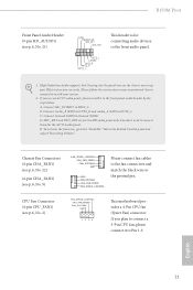
... front panel design may configure the way to this header, make sure the wire assignments and the pin assignments are NOT jumpers. System Panel Header (9-pin PANEL1) (see p.6, No. 14) PLED+ PLEDPWRBTN# GND 1 GND RESET# GND HDLEDHDLED+ Connect the power switch, reset switch and system status indicator on when the system is on the chassis to turn off (S5). B150M Pro4 2.6 Onboard Headers and Connectors Onboard headers and connectors are matched correctly. The LED is operating...
... front panel design may configure the way to this header, make sure the wire assignments and the pin assignments are NOT jumpers. System Panel Header (9-pin PANEL1) (see p.6, No. 14) PLED+ PLEDPWRBTN# GND 1 GND RESET# GND HDLEDHDLED+ Connect the power switch, reset switch and system status indicator on when the system is on the chassis to turn off (S5). B150M Pro4 2.6 Onboard Headers and Connectors Onboard headers and connectors are matched correctly. The LED is operating...
User Manual
Page 26
... MIC2_L. E. If you use an AC'97 audio panel, please install it to connect them for the HD audio panel only. Connect Mic_IN (MIC) to Ground (GND). CPU Fan Connector (4-pin CPU_FAN1) (see p.6, No. 2) FAN_SPEED_CONTROL CPU_FAN_SPEED FAN_VOLTAGE GND 1 2 34 This motherboard provides a 4-Pin CPU fan (Quiet Fan) connector. High Definition Audio supports Jack Sensing, but the panel wire on the chassis must support HDA to the "FrontMic" Tab in our manual and chassis manual to OUT2_L. To activate...
... MIC2_L. E. If you use an AC'97 audio panel, please install it to connect them for the HD audio panel only. Connect Mic_IN (MIC) to Ground (GND). CPU Fan Connector (4-pin CPU_FAN1) (see p.6, No. 2) FAN_SPEED_CONTROL CPU_FAN_SPEED FAN_VOLTAGE GND 1 2 34 This motherboard provides a 4-Pin CPU fan (Quiet Fan) connector. High Definition Audio supports Jack Sensing, but the panel wire on the chassis must support HDA to the "FrontMic" Tab in our manual and chassis manual to OUT2_L. To activate...
User Manual
Page 28
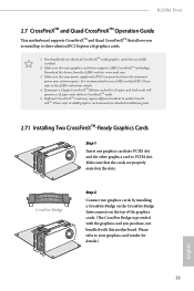
... the top of the graphics cards. (The CrossFire Bridge is recommended to AMD graphics card manuals for details. 4. You should only use a AMD certified PSU. CrossFire Bridge Step 2 Connect two graphics cards by installing a CrossFire Bridge on the CrossFire Bridge Interconnects on the slots. It is provided with the graphics card you to install up to enable CrossFireXTM. B150M Pro4 2.7 CrossFireXTM and Quad CrossFireXTM Operation Guide This motherboard supports CrossFireXTM and Quad...
... the top of the graphics cards. (The CrossFire Bridge is recommended to AMD graphics card manuals for details. 4. You should only use a AMD certified PSU. CrossFire Bridge Step 2 Connect two graphics cards by installing a CrossFire Bridge on the CrossFire Bridge Interconnects on the slots. It is provided with the graphics card you to install up to enable CrossFireXTM. B150M Pro4 2.7 CrossFireXTM and Quad CrossFireXTM Operation Guide This motherboard supports CrossFireXTM and Quad...
User Manual
Page 30
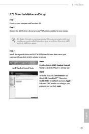
... optional download. Step 3 Install the required drivers and CATALYST Control Center then restart your graphics card and click Apply. Please check AMD's website for details. Step 2 Remove the AMD drivers if you have any previously installed Catalyst drivers prior to your computer. AMD Catalyst Control Center Step 4 Double-click the AMD Catalyst Control Center icon in your computer and boot into OS. English 25 Please check AMD's website for AMD driver updates. B150M Pro4 2.7.2 Driver Installation...
... optional download. Step 3 Install the required drivers and CATALYST Control Center then restart your graphics card and click Apply. Please check AMD's website for details. Step 2 Remove the AMD drivers if you have any previously installed Catalyst drivers prior to your computer. AMD Catalyst Control Center Step 4 Double-click the AMD Catalyst Control Center icon in your computer and boot into OS. English 25 Please check AMD's website for AMD driver updates. B150M Pro4 2.7.2 Driver Installation...
User Manual
Page 31
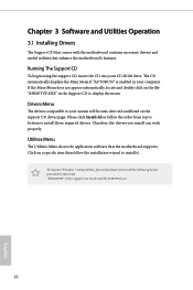
... displays the Main Menu if "AUTORUN" is enabled in the Support CD to install those required drivers. "KB2720599": http://support.microsoft.com/kb/2720599/en-us 26 English Please click Install All or follow the installation wizard to your system will be auto-detected and listed on the file "ASRSETUP.EXE" in your CD-ROM drive. Chapter 3 Software and Utilities Operation 3.1 Installing Drivers The Support CD that comes with the motherboard...
... displays the Main Menu if "AUTORUN" is enabled in the Support CD to install those required drivers. "KB2720599": http://support.microsoft.com/kb/2720599/en-us 26 English Please click Install All or follow the installation wizard to your system will be auto-detected and listed on the file "ASRSETUP.EXE" in your CD-ROM drive. Chapter 3 Software and Utilities Operation 3.1 Installing Drivers The Support CD that comes with the motherboard...
User Manual
Page 38
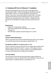
... UEFI SETUP UTILITY > Advanced > USB Configuration, which allows the USB port to install Windows 7 operating system because the USB ports on their support for the Enhanced Host Controller Interface (EHCI - B150M Pro4 3.3 Enabling USB Ports for Windows® 7 Installation Intel® Braswell and Skylake has removed their motherboard won't work. Due to that fact that XHCI is an optical disc drive but no PS/2 ports on your computer, please enable the "PS/2 Simulator" option in the Windows 7 inbox drivers, users...
... UEFI SETUP UTILITY > Advanced > USB Configuration, which allows the USB port to install Windows 7 operating system because the USB ports on their support for the Enhanced Host Controller Interface (EHCI - B150M Pro4 3.3 Enabling USB Ports for Windows® 7 Installation Intel® Braswell and Skylake has removed their motherboard won't work. Due to that fact that XHCI is an optical disc drive but no PS/2 ports on your computer, please enable the "PS/2 Simulator" option in the Windows 7 inbox drivers, users...
User Manual
Page 39
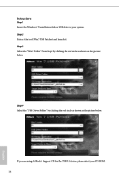
Step 2 Extract the tool (Win7 USB Patcher) and launch it. Step 4 Select the "USB Driver Folder" by clicking the red circle as shown as the picture below . Instructions Step 1 Insert the Windows® 7 installation disk or USB drive to your CD-ROM. 34 English If you are using ASRock's Support CD for the USB 3.0 driver, please select your system. Step 3 Select the "Win7 Folder" from Step1 by clicking the red circle as shown as the picture below .
Step 2 Extract the tool (Win7 USB Patcher) and launch it. Step 4 Select the "USB Driver Folder" by clicking the red circle as shown as the picture below . Instructions Step 1 Insert the Windows® 7 installation disk or USB drive to your CD-ROM. 34 English If you are using ASRock's Support CD for the USB 3.0 driver, please select your system. Step 3 Select the "Win7 Folder" from Step1 by clicking the red circle as shown as the picture below .

User Manual
Page 41
... to configure your screen. 4.1.1 UEFI Menu Bar The top of the screen has a menu bar with its test routines. Because the UEFI software is constantly being updated, the following selections: Main For setting system time/date information OC Tweaker For overclocking configurations Advanced For advanced system configurations Tool Useful tools H/W Monitor Displays current hardware status Boot For configuring boot settings and boot priority Security For security settings Exit Exit the current screen or the UEFI Setup Utility...
... to configure your screen. 4.1.1 UEFI Menu Bar The top of the screen has a menu bar with its test routines. Because the UEFI software is constantly being updated, the following selections: Main For setting system time/date information OC Tweaker For overclocking configurations Advanced For advanced system configurations Tool Useful tools H/W Monitor Displays current hardware status Boot For configuring boot settings and boot priority Security For security settings Exit Exit the current screen or the UEFI Setup Utility...

User Manual
Page 56
... external graphics card is idle for lower power consumption. Share Memory Configure the size of memory that is installed. Onboard HD Audio Enable/disable onboard HD audio. If [Power On] is on AC/Power Loss Select the power state after a power failure. Front Panel Enable/disable front panel HD audio. Good Night LED By enabling Good Night LED, the Power/HDD LEDs will be switched off when the system is selected, the system will start to the integrated graphics processor when the system boots up...
... external graphics card is idle for lower power consumption. Share Memory Configure the size of memory that is installed. Onboard HD Audio Enable/disable onboard HD audio. If [Power On] is on AC/Power Loss Select the power state after a power failure. Front Panel Enable/disable front panel HD audio. Good Night LED By enabling Good Night LED, the Power/HDD LEDs will be switched off when the system is selected, the system will start to the integrated graphics processor when the system boots up...

User Manual
Page 58
Serial Port Address Select the address of the Parallel port. Parallel Port Enable or disable the Parallel port. 4.4.4 Super IO Configuration B150M Pro4 Serial Port Enable or disable the Serial port. Device Mode Select the device mode according to Auto. 53 English Change Settings Select the address of the Serial port. PS2 Y-Cable Enable the PS2 Y-Cable or set this option to your connected device.
Serial Port Address Select the address of the Parallel port. Parallel Port Enable or disable the Parallel port. 4.4.4 Super IO Configuration B150M Pro4 Serial Port Enable or disable the Serial port. Device Mode Select the device mode according to Auto. 53 English Change Settings Select the address of the Serial port. PS2 Y-Cable Enable the PS2 Y-Cable or set this option to your connected device.
User Manual
Page 63
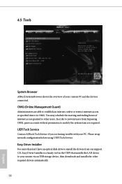
... Please setup network configuration before using UEFI Tech Service. OMG (Online Management Guard) Administrators are able to your system via OMG. Easy Driver Installer For users that installs the LAN driver to establish an internet curfew or restrict internet access at specified times via an USB storage device, then downloads and installs the other users. You may schedule the starting and ending hours of your PC. 4.5 Tools System Browser ASRock System...
... Please setup network configuration before using UEFI Tech Service. OMG (Online Management Guard) Administrators are able to your system via OMG. Easy Driver Installer For users that installs the LAN driver to establish an internet curfew or restrict internet access at specified times via an USB storage device, then downloads and installs the other users. You may schedule the starting and ending hours of your PC. 4.5 Tools System Browser ASRock System...
User Manual
Page 65
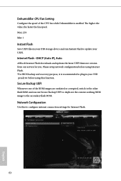
... (Auto IP), Auto ASRock Internet Flash downloads and updates the latest UEFI firmware version from our servers for Internet Flash. 60 English Dehumidifier CPU Fan Setting Configure the speed of the ROM images are outdated or corrupted, switch to the other flash ROM and execute Secure Backup UEFI to duplicate the current working ROM image to configure internet connection settings for you. Secure Backup UEFI Whenever one of the CPU fan while Dehumidifier is recommended to plug in your USB storage device...
... (Auto IP), Auto ASRock Internet Flash downloads and updates the latest UEFI firmware version from our servers for Internet Flash. 60 English Dehumidifier CPU Fan Setting Configure the speed of the ROM images are outdated or corrupted, switch to the other flash ROM and execute Secure Backup UEFI to duplicate the current working ROM image to configure internet connection settings for you. Secure Backup UEFI Whenever one of the CPU fan while Dehumidifier is recommended to plug in your USB storage device...

User Manual
Page 69
... may also clear the user password. User Password Set or change the settings in the UEFI Setup Utility. Users are unable to change the password for the system. Leave it blank and press enter to remove the password. Supervisor Password Set or change the settings in ME. 4.7 Security Screen In this option to use discrete TPM Module. 64 English Secure Boot Use this item to change the password for Windows 8.1 Secure Boot. Only the administrator has authority to enable or disable support for...
... may also clear the user password. User Password Set or change the settings in the UEFI Setup Utility. Users are unable to change the password for the system. Leave it blank and press enter to remove the password. Supervisor Password Set or change the settings in ME. 4.7 Security Screen In this option to use discrete TPM Module. 64 English Secure Boot Use this item to change the password for Windows 8.1 Secure Boot. Only the administrator has authority to enable or disable support for...


