
User Manual
Page 4
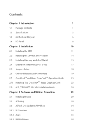
... 23 2.7.1 Installing Two CrossFireXTM-Ready Graphics Cards 23 2.8 M.2_SSD (NGFF) Module Installation Guide 26 Chapter 3 Software and Utilities Operation 29 3.1 Installing Drivers 29 3.2 A-Tuning 30 3.3 ASRock Live Update & APP Shop 34 3.3.1 UI Overview 34 3.3.2 Apps 35...
... 23 2.7.1 Installing Two CrossFireXTM-Ready Graphics Cards 23 2.8 M.2_SSD (NGFF) Module Installation Guide 26 Chapter 3 Software and Utilities Operation 29 3.1 Installing Drivers 29 3.2 A-Tuning 30 3.3 ASRock Live Update & APP Shop 34 3.3.1 UI Overview 34 3.3.2 Apps 35...

User Manual
Page 6
.... Chapter 4 contains the configuration guide of the software and utilities. If you for purchasing ASRock B150A-X1/Hyper motherboard, a reliable motherboard produced under ASRock's consistently stringent quality control. Chapter 3 contains the operation guide of the BIOS setup. Because the motherboard specifications and the BIOS software might be updated, the content of this documentation, Chapter 1 and 2 contains the...
.... Chapter 4 contains the configuration guide of the software and utilities. If you for purchasing ASRock B150A-X1/Hyper motherboard, a reliable motherboard produced under ASRock's consistently stringent quality control. Chapter 3 contains the operation guide of the BIOS setup. Because the motherboard specifications and the BIOS software might be updated, the content of this documentation, Chapter 1 and 2 contains the...
User Manual
Page 9
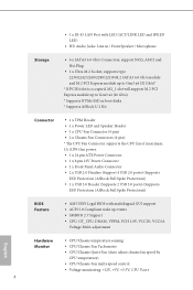
...slot is occupied, M2_1 slot will support M.2 PCI Express module up to Gen3 x2 (16 Gb/s). * Supports NVMe SSD as boot disks * Supports ASRock U.2 Kit Connector • 1 x TPM Header • 1 x Power LED and Speaker Header • 1 x CPU Fan Connector (4-pin) ... x USB 2.0 Headers (Support 4 USB 2.0 ports) (Supports ESD Protection (ASRock Full Spike Protection)) • 1 x USB 3.0 Header (Supports 2 USB 3.0 ports) (Supports ESD Protection (ASRock Full Spike Protection)) BIOS Feature • AMI UEFI Legal BIOS with multilingual GUI support • ACPI 5.0 Compliant wake up events • ...
...slot is occupied, M2_1 slot will support M.2 PCI Express module up to Gen3 x2 (16 Gb/s). * Supports NVMe SSD as boot disks * Supports ASRock U.2 Kit Connector • 1 x TPM Header • 1 x Power LED and Speaker Header • 1 x CPU Fan Connector (4-pin) ... x USB 2.0 Headers (Support 4 USB 2.0 ports) (Supports ESD Protection (ASRock Full Spike Protection)) • 1 x USB 3.0 Header (Supports 2 USB 3.0 ports) (Supports ESD Protection (ASRock Full Spike Protection)) BIOS Feature • AMI UEFI Legal BIOS with multilingual GUI support • ACPI 5.0 Compliant wake up events • ...
User Manual
Page 10
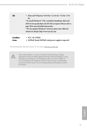
... detailed product information, please visit our website: http://www.asrock.com Please realize that there is required. Please refer to the components and devices of your own risk and expense. English 5 B150A-X1/Hyper OS Certifications • Microsoft® Windows® 10 ...64-bit / 8.1 64-bit / 7 32-bit / 7 64bit * To install Windows® 7 OS, a modified installation disk with xHCI drivers packed into the ISO file is a certain risk involved with overclocking, including adjusting the setting in the BIOS...
... detailed product information, please visit our website: http://www.asrock.com Please realize that there is required. Please refer to the components and devices of your own risk and expense. English 5 B150A-X1/Hyper OS Certifications • Microsoft® Windows® 10 ...64-bit / 8.1 64-bit / 7 32-bit / 7 64bit * To install Windows® 7 OS, a modified installation disk with xHCI drivers packed into the ISO file is a certain risk involved with overclocking, including adjusting the setting in the BIOS...
User Manual
Page 11
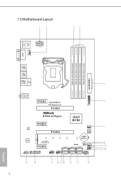
... B: USB3 USB 2.0 T: USB0 Top: B: USB1 RJ-45 5 Top: LINE IN Center: FRONT Bottom: MIC IN PCIE1 Front USB 3.0 PCI Express 3.0 PCIE2 1 6 USB3_4_5 B150A-X1/Hyper Intel B150 PCIE3 LAN 7 CHA_FAN1 PCIE4 BIOS ROM AUDIO CODEC HD_AUDIO1 1 M2_1 CT1 CT2 CT3 Ultra M.2 PCIe Gen3 x4 PCIE5 TPMS1 1 USB4_5 1 USB2_3 1 CT4 SATA3_4 SATA3_5 CMOS Battery CT5...
... B: USB3 USB 2.0 T: USB0 Top: B: USB1 RJ-45 5 Top: LINE IN Center: FRONT Bottom: MIC IN PCIE1 Front USB 3.0 PCI Express 3.0 PCIE2 1 6 USB3_4_5 B150A-X1/Hyper Intel B150 PCIE3 LAN 7 CHA_FAN1 PCIE4 BIOS ROM AUDIO CODEC HD_AUDIO1 1 M2_1 CT1 CT2 CT3 Ultra M.2 PCIe Gen3 x4 PCIE5 TPMS1 1 USB4_5 1 USB2_3 1 CT4 SATA3_4 SATA3_5 CMOS Battery CT5...
User Manual
Page 23
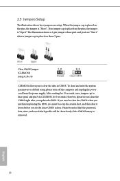
Clear CMOS Jumper (CLRMOS1) (see p.6, No. 8) Default Clear CMOS CLRMOS1 allows you update the BIOS. However, please do the clear-CMOS action. Please be noted that the password, date, time, and user default profile will be cleared only if the ... The illustration shows how jumpers are "Short" when a jumper cap is removed. If you need to clear the CMOS when you just finish updating the BIOS, you must boot up the system first, and then shut it down before you do not clear the CMOS right after you to clear the...
Clear CMOS Jumper (CLRMOS1) (see p.6, No. 8) Default Clear CMOS CLRMOS1 allows you update the BIOS. However, please do the clear-CMOS action. Please be noted that the password, date, time, and user default profile will be cleared only if the ... The illustration shows how jumpers are "Short" when a jumper cap is removed. If you need to clear the CMOS when you just finish updating the BIOS, you must boot up the system first, and then shut it down before you do not clear the CMOS right after you to clear the...
User Manual
Page 43
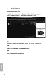
Step 1 Please check the item information before update. Please update them all soon. Click to select one or more items you will see more details. Step 3 Click Update to update. Click on Step 2 to see a list of recommended or critical updates for the BIOS or drivers. 3.3.3 BIOS & Drivers Installing BIOS or Drivers When the "BIOS & Drivers" tab is selected, you want to start the update process. 38 English
Step 1 Please check the item information before update. Please update them all soon. Click to select one or more items you will see more details. Step 3 Click Update to update. Click on Step 2 to see a list of recommended or critical updates for the BIOS or drivers. 3.3.3 BIOS & Drivers Installing BIOS or Drivers When the "BIOS & Drivers" tab is selected, you want to start the update process. 38 English

User Manual
Page 49
... the upper right corner of the screen to switch to Advanced Mode 44 English 4.2 EZ Mode The EZ Mode screen appears when you enter the BIOS setup program by default.
... the upper right corner of the screen to switch to Advanced Mode 44 English 4.2 EZ Mode The EZ Mode screen appears when you enter the BIOS setup program by default.
User Manual
Page 50
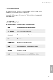
B150A-X1/Hyper 4.3 Advanced Mode The Advanced Mode provides more options to the following selections: Main For setting system time/date information OC Tweaker For overclocking configurations Advanced ... boot settings and boot priority Security For security settings Exit Exit the current screen or the UEFI Setup Utility English 45 Refer to configure the BIOS settings. To access the EZ Mode, press or click the "EZ Mode" button at the upper right corner of the screen. 4.3.1 UEFI Menu Bar The...
B150A-X1/Hyper 4.3 Advanced Mode The Advanced Mode provides more options to the following selections: Main For setting system time/date information OC Tweaker For overclocking configurations Advanced ... boot settings and boot priority Security For security settings Exit Exit the current screen or the UEFI Setup Utility English 45 Refer to configure the BIOS settings. To access the EZ Mode, press or click the "EZ Mode" button at the upper right corner of the screen. 4.3.1 UEFI Menu Bar The...
User Manual
Page 52
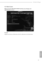
B150A-X1/Hyper 4.4 Main Screen When you enter the UEFI SETUP UTILITY, the Main screen will appear and display the system overview. Favorite Display your collection of BIOS items. Press F5 to add/remove your favorite items. 47 English
B150A-X1/Hyper 4.4 Main Screen When you enter the UEFI SETUP UTILITY, the Main screen will appear and display the system overview. Favorite Display your collection of BIOS items. Press F5 to add/remove your favorite items. 47 English
User Manual
Page 53
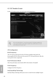
4.5 OC Tweaker Screen In the OC Tweaker screen, you see on your screen. Boot Performance Mode Select the performance state that the BIOS will increase the internal CPU clock speed but also affect the clock speed of other components. FCLK Frequency Configure the FCLK Frequency. Increasing the BCLK ...
4.5 OC Tweaker Screen In the OC Tweaker screen, you see on your screen. Boot Performance Mode Select the performance state that the BIOS will increase the internal CPU clock speed but also affect the clock speed of other components. FCLK Frequency Configure the FCLK Frequency. Increasing the BCLK ...

User Manual
Page 71
Timeout Seconds Configure the number of seconds to update your UEFI. DHCP (Auto IP), Auto ASRock Internet Flash downloads and updates the latest UEFI firmware version from our servers for the Boot Manager. Boot Manager Timeout Enable/disable the Boot Manager ... devices to plug in your USB storage device and run Instant Flash to wait for you. Please setup network configuration before using Internet Flash. *For BIOS backup and recovery purpose, it is recommended to use this function. 66 English Boot Manager Enable/disable the Boot Manager. Internet Flash -
Timeout Seconds Configure the number of seconds to update your UEFI. DHCP (Auto IP), Auto ASRock Internet Flash downloads and updates the latest UEFI firmware version from our servers for the Boot Manager. Boot Manager Timeout Enable/disable the Boot Manager ... devices to plug in your USB storage device and run Instant Flash to wait for you. Please setup network configuration before using Internet Flash. *For BIOS backup and recovery purpose, it is recommended to use this function. 66 English Boot Manager Enable/disable the Boot Manager. Internet Flash -


