
User Manual
Page 4
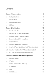
... 1.2 Specifications 2 1.3 Motherboard Layout 6 1.4 I/O Panel 8 Chapter 2 Installation 10 2.1 Installing the CPU 11 2.2 Installing the CPU Fan and Heatsink 14 2.3 Installing Memory Modules (DIMM) 15 2.4 Expansion Slots (PCI Express Slots) 17 2.5 Jumpers Setup 18 2.6 Onboard Headers and Connectors 19 2.7 CrossFireXTM and Quad CrossFireXTM Operation Guide 23 2.7.1 Installing Two CrossFireXTM-Ready Graphics Cards 23 2.8 M.2_SSD (NGFF) Module Installation Guide 26 Chapter 3 Software and Utilities Operation 29 3.1 Installing Drivers 29 3.2 A-Tuning 30 3.3 ASRock Live...
... 1.2 Specifications 2 1.3 Motherboard Layout 6 1.4 I/O Panel 8 Chapter 2 Installation 10 2.1 Installing the CPU 11 2.2 Installing the CPU Fan and Heatsink 14 2.3 Installing Memory Modules (DIMM) 15 2.4 Expansion Slots (PCI Express Slots) 17 2.5 Jumpers Setup 18 2.6 Onboard Headers and Connectors 19 2.7 CrossFireXTM and Quad CrossFireXTM Operation Guide 23 2.7.1 Installing Two CrossFireXTM-Ready Graphics Cards 23 2.8 M.2_SSD (NGFF) Module Installation Guide 26 Chapter 3 Software and Utilities Operation 29 3.1 Installing Drivers 29 3.2 A-Tuning 30 3.3 ASRock Live...

User Manual
Page 6
... • ASRock B150A-X1/Hyper Motherboard (ATX Form Factor) • ASRock B150A-X1/Hyper Quick Installation Guide • ASRock B150A-X1/Hyper Support CD • 2 x Serial ATA (SATA) Data Cables (Optional) • 1 x I/O Panel Shield • 1 x Screw for purchasing ASRock B150A-X1/Hyper motherboard, a reliable motherboard produced under ASRock's consistently stringent quality control. It delivers excellent performance with robust design conforming to ASRock's commitment to change without further notice. You may find the latest VGA cards and CPU support list on ASRock's website...
... • ASRock B150A-X1/Hyper Motherboard (ATX Form Factor) • ASRock B150A-X1/Hyper Quick Installation Guide • ASRock B150A-X1/Hyper Support CD • 2 x Serial ATA (SATA) Data Cables (Optional) • 1 x I/O Panel Shield • 1 x Screw for purchasing ASRock B150A-X1/Hyper motherboard, a reliable motherboard produced under ASRock's consistently stringent quality control. It delivers excellent performance with robust design conforming to ASRock's commitment to change without further notice. You may find the latest VGA cards and CPU support list on ASRock's website...
User Manual
Page 8
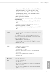
... • Supports Wake-On-LAN • Supports Lightning/ESD Protection (ASRock Full Spike Protection) • Supports Energy Efficient Ethernet 802.3az • Supports PXE Rear Panel I/O • 1 x PS/2 Mouse Port • 1 x PS/2 Keyboard Port • 1 x DVI-D Port • 2 x USB 2.0 Ports (Supports ESD Protection (ASRock Full Spike Protection)) • 4 x USB 3.0 Ports (Supports ESD Protection (ASRock Full Spike Protection)) 3 English B150A-X1/Hyper • Supports Intel® HD Graphics Built-in Visuals : Intel® Quick Sync Video with...
... • Supports Wake-On-LAN • Supports Lightning/ESD Protection (ASRock Full Spike Protection) • Supports Energy Efficient Ethernet 802.3az • Supports PXE Rear Panel I/O • 1 x PS/2 Mouse Port • 1 x PS/2 Keyboard Port • 1 x DVI-D Port • 2 x USB 2.0 Ports (Supports ESD Protection (ASRock Full Spike Protection)) • 4 x USB 3.0 Ports (Supports ESD Protection (ASRock Full Spike Protection)) 3 English B150A-X1/Hyper • Supports Intel® HD Graphics Built-in Visuals : Intel® Quick Sync Video with...
User Manual
Page 9
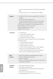
... If PCIE4 slot is occupied, M2_1 slot will support M.2 PCI Express module up to Gen3 x2 (16 Gb/s). * Supports NVMe SSD as boot disks * Supports ASRock U.2 Kit Connector • 1 x TPM Header • 1 x Power LED and Speaker Header • 1 x CPU Fan Connector (4-pin) • 2 x Chassis Fan Connectors (4-pin) * The CPU Fan Connector supports the CPU fan of maximum 1A (12W) fan power. • 1 x 24 pin ATX Power Connector • 1 x 8 pin 12V Power Connector • 1 x Front Panel Audio Connector • 2 x USB 2.0 Headers (Support 4 USB 2.0 ports) (Supports ESD Protection (ASRock Full...
... If PCIE4 slot is occupied, M2_1 slot will support M.2 PCI Express module up to Gen3 x2 (16 Gb/s). * Supports NVMe SSD as boot disks * Supports ASRock U.2 Kit Connector • 1 x TPM Header • 1 x Power LED and Speaker Header • 1 x CPU Fan Connector (4-pin) • 2 x Chassis Fan Connectors (4-pin) * The CPU Fan Connector supports the CPU fan of maximum 1A (12W) fan power. • 1 x 24 pin ATX Power Connector • 1 x 8 pin 12V Power Connector • 1 x Front Panel Audio Connector • 2 x USB 2.0 Headers (Support 4 USB 2.0 ports) (Supports ESD Protection (ASRock Full...
User Manual
Page 10
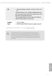
... ISO file is required. English 5 B150A-X1/Hyper OS Certifications • Microsoft® Windows® 10 64-bit / 8.1 64-bit / 7 32-bit / 7 64bit * To install Windows® 7 OS, a modified installation disk with overclocking, including adjusting the setting in the BIOS, applying Untied Overclocking Technology, or using third-party overclocking tools. Overclocking may affect your system's stability, or even cause damage to page 40 for more detailed instructions. * For the updated Windows® 10 driver...
... ISO file is required. English 5 B150A-X1/Hyper OS Certifications • Microsoft® Windows® 10 64-bit / 8.1 64-bit / 7 32-bit / 7 64bit * To install Windows® 7 OS, a modified installation disk with overclocking, including adjusting the setting in the BIOS, applying Untied Overclocking Technology, or using third-party overclocking tools. Overclocking may affect your system's stability, or even cause damage to page 40 for more detailed instructions. * For the updated Windows® 10 driver...
User Manual
Page 11
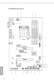
1.3 Motherboard Layout 1 2 34 PS2 Mouse PS2 Keyboard DDR4_A1 (64 bit, 288-pin module) DDR4_A2 (64 bit, 288-pin module) DDR4_B1 (64 bit, 288-pin module) DDR4_B2 (64 bit, 288-pin module) ATXPWR1 ATX12V1 CPU_FAN1 DVI1 USB 3.0 T: USB0 B: USB1 USB 3.0 T: USB2 B: USB3 USB 2.0 T: USB0 Top: B: USB1 RJ-45 5 Top: LINE IN Center: FRONT Bottom: MIC IN PCIE1 Front USB 3.0 PCI Express 3.0 PCIE2 1 6 USB3_4_5 B150A-X1/Hyper Intel B150 PCIE3 LAN 7 CHA_FAN1 PCIE4 BIOS ROM AUDIO CODEC...
1.3 Motherboard Layout 1 2 34 PS2 Mouse PS2 Keyboard DDR4_A1 (64 bit, 288-pin module) DDR4_A2 (64 bit, 288-pin module) DDR4_B1 (64 bit, 288-pin module) DDR4_B2 (64 bit, 288-pin module) ATXPWR1 ATX12V1 CPU_FAN1 DVI1 USB 3.0 T: USB0 B: USB1 USB 3.0 T: USB2 B: USB3 USB 2.0 T: USB0 Top: B: USB1 RJ-45 5 Top: LINE IN Center: FRONT Bottom: MIC IN PCIE1 Front USB 3.0 PCI Express 3.0 PCIE2 1 6 USB3_4_5 B150A-X1/Hyper Intel B150 PCIE3 LAN 7 CHA_FAN1 PCIE4 BIOS ROM AUDIO CODEC...
User Manual
Page 12
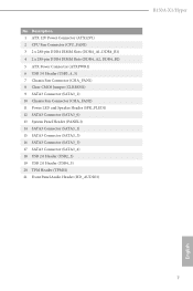
... 288-pin DDR4 DIMM Slots (DDR4_A2, DDR4_B2) 5 ATX Power Connector (ATXPWR1) 6 USB 3.0 Header (USB3_4_5) 7 Chassis Fan Connector (CHA_FAN1) 8 Clear CMOS Jumper (CLRMOS1) 9 SATA3 Connector (SATA3_2) 10 Chassis Fan Connector (CHA_FAN2) 11 Power LED and Speaker Header (SPK_PLED1) 12 SATA3 Connector (SATA3_0) 13 System Panel Header (PANEL1) 14 SATA3 Connector (SATA3_1) 15 SATA3 Connector (SATA3_3) 16 SATA3 Connector (SATA3_5) 17 SATA3 Connector (SATA3_4) 18 USB 2.0 Header (USB2_3) 19 USB 2.0 Header (USB4_5) 20 TPM Header (TPMS1) 21 Front Panel Audio Header (HD_AUDIO1) B150A-X1/Hyper English 7 No...
... 288-pin DDR4 DIMM Slots (DDR4_A2, DDR4_B2) 5 ATX Power Connector (ATXPWR1) 6 USB 3.0 Header (USB3_4_5) 7 Chassis Fan Connector (CHA_FAN1) 8 Clear CMOS Jumper (CLRMOS1) 9 SATA3 Connector (SATA3_2) 10 Chassis Fan Connector (CHA_FAN2) 11 Power LED and Speaker Header (SPK_PLED1) 12 SATA3 Connector (SATA3_0) 13 System Panel Header (PANEL1) 14 SATA3 Connector (SATA3_1) 15 SATA3 Connector (SATA3_3) 16 SATA3 Connector (SATA3_5) 17 SATA3 Connector (SATA3_4) 18 USB 2.0 Header (USB2_3) 19 USB 2.0 Header (USB4_5) 20 TPM Header (TPMS1) 21 Front Panel Audio Header (HD_AUDIO1) B150A-X1/Hyper English 7 No...
User Manual
Page 22
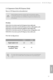
... B150A-X1/Hyper 2.4 Expansion Slots (PCI Express Slots) There are 5 PCI Express slots on the motherboard. Please read the documentation of the expansion card and make sure that the power supply is switched off or the power cord is used for PCI Express x1 lane width cards. PCIe Slot Configurations Single Graphics Card Two Graphics Cards in CrossFireXTM Mode PCIE2 x16 x16 PCIE4 N/A x4 For a better thermal environment, please connect a chassis fan to the motherboard's chassis fan connector (CHA_FAN1 or CHA_FAN2) when using multiple graphics cards. Before installing an expansion card...
... B150A-X1/Hyper 2.4 Expansion Slots (PCI Express Slots) There are 5 PCI Express slots on the motherboard. Please read the documentation of the expansion card and make sure that the power supply is switched off or the power cord is used for PCI Express x1 lane width cards. PCIe Slot Configurations Single Graphics Card Two Graphics Cards in CrossFireXTM Mode PCIE2 x16 x16 PCIE4 N/A x4 For a better thermal environment, please connect a chassis fan to the motherboard's chassis fan connector (CHA_FAN1 or CHA_FAN2) when using multiple graphics cards. Before installing an expansion card...
User Manual
Page 24
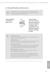
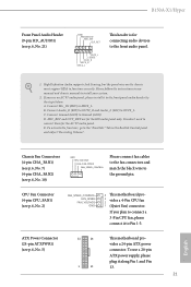
... the system is on the chassis front panel. When connecting your system using the power switch. A front panel module mainly consists of power switch, reset switch, power LED, hard drive activity LED, speaker and etc. PLED (System Power LED): Connect to this header according to the reset switch on when the hard drive is in S4 sleep state or powered off your chassis front panel module to the power status indicator on the chassis front panel. B150A-X1/Hyper 2.6 Onboard Headers and Connectors Onboard headers and connectors are matched correctly. You may...
... the system is on the chassis front panel. When connecting your system using the power switch. A front panel module mainly consists of power switch, reset switch, power LED, hard drive activity LED, speaker and etc. PLED (System Power LED): Connect to this header according to the reset switch on when the hard drive is in S4 sleep state or powered off your chassis front panel module to the power status indicator on the chassis front panel. B150A-X1/Hyper 2.6 Onboard Headers and Connectors Onboard headers and connectors are matched correctly. You may...
User Manual
Page 26
... audio header by the steps below: A. Connect Ground (GND) to MIC2_L. ATX Power Connector (24-pin ATXPWR1) (see p.6, No. 2) FAN_SPEED_CONTROL FAN_SPEED FAN_VOLTAGE GND 4 This motherboard pro- 3 2 vides a 4-Pin CPU fan 1 (Quiet Fan) connector. MIC_RET and OUT_RET are for the AC'97 audio panel. Chassis Fan Connectors (4-pin CHA_FAN1) (see p.6, No. 7) (4-pin CHA_FAN2) (see p.6, No. 21) GND PRESENCE# MIC_RET OUT_RET 1 OUT2_L J_SENSE OUT2_R MIC2_R MIC2_L This header is for connecting audio devices to the front audio panel. 1. B150A-X1/Hyper Front Panel Audio Header (9-pin...
... audio header by the steps below: A. Connect Ground (GND) to MIC2_L. ATX Power Connector (24-pin ATXPWR1) (see p.6, No. 2) FAN_SPEED_CONTROL FAN_SPEED FAN_VOLTAGE GND 4 This motherboard pro- 3 2 vides a 4-Pin CPU fan 1 (Quiet Fan) connector. MIC_RET and OUT_RET are for the AC'97 audio panel. Chassis Fan Connectors (4-pin CHA_FAN1) (see p.6, No. 7) (4-pin CHA_FAN2) (see p.6, No. 21) GND PRESENCE# MIC_RET OUT_RET 1 OUT2_L J_SENSE OUT2_R MIC2_R MIC2_L This header is for connecting audio devices to the front audio panel. 1. B150A-X1/Hyper Front Panel Audio Header (9-pin...
User Manual
Page 28
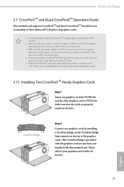
... cards are AMD certified. 2. B150A-X1/Hyper 2.7 CrossFireXTM and Quad CrossFireXTM Operation Guide This motherboard supports CrossFireXTM and Quad CrossFireXTM that allows you to install up to use identical CrossFireXTM-ready graphics cards that are properly seated on the top of the graphics cards. (The CrossFire Bridge is recommended to three identical PCI Express x16 graphics cards. 1. Different CrossFireXTM cards may require different methods to PCIE4 slot. Download the drivers from the AMD...
... cards are AMD certified. 2. B150A-X1/Hyper 2.7 CrossFireXTM and Quad CrossFireXTM Operation Guide This motherboard supports CrossFireXTM and Quad CrossFireXTM that allows you to install up to use identical CrossFireXTM-ready graphics cards that are properly seated on the top of the graphics cards. (The CrossFire Bridge is recommended to three identical PCI Express x16 graphics cards. 1. Different CrossFireXTM cards may require different methods to PCIE4 slot. Download the drivers from the AMD...

User Manual
Page 30
.... Step 3 Install the required drivers and CATALYST Control Center then restart your computer and boot into OS. Please check AMD's website for AMD driver updates. Select the GPU number according to installation. Step 5 In the left pane, click Performance and then AMD CrossFireXTM. English 25 B150A-X1/Hyper 2.7.2 Driver Installation and Setup Step 1 Power on your computer. Please check AMD's website for details. The Catalyst Uninstaller is an optional download.
.... Step 3 Install the required drivers and CATALYST Control Center then restart your computer and boot into OS. Please check AMD's website for AMD driver updates. Select the GPU number according to installation. Step 5 In the left pane, click Performance and then AMD CrossFireXTM. English 25 B150A-X1/Hyper 2.7.2 Driver Installation and Setup Step 1 Power on your computer. Please check AMD's website for details. The Catalyst Uninstaller is an optional download.
User Manual
Page 34
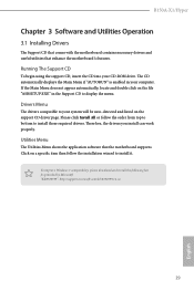
... enhance the motherboard's features. B150A-X1/Hyper Chapter 3 Software and Utilities Operation 3.1 Installing Drivers The Support CD that comes with the motherboard contains necessary drivers and useful utilities that the motherboard supports. Please click Install All or follow the installation wizard to install it. The CD automatically displays the Main Menu if "AUTORUN" is enabled in the Support CD to install those required drivers. Drivers Menu The drivers compatible to your system will be auto-detected and listed on a specific item then...
... enhance the motherboard's features. B150A-X1/Hyper Chapter 3 Software and Utilities Operation 3.1 Installing Drivers The Support CD that comes with the motherboard contains necessary drivers and useful utilities that the motherboard supports. Please click Install All or follow the installation wizard to install it. The CD automatically displays the Main Menu if "AUTORUN" is enabled in the Support CD to install those required drivers. Drivers Menu The drivers compatible to your system will be auto-detected and listed on a specific item then...
User Manual
Page 45
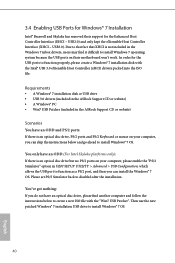
... ASRock Support CD or website) Scenarios You have an ODD (For Intel Skylake platforms only): If there is an optical disc drive, PS/2 ports and PS/2 Keyboard or mouse on your computer, please enable the "PS/2 Simulator" option in the Windows 7 inbox drivers, users may find another computer and follow the instructions below and go ahead to install Windows 7 operating system because the USB ports...
... ASRock Support CD or website) Scenarios You have an ODD (For Intel Skylake platforms only): If there is an optical disc drive, PS/2 ports and PS/2 Keyboard or mouse on your computer, please enable the "PS/2 Simulator" option in the Windows 7 inbox drivers, users may find another computer and follow the instructions below and go ahead to install Windows 7 operating system because the USB ports...
User Manual
Page 46
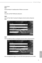
If you are using ASRock's Support CD for the USB 3.0 driver, please select your system. Step 4 Select the "USB Driver Folder" by clicking the red circle as shown as the picture below . Step 3 Select the "Win7 Folder" from Step1 by clicking the red circle as shown as the picture below . B150A-X1/Hyper Instructions Step 1 Insert the Windows® 7 installation disk or USB drive to your CD-ROM. 41 English Step 2 Extract the tool (Win7 USB Patcher) and launch it.
If you are using ASRock's Support CD for the USB 3.0 driver, please select your system. Step 4 Select the "USB Driver Folder" by clicking the red circle as shown as the picture below . Step 3 Select the "Win7 Folder" from Step1 by clicking the red circle as shown as the picture below . B150A-X1/Hyper Instructions Step 1 Insert the Windows® 7 installation disk or USB drive to your CD-ROM. 41 English Step 2 Extract the tool (Win7 USB Patcher) and launch it.
User Manual
Page 65
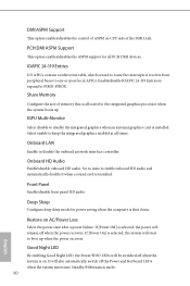
... enable to keep the integrated graphics enabled at all PCH DMI devices. Onboard LAN Enable or disable the onboard network interface controller. Front Panel Enable/disable front panel HD audio. Good Night LED By enabling Good Night LED, the Power/HDD LEDs will be switched off when the system is selected, the power will remain off the Power and Keyboard LEDs when the system enters into Standby/Hibernation mode. 60 English Set to Auto to enable onboard HD audio and automatically disable it when a sound card is used...
... enable to keep the integrated graphics enabled at all PCH DMI devices. Onboard LAN Enable or disable the onboard network interface controller. Front Panel Enable/disable front panel HD audio. Good Night LED By enabling Good Night LED, the Power/HDD LEDs will be switched off when the system is selected, the power will remain off the Power and Keyboard LEDs when the system enters into Standby/Hibernation mode. 60 English Set to Auto to enable onboard HD audio and automatically disable it when a sound card is used...
User Manual
Page 70
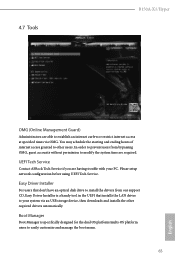
... your PC. Please setup network configuration before using UEFI Tech Service. You may schedule the starting and ending hours of internet access granted to easily customize and manage the boot menu. 65 English Boot Manager Boot Manager is a handy tool in the UEFI that installs the LAN driver to modify the system time are required. 4.7 Tools B150A-X1/Hyper OMG (Online Management Guard) Administrators are having trouble with your system...
... your PC. Please setup network configuration before using UEFI Tech Service. You may schedule the starting and ending hours of internet access granted to easily customize and manage the boot menu. 65 English Boot Manager Boot Manager is a handy tool in the UEFI that installs the LAN driver to modify the system time are required. 4.7 Tools B150A-X1/Hyper OMG (Online Management Guard) Administrators are having trouble with your system...

User Manual
Page 71
... setup network configuration before using Internet Flash. *For BIOS backup and recovery purpose, it is recommended to update your USB pen drive before using this tool. Instant Flash Save UEFI files in your USB storage device and run Instant Flash to plug in your UEFI. DHCP (Auto IP), Auto ASRock Internet Flash downloads and updates the latest UEFI firmware version from our servers for the Boot Manager. *Please connect more than one boot devices to wait for you. Boot Manager Timeout Enable/disable the Boot Manager Timeout. Boot...
... setup network configuration before using Internet Flash. *For BIOS backup and recovery purpose, it is recommended to update your USB pen drive before using this tool. Instant Flash Save UEFI files in your USB storage device and run Instant Flash to plug in your UEFI. DHCP (Auto IP), Auto ASRock Internet Flash downloads and updates the latest UEFI firmware version from our servers for the Boot Manager. *Please connect more than one boot devices to wait for you. Boot Manager Timeout Enable/disable the Boot Manager Timeout. Boot...
User Manual
Page 72
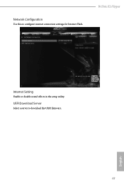
English 67 UEFI Download Server Select a server to configure internet connection settings for Internet Flash. B150A-X1/Hyper Internet Setting Enable or disable sound effects in the setup utility. Network Configuration Use this to download the UEFI firmware.
English 67 UEFI Download Server Select a server to configure internet connection settings for Internet Flash. B150A-X1/Hyper Internet Setting Enable or disable sound effects in the setup utility. Network Configuration Use this to download the UEFI firmware.
User Manual
Page 75
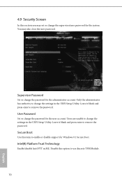
... press enter to enable or disable support for the system. Disable this option to remove the password. Supervisor Password Set or change the password for the user account. Users are unable to change the password for the administrator account. Intel(R) Platform Trust Technology Enable/disable Intel PTT in the UEFI Setup Utility. User Password Set or change the settings in the UEFI Setup Utility. Only the administrator has authority to change the supervisor/user password for Windows 8.1 Secure Boot. Leave it blank and press enter to use...
... press enter to enable or disable support for the system. Disable this option to remove the password. Supervisor Password Set or change the password for the user account. Users are unable to change the password for the administrator account. Intel(R) Platform Trust Technology Enable/disable Intel PTT in the UEFI Setup Utility. User Password Set or change the settings in the UEFI Setup Utility. Only the administrator has authority to change the supervisor/user password for Windows 8.1 Secure Boot. Leave it blank and press enter to use...


