
User Manual
Page 4
... I/O Panel 8 Chapter 2 Installation 10 2.1 Installing the CPU 11 2.2 Installing the CPU Fan and Heatsink 14 2.3 Installing Memory Modules (DIMM) 15 2.4 Expansion Slots (PCI and PCI Express Slots) 17 2.5 Jumpers Setup 18 2.6 Onboard Headers and Connectors 19 2.7 CrossFireXTM and Quad CrossFireXTM Operation Guide 23 2.7.1 Installing Two CrossFireXTM-Ready Graphics Cards 23 2.7.2 Driver Installation and Setup 25 Chapter 3 Software and Utilities Operation 26 3.1 Installing Drivers 26 3.2 ASRock Live Update & APP Shop 27 3.2.1 UI Overview 27 3.2.2 Apps 28 3.2.3 BIOS...
... I/O Panel 8 Chapter 2 Installation 10 2.1 Installing the CPU 11 2.2 Installing the CPU Fan and Heatsink 14 2.3 Installing Memory Modules (DIMM) 15 2.4 Expansion Slots (PCI and PCI Express Slots) 17 2.5 Jumpers Setup 18 2.6 Onboard Headers and Connectors 19 2.7 CrossFireXTM and Quad CrossFireXTM Operation Guide 23 2.7.1 Installing Two CrossFireXTM-Ready Graphics Cards 23 2.7.2 Driver Installation and Setup 25 Chapter 3 Software and Utilities Operation 26 3.1 Installing Drivers 26 3.2 ASRock Live Update & APP Shop 27 3.2.1 UI Overview 27 3.2.2 Apps 28 3.2.3 BIOS...

User Manual
Page 6
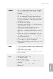
... and endurance. B150 Combo Chapter 1 Introduction hank you are using. Chapter 3 contains the operation guide of the BIOS setup. In this documentation will be subject to change without further notice. Chapter 4 contains the coniguration guide of the sotware and utilities. ASRock website http://www.asrock.com. 1.1 Package Contents • ASRock B150 Combo Motherboard (ATX Form Factor) • ASRock B150 Combo Quick Installation Guide • ASRock B150 Combo Support CD • 2 x Serial ATA (SATA) Data Cables (Optional) • 1 x I/O Panel Shield 1 English...
... and endurance. B150 Combo Chapter 1 Introduction hank you are using. Chapter 3 contains the operation guide of the BIOS setup. In this documentation will be subject to change without further notice. Chapter 4 contains the coniguration guide of the sotware and utilities. ASRock website http://www.asrock.com. 1.1 Package Contents • ASRock B150 Combo Motherboard (ATX Form Factor) • ASRock B150 Combo Quick Installation Guide • ASRock B150 Combo Support CD • 2 x Serial ATA (SATA) Data Cables (Optional) • 1 x I/O Panel Shield 1 English...
User Manual
Page 8
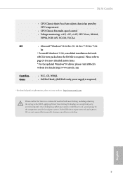
...) playback with DVI-D and HDMI Ports • 7.1 CH HD Audio with max. B150 Combo Graphics Audio LAN • Intel® HD Graphics Built-in Visuals and the VGA outputs can be supported only with processors which are GPU integrated. • Supports Intel® HD Graphics Built-in Visuals : Intel® Quick Sync Video with max. shared memory 1792MB • Dual graphics output: Support DVI-D and HDMI ports by independent display controllers • Supports HDMI with HEVC, AVC...
...) playback with DVI-D and HDMI Ports • 7.1 CH HD Audio with max. B150 Combo Graphics Audio LAN • Intel® HD Graphics Built-in Visuals and the VGA outputs can be supported only with processors which are GPU integrated. • Supports Intel® HD Graphics Built-in Visuals : Intel® Quick Sync Video with max. shared memory 1792MB • Dual graphics output: Support DVI-D and HDMI ports by independent display controllers • Supports HDMI with HEVC, AVC...

User Manual
Page 9
... USB 3.0 Header (Supports 2 USB 3.0 ports) (Supports ESD Protection (ASRock Full Spike Protection)) • 128Mb AMI UEFI Legal BIOS with LED (ACT/LINK LED and SPEED LED) • HD Audio Jacks: Side Speaker / Rear Speaker / Central / Bass / Line in / Front Speaker / Microphone • 6 x SATA3 6.0 Gb/s Connectors, support NCQ, AHCI and Hot Plug • 1 x COM Port Header • 1 x TPM Header • 1 x Power LED and Speaker Header • 2 x CPU Fan Connectors (4-pin) (Smart Fan Speed Control) • 3 x Chassis Fan Connectors (4-pin) (Smart Fan Speed Con- CPLL, VCCSA Voltage Multi...
... USB 3.0 Header (Supports 2 USB 3.0 ports) (Supports ESD Protection (ASRock Full Spike Protection)) • 128Mb AMI UEFI Legal BIOS with LED (ACT/LINK LED and SPEED LED) • HD Audio Jacks: Side Speaker / Rear Speaker / Central / Bass / Line in / Front Speaker / Microphone • 6 x SATA3 6.0 Gb/s Connectors, support NCQ, AHCI and Hot Plug • 1 x COM Port Header • 1 x TPM Header • 1 x Power LED and Speaker Header • 2 x CPU Fan Connectors (4-pin) (Smart Fan Speed Control) • 3 x Chassis Fan Connectors (4-pin) (Smart Fan Speed Con- CPLL, VCCSA Voltage Multi...
User Manual
Page 10
... detailed instructions. * For the updated Windows® 10 driver, please visit ASRock's website for possible damage caused by CPU temperature) • CPU/Chassis Fan multi-speed control • Voltage monitoring: +12V, +5V, +3.3V, CPU Vcore, DRAM, VPPM, PCH 1.0V, VCCIO, VCCSA • Microsot® Windows® 10 64-bit / 8.1 64-bit / 7 32-bit / 7 64bit * To install Windows® 7 OS, a modiied installation disk with overclocking, including adjusting the setting in the BIOS, applying Untied Overclocking Technology, or using third-party overclocking tools...
... detailed instructions. * For the updated Windows® 10 driver, please visit ASRock's website for possible damage caused by CPU temperature) • CPU/Chassis Fan multi-speed control • Voltage monitoring: +12V, +5V, +3.3V, CPU Vcore, DRAM, VPPM, PCH 1.0V, VCCIO, VCCSA • Microsot® Windows® 10 64-bit / 8.1 64-bit / 7 32-bit / 7 64bit * To install Windows® 7 OS, a modiied installation disk with overclocking, including adjusting the setting in the BIOS, applying Untied Overclocking Technology, or using third-party overclocking tools...

User Manual
Page 12
... 6 USB 3.0 Header (USB_5_6) 7 Chassis Fan Connector (CHA_FAN2) 8 SATA3 Connector (SATA3_0) 9 SATA3 Connector (SATA3_2) 10 SATA3 Connector (SATA3_1) 11 SATA3 Connector (SATA3_3) 12 SATA3 Connector (SATA3_5) 13 SATA3 Connector (SATA3_4) 14 System Panel Header (PANEL1) 15 Power LED and Speaker Header (SPK_PLED1) 16 USB 2.0 Header (USB_11_12) 17 USB 2.0 Header (USB_9_10) 18 Clear CMOS Jumper (CLRMOS1) 19 Chassis Fan Connector (CHA_FAN1) 20 TPM Header (TPMS1) 21 COM Port Header (COM1) 22 Front Panel Audio Header (HD_AUDIO1) 23 CPU Fan Connector (CPU_FAN1) 24 CPU Fan Connector (CPU_FAN2) B150 Combo...
... 6 USB 3.0 Header (USB_5_6) 7 Chassis Fan Connector (CHA_FAN2) 8 SATA3 Connector (SATA3_0) 9 SATA3 Connector (SATA3_2) 10 SATA3 Connector (SATA3_1) 11 SATA3 Connector (SATA3_3) 12 SATA3 Connector (SATA3_5) 13 SATA3 Connector (SATA3_4) 14 System Panel Header (PANEL1) 15 Power LED and Speaker Header (SPK_PLED1) 16 USB 2.0 Header (USB_11_12) 17 USB 2.0 Header (USB_9_10) 18 Clear CMOS Jumper (CLRMOS1) 19 Chassis Fan Connector (CHA_FAN1) 20 TPM Header (TPMS1) 21 COM Port Header (COM1) 22 Front Panel Audio Header (HD_AUDIO1) 23 CPU Fan Connector (CPU_FAN1) 24 CPU Fan Connector (CPU_FAN2) B150 Combo...

User Manual
Page 22
..., please connect a chassis fan to install expansion cards that the power supply is switched of the expansion card and make sure that have 32-bit PCI interface. B150 Combo 2.4 Expansion Slots (PCI and PCI Express Slots) here are used to the motherboard's chassis fan connector (CHA_FAN1, CHA_FAN2 or CHA_FAN3 when using multiple graphics cards. PCI slot: he PCI1 and PCI2 slots are 2 PCI slots and 4 PCI Express slots on the motherboard. PCIE3 (PCIe 3.0 x1 slot) is used for the card before you start the installation. PCIE4 (PCIe 3.0 x16 slot) is used for PCI Express x16...
..., please connect a chassis fan to install expansion cards that the power supply is switched of the expansion card and make sure that have 32-bit PCI interface. B150 Combo 2.4 Expansion Slots (PCI and PCI Express Slots) here are used to the motherboard's chassis fan connector (CHA_FAN1, CHA_FAN2 or CHA_FAN3 when using multiple graphics cards. PCI slot: he PCI1 and PCI2 slots are 2 PCI slots and 4 PCI Express slots on the motherboard. PCIE3 (PCIe 3.0 x1 slot) is used for the card before you start the installation. PCIE4 (PCIe 3.0 x16 slot) is used for PCI Express x16...

User Manual
Page 24
B150 Combo 2.6 Onboard Headers and Connectors Onboard headers and connectors are matched correctly. Note the positive and negative pins before connecting the cables. RESET (Reset Switch): Connect to the power switch on the chassis front panel. he LED is of when the system is in S1/S3 sleep state. Press the reset switch to restart the computer if the computer freezes and fails to the hard drive activity LED on when the system is on the chassis front...
B150 Combo 2.6 Onboard Headers and Connectors Onboard headers and connectors are matched correctly. Note the positive and negative pins before connecting the cables. RESET (Reset Switch): Connect to the power switch on the chassis front panel. he LED is of when the system is in S1/S3 sleep state. Press the reset switch to restart the computer if the computer freezes and fails to the hard drive activity LED on when the system is on the chassis front...

User Manual
Page 27
... securely store keys, digital certiicates, passwords, and data. A TPM system also helps enhance network security, protects digital identities, and ensures platform integrity. If you plan to Pin 1-3. vides an 8-pin ATX 12V 5 8 power connector. GN D English To use a 20-pin ATX power supply, please plug it along Pin 1 and Pin 5. his COM1 header supports a serial port module. To use a 4-pin ATX power supply, please plug it to connect a 3-Pin CPU fan, please connect it along Pin 1 and Pin 13. 1 4 his motherboard pro- ATX Power Connector (24-pin ATXPWR1) (see...
... securely store keys, digital certiicates, passwords, and data. A TPM system also helps enhance network security, protects digital identities, and ensures platform integrity. If you plan to Pin 1-3. vides an 8-pin ATX 12V 5 8 power connector. GN D English To use a 20-pin ATX power supply, please plug it along Pin 1 and Pin 5. his COM1 header supports a serial port module. To use a 4-pin ATX power supply, please plug it to connect a 3-Pin CPU fan, please connect it along Pin 1 and Pin 13. 1 4 his motherboard pro- ATX Power Connector (24-pin ATXPWR1) (see...
User Manual
Page 28
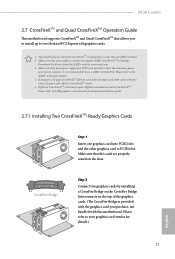
... card with this motherboard. CrossFire Bridge Step 2 Connect two graphics cards by installing a CrossFire Bridge on the CrossFire Bridge Interconnects on the slots. Download the drivers from the AMD's website: www.amd.com 3. If you purchase, not bundled with a 16-pipe card, both cards will operate as 12-pipe cards while in CrossFireXTM mode. 5. You should only use a AMD certiied PSU. B150 Combo 2.7 CrossFireXTM and Quad CrossFireXTM Operation Guide his motherboard supports...
... card with this motherboard. CrossFire Bridge Step 2 Connect two graphics cards by installing a CrossFire Bridge on the CrossFire Bridge Interconnects on the slots. Download the drivers from the AMD's website: www.amd.com 3. If you purchase, not bundled with a 16-pipe card, both cards will operate as 12-pipe cards while in CrossFireXTM mode. 5. You should only use a AMD certiied PSU. B150 Combo 2.7 CrossFireXTM and Quad CrossFireXTM Operation Guide his motherboard supports...
User Manual
Page 30
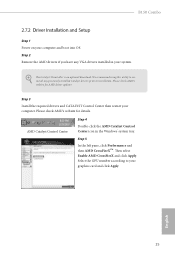
... optional download. Step 5 In the let pane, click Performance and then AMD CrossFireXTM. B150 Combo 2.7.2 Driver Installation and Setup Step 1 Power on your computer. Please check AMD's website for details. We recommend using this utility to uninstall any VGA drivers installed in the Windows® system tray. Step 3 Install the required drivers and CATALYST Control Center then restart your computer and boot into OS. Select the GPU number according to installation. AMD...
... optional download. Step 5 In the let pane, click Performance and then AMD CrossFireXTM. B150 Combo 2.7.2 Driver Installation and Setup Step 1 Power on your computer. Please check AMD's website for details. We recommend using this utility to uninstall any VGA drivers installed in the Windows® system tray. Step 3 Install the required drivers and CATALYST Control Center then restart your computer and boot into OS. Select the GPU number according to installation. AMD...

User Manual
Page 31
... useful utilities that the motherboard supports. herefore, the drivers you install can work properly. To improve Windows 7 compatibility, please download and install the following hot ix provided by Microsot. he CD automatically displays the Main Menu if "AUTORUN" is enabled in the Support CD to install those required drivers. Click on the ile "ASRSETUP.EXE" in your computer. Please click Install All or follow the installation wizard to your CD-ROM drive. Drivers Menu...
... useful utilities that the motherboard supports. herefore, the drivers you install can work properly. To improve Windows 7 compatibility, please download and install the following hot ix provided by Microsot. he CD automatically displays the Main Menu if "AUTORUN" is enabled in the Support CD to install those required drivers. Click on the ile "ASRSETUP.EXE" in your computer. Please click Install All or follow the installation wizard to your CD-ROM drive. Drivers Menu...
User Manual
Page 38
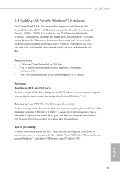
... included in the ASRock Support CD or website) Scenarios You have an optical disc drive, please ind another computer and follow the instructions below and go ahead to function properly, please create a Windows® 7 installation disk with the "Win7 USB Patcher". In order for the USB ports to install Windows® 7 OS. B150 Combo 3.4 Enabling USB Ports for Windows® 7 Installation Intel® Braswell and Skylake has removed their motherboard won't work.
... included in the ASRock Support CD or website) Scenarios You have an optical disc drive, please ind another computer and follow the instructions below and go ahead to function properly, please create a Windows® 7 installation disk with the "Win7 USB Patcher". In order for the USB ports to install Windows® 7 OS. B150 Combo 3.4 Enabling USB Ports for Windows® 7 Installation Intel® Braswell and Skylake has removed their motherboard won't work.

User Manual
Page 39
Step 4 Select the "USB Driver Folder" by clicking the red circle as shown as the picture below . Instructions Step 1 Insert the Windows® 7 installation disk or USB drive to your CD-ROM. 34 English If you are using ASRock's Support CD for the USB 3.0 driver, please select your system. Step 3 Select the "Win7 Folder" from Step1 by clicking the red circle as shown as the picture below . Step 2 Extract the tool (Win7 USB Patcher) and launch it.
Step 4 Select the "USB Driver Folder" by clicking the red circle as shown as the picture below . Instructions Step 1 Insert the Windows® 7 installation disk or USB drive to your CD-ROM. 34 English If you are using ASRock's Support CD for the USB 3.0 driver, please select your system. Step 3 Select the "Win7 Folder" from Step1 by clicking the red circle as shown as the picture below . Step 2 Extract the tool (Win7 USB Patcher) and launch it.

User Manual
Page 55
... I/O helps your virtual machine monitor better utilize hardware by improving application compatibility and reliability, and providing additional levels of manageability, security, isolation, and I/O performance. PCIE4 Link Speed Select the link speed for all CPU downstream devices. 50 English PCIE ASPM Support his option enables/disables the ASPM support for PCIE4. 4.4.2 Chipset Coniguration Primary Graphics Adapter Select a primary VGA. Top of Lower Usable DRAM Set the maximum value of the installed graphic controller.
... I/O helps your virtual machine monitor better utilize hardware by improving application compatibility and reliability, and providing additional levels of manageability, security, isolation, and I/O performance. PCIE4 Link Speed Select the link speed for all CPU downstream devices. 50 English PCIE ASPM Support his option enables/disables the ASPM support for PCIE4. 4.4.2 Chipset Coniguration Primary Graphics Adapter Select a primary VGA. Top of Lower Usable DRAM Set the maximum value of the installed graphic controller.

User Manual
Page 56
... a power failure. Front Panel Enable/disable front panel HD audio. DMI ASPM Support his option enables/disables the ASPM support for all times. If [Power Of] is installed. Onboard HD Audio Enable/disable onboard HD audio. Restore on CPU side of when the power recovers. IGPU Multi-Monitor Select disable to enable onboard HD audio and automatically disable it when a sound card is selected, the power will start to boot up . If [Power On] is allocated to keep the integrated graphics enabled at all PCH PCIE devices. Share Memory...
... a power failure. Front Panel Enable/disable front panel HD audio. DMI ASPM Support his option enables/disables the ASPM support for all times. If [Power Of] is installed. Onboard HD Audio Enable/disable onboard HD audio. Restore on CPU side of when the power recovers. IGPU Multi-Monitor Select disable to enable onboard HD audio and automatically disable it when a sound card is selected, the power will start to boot up . If [Power On] is allocated to keep the integrated graphics enabled at all PCH PCIE devices. Share Memory...

User Manual
Page 59
PS2 Y-Cable Enable the PS2 Y-Cable or set this option to Auto. 54 English Serial Port Address Select the address of the Serial port. 4.4.4 Super IO Coniguration Serial Port Enable or disable the Serial port.
PS2 Y-Cable Enable the PS2 Y-Cable or set this option to Auto. 54 English Serial Port Address Select the address of the Serial port. 4.4.4 Super IO Coniguration Serial Port Enable or disable the Serial port.
User Manual
Page 63
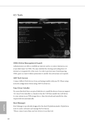
... manage the boot menu. *Please connect more than one boot devices to modify the system time are having trouble with your system via OMG. Please setup network coniguration before using UEFI Tech Service. 4.5 Tools OMG (Online Management Guard) Administrators are able to establish an internet curfew or restrict internet access at speciied times via an USB storage device, then downloads and installs the other users. Easy Driver Installer For users that...
... manage the boot menu. *Please connect more than one boot devices to modify the system time are having trouble with your system via OMG. Please setup network coniguration before using UEFI Tech Service. 4.5 Tools OMG (Online Management Guard) Administrators are able to establish an internet curfew or restrict internet access at speciied times via an USB storage device, then downloads and installs the other users. Easy Driver Installer For users that...

User Manual
Page 65
... drive before using this to plug in your UEFI. Please setup network coniguration before using Internet Flash. *For BIOS backup and recovery purpose, it is enabled. Network Coniguration Use this function. DHCP (Auto IP), Auto ASRock Internet Flash downloads and updates the latest UEFI irmware version from our servers for Internet Flash. Dehumidiier CPU Fan Setting Conigure the speed of the CPU fan while Dehumidiier is recommended to conigure internet connection settings for you. Internet Flash - Internet Setting Enable or disable sound efects in the setup utility...
... drive before using this to plug in your UEFI. Please setup network coniguration before using Internet Flash. *For BIOS backup and recovery purpose, it is enabled. Network Coniguration Use this function. DHCP (Auto IP), Auto ASRock Internet Flash downloads and updates the latest UEFI irmware version from our servers for Internet Flash. Dehumidiier CPU Fan Setting Conigure the speed of the CPU fan while Dehumidiier is recommended to conigure internet connection settings for you. Internet Flash - Internet Setting Enable or disable sound efects in the setup utility...

User Manual
Page 68
... to remove the password. Disable this option to change the settings in the UEFI Setup Utility. Supervisor Password Set or change the password for Windows 8.1 Secure Boot. Leave it blank and press enter to change the settings in ME. Leave it blank and press enter to enable or disable support for the administrator account. Secure Boot Use this item to remove the password. Only the administrator has authority to use discrete TPM Module. 63 English B150 Combo 4.7 Security Screen In...
... to remove the password. Disable this option to change the settings in the UEFI Setup Utility. Supervisor Password Set or change the password for Windows 8.1 Secure Boot. Leave it blank and press enter to change the settings in ME. Leave it blank and press enter to enable or disable support for the administrator account. Secure Boot Use this item to remove the password. Only the administrator has authority to use discrete TPM Module. 63 English B150 Combo 4.7 Security Screen In...


