
User Manual
Page 4
... 54 3.1 Introduction 54 3.1.1 BIOS Menu Bar 54 3.1.2 Navigation Keys 55 3.2 Main Screen 55 3.3 Smart Screen 56 3.4 Advanced Screen 57 3.4.1 CPU Configuration 57 3.4.2 Chipset Configuration 62 3.4.3 ACPI Configuration 64 3.4.4 IDE ...
... 54 3.1 Introduction 54 3.1.1 BIOS Menu Bar 54 3.1.2 Navigation Keys 55 3.2 Main Screen 55 3.3 Smart Screen 56 3.4 Advanced Screen 57 3.4.1 CPU Configuration 57 3.4.2 Chipset Configuration 62 3.4.3 ACPI Configuration 64 3.4.4 IDE ...
User Manual
Page 5
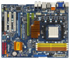
...) Data Cables (Optional) 1 x Serial ATA (SATA) HDD Power Cable (Optional) 1 x ASRock SLI/XFire Switch Card 1 x DVI-to BIOS setup and information of this motherboard, please visit our website for specific information about the model you for purchasing ASRock AOD790GX/128M motherboard, a reliable motherboard produced under ASRock's consistently stringent quality control. It delivers excellent performance with robust...
...) Data Cables (Optional) 1 x Serial ATA (SATA) HDD Power Cable (Optional) 1 x ASRock SLI/XFire Switch Card 1 x DVI-to BIOS setup and information of this motherboard, please visit our website for specific information about the model you for purchasing ASRock AOD790GX/128M motherboard, a reliable motherboard produced under ASRock's consistently stringent quality control. It delivers excellent performance with robust...

User Manual
Page 7
... "Plug and Play" - CPU, DRAM, NB Voltage Multi-adjustment - Realtek RTL8111C-VCO-GR - Supports Wake-On-LAN I /O Connector BIOS Feature - SLI/XFIRE power connector - SMBIOS 2.3.1 Support - Supports Smart BIOS 7 Front panel audio connector - 2 x USB 2.0 headers (support 4 USB 2.0 ports) (see CAUTION 12) - 1 x USB/WiFi header (see CAUTION 11) - 1 x ATA133 IDE... - 1 x VGA/DVI-D Port - 6 x Ready-to-Use USB 2.0 Ports - 1 x eSATAII Port - 1 x RJ-45 LAN Port with 1 SATAII connector) (see CAUTION 13) - 8Mb AMI BIOS - Supports jumperfree - PCIE x1 Gigabit LAN 10/100/1000 Mb/s -
... "Plug and Play" - CPU, DRAM, NB Voltage Multi-adjustment - Realtek RTL8111C-VCO-GR - Supports Wake-On-LAN I /O Connector BIOS Feature - SLI/XFIRE power connector - SMBIOS 2.3.1 Support - Supports Smart BIOS 7 Front panel audio connector - 2 x USB 2.0 headers (support 4 USB 2.0 ports) (see CAUTION 12) - 1 x USB/WiFi header (see CAUTION 11) - 1 x ATA133 IDE... - 1 x VGA/DVI-D Port - 6 x Ready-to-Use USB 2.0 Ports - 1 x eSATAII Port - 1 x RJ-45 LAN Port with 1 SATAII connector) (see CAUTION 13) - 8Mb AMI BIOS - Supports jumperfree - PCIE x1 Gigabit LAN 10/100/1000 Mb/s -
User Manual
Page 8
...-bit and Windows® VistaTM 64bit with 64-bit CPU, there is a certain risk involved with overclocking, including adjusting the setting in the BIOS, applying Untied Overclocking Technology, or using the thirdparty overclocking tools. We are not responsible for details. 2. Voltage Monitoring: +12V, +5V, ... affect your system stability, or even cause damage to 12.5% (see CAUTION 14) - CPU Temperature Sensing Monitor - ASRock OC Tuner (see CAUTION 18) Hardware - ASRock U-COP (see CAUTION 15) - Whether 1066MHz memory speed is supported depends on the AM2+ CPU you implement Dual ...
...-bit and Windows® VistaTM 64bit with 64-bit CPU, there is a certain risk involved with overclocking, including adjusting the setting in the BIOS, applying Untied Overclocking Technology, or using the thirdparty overclocking tools. We are not responsible for details. 2. Voltage Monitoring: +12V, +5V, ... affect your system stability, or even cause damage to 12.5% (see CAUTION 14) - CPU Temperature Sensing Monitor - ASRock OC Tuner (see CAUTION 18) Hardware - ASRock U-COP (see CAUTION 15) - Whether 1066MHz memory speed is supported depends on the AM2+ CPU you implement Dual ...

User Manual
Page 9
...: http://www.asrock.com 15. In other words, it is subject to -use Intelligent Energy Saver function, please enable Cool 'n' Quiet option in the BIOS setup in our lab test. 9. Please check AMD website for the availability of wireless network connectivity. Before installing SATAII hard disk to support 2 USB 2.0 ports. 5. ...
...: http://www.asrock.com 15. In other words, it is subject to -use Intelligent Energy Saver function, please enable Cool 'n' Quiet option in the BIOS setup in our lab test. 9. Please check AMD website for the availability of wireless network connectivity. Before installing SATAII hard disk to support 2 USB 2.0 ports. 5. ...

User Manual
Page 10
...18. You may cause the instability of your system. Although this function will overclock the chipset/CPU reference clock. This motherboard supports ASRock AM2 Boost overclocking technology. However, we can not guarantee the system stability for keeping the stability of the system or damage the... CPU. 17. Frequencies other than the recommended CPU bus frequencies may choose to disable this function in the BIOS setup, the memory performance will automatically shutdown. Enabling this motherboard offers stepless control, it is detected, the system will improve ...
...18. You may cause the instability of your system. Although this function will overclock the chipset/CPU reference clock. This motherboard supports ASRock AM2 Boost overclocking technology. However, we can not guarantee the system stability for keeping the stability of the system or damage the... CPU. 17. Frequencies other than the recommended CPU bus frequencies may choose to disable this function in the BIOS setup, the memory performance will automatically shutdown. Enabling this motherboard offers stepless control, it is detected, the system will improve ...
User Manual
Page 13
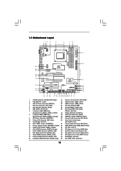
...: FRONT Bottom: MIC IN PCIE1 LAN PHY 1394a AMD 790GX Chipset PCIE2 PCI Express 2.0 Super I/O AUDIO CODEC USB/WIFI HDMI_SPDIF1 1 HD_AUDIO1 1 CD1 PCIE3 AOD790GX/128M PCI1 PCI2 RoHS RAID 8Mb BIOS AMD SB750 Chipset PCI3 1 COM1 FLOPPY1 FRONT_1394 1 IR1 1 USB6_7 1 USB8_9 1 SATAII_2 SATAII_4 CHA_FAN1 SATAII_1 SATAII_3 CMOS BATTERY CLRCMOS1 1 SPEAKER1 1 PANEL 1 PLED PWRBTN...
...: FRONT Bottom: MIC IN PCIE1 LAN PHY 1394a AMD 790GX Chipset PCIE2 PCI Express 2.0 Super I/O AUDIO CODEC USB/WIFI HDMI_SPDIF1 1 HD_AUDIO1 1 CD1 PCIE3 AOD790GX/128M PCI1 PCI2 RoHS RAID 8Mb BIOS AMD SB750 Chipset PCI3 1 COM1 FLOPPY1 FRONT_1394 1 IR1 1 USB6_7 1 USB8_9 1 SATAII_2 SATAII_4 CHA_FAN1 SATAII_1 SATAII_3 CMOS BATTERY CLRCMOS1 1 SPEAKER1 1 PANEL 1 PLED PWRBTN...

User Manual
Page 27
... PCI Express graphics card support list for both the onboard VGA and the discrete graphics card. For the proper installation procedures, please refer to enter BIOS setup. Please refer to a single display for further information. Boot your computer. Enter "Advanced" screen, and enter "Chipset Settings". Step 4. Step 5. Restart your system. In...
... PCI Express graphics card support list for both the onboard VGA and the discrete graphics card. For the proper installation procedures, please refer to enter BIOS setup. Please refer to a single display for further information. Boot your computer. Enter "Advanced" screen, and enter "Chipset Settings". Step 4. Step 5. Restart your system. In...

User Manual
Page 30
... the external add-on PCI Express VGA card driver to install them again. 6. Please refer to enter BIOS setup. If you connect the DVI-to-HDMI converter to the VGA/DVI-D port, please connect the HDMI...Auto], will run at x16 bandwidth. 1. Set up a surround display environment: If you do not adjust the BIOS setup, the default value of both monitors. And connect the D-Sub monitor cable to this motherboard. Therefore, the... on PCIE3 slot. If you can freely enjoy the benefits of ASRock SLI/XFire Switch Card to switch it to enable the function of the system memory. Boot your ...
... the external add-on PCI Express VGA card driver to install them again. 6. Please refer to enter BIOS setup. If you connect the DVI-to-HDMI converter to the VGA/DVI-D port, please connect the HDMI...Auto], will run at x16 bandwidth. 1. Set up a surround display environment: If you do not adjust the BIOS setup, the default value of both monitors. And connect the D-Sub monitor cable to this motherboard. Therefore, the... on PCIE3 slot. If you can freely enjoy the benefits of ASRock SLI/XFire Switch Card to switch it to enable the function of the system memory. Boot your ...

User Manual
Page 33
... short pin2 and pin3 on these 2 pins. To clear and reset the system parameters to clear the CMOS when you just finish updating the BIOS, you update the BIOS. Note: To select +5VSB, it down before you do not clear the CMOS right after you must boot up events. If no jumper...
... short pin2 and pin3 on these 2 pins. To clear and reset the system parameters to clear the CMOS when you just finish updating the BIOS, you update the BIOS. Note: To select +5VSB, it down before you do not clear the CMOS right after you must boot up events. If no jumper...

User Manual
Page 36
... front panel jack detection", and save the change by clicking "OK". G. Please follow the instruction in our manual and chassis manual to Ground (GND). D. Enter BIOS Setup Utility. Enter Windows system. C. Connect Ground (GND) to install your system. 2. Enter Advanced Settings, and then select Chipset Configuration. For Windows® XP / XP...
... front panel jack detection", and save the change by clicking "OK". G. Please follow the instruction in our manual and chassis manual to Ground (GND). D. Enter BIOS Setup Utility. Enter Windows system. C. Connect Ground (GND) to install your system. 2. Enter Advanced Settings, and then select Chipset Configuration. For Windows® XP / XP...

User Manual
Page 41
.... 2. eSATAII allows you still want to add the eSATAII HDD as a removable data disk, please set "SATA Operation Mode" option in BIOS setup to exchange drives easily. If you can insert or remove your eSATAII devices to the eSATAII ports while the system is eSATAII? eSATAII ...is power-off. 3. For example, with eSATAII devices. If you set "SATA Operation Mode" option in BIOS setup to RAID mode. Currently, on the market, the data transfer rate of Hot Plug feature. This motherboard supports eSATAII interface, the external SATAII...
.... 2. eSATAII allows you still want to add the eSATAII HDD as a removable data disk, please set "SATA Operation Mode" option in BIOS setup to exchange drives easily. If you can insert or remove your eSATAII devices to the eSATAII ports while the system is eSATAII? eSATAII ...is power-off. 3. For example, with eSATAII devices. If you set "SATA Operation Mode" option in BIOS setup to RAID mode. Currently, on the market, the data transfer rate of Hot Plug feature. This motherboard supports eSATAII interface, the external SATAII...

User Manual
Page 49
... UTILITY Advanced screen IDE Configuration. Please select CD-ROM as the boot device. Then you need to the BIOS RAID installation guide part of 2 or more SATA / SATAII HDDs with RAID functions, please follow below procedures according to the OS you install. 2.17.1 Installing ...® XP 64-bit, Windows® VistaTM or Windows® VistaTM 64-bit on the support CD driver page. C. Please follow below steps. Insert the ASRock Support CD into floppy drive A: press any key. D. 2.16 Driver Installation Guide To install the drivers to your system, please insert the support CD to...
... UTILITY Advanced screen IDE Configuration. Please select CD-ROM as the boot device. Then you need to the BIOS RAID installation guide part of 2 or more SATA / SATAII HDDs with RAID functions, please follow below procedures according to the OS you install. 2.17.1 Installing ...® XP 64-bit, Windows® VistaTM or Windows® VistaTM 64-bit on the support CD driver page. C. Please follow below steps. Insert the ASRock Support CD into floppy drive A: press any key. D. 2.16 Driver Installation Guide To install the drivers to your system, please insert the support CD to...

User Manual
Page 50
... drive to boot your system, and follow below steps. STEP 1: Set up "SATA Operation Mode" to [RAID] first. " page, please insert the ASRock Support CD into your system. After reading the floppy disk, the driver will be presented. B. Then, please set RAID configuration. STEP 2: Use "RAID... continue the installation. 50 Insert the Windows® VistaTM / Windows® VistaTM 64-bit optical disk into the optical drive again to the BIOS RAID installation guide part of 2 or more SATA / SATAII HDDs with RAID functions, please follow the instruction to install Windows® VistaTM /...
... drive to boot your system, and follow below steps. STEP 1: Set up "SATA Operation Mode" to [RAID] first. " page, please insert the ASRock Support CD into your system. After reading the floppy disk, the driver will be presented. B. Then, please set RAID configuration. STEP 2: Use "RAID... continue the installation. 50 Insert the Windows® VistaTM / Windows® VistaTM 64-bit optical disk into the optical drive again to the BIOS RAID installation guide part of 2 or more SATA / SATAII HDDs with RAID functions, please follow the instruction to install Windows® VistaTM /...

User Manual
Page 51
... need to set up "SATA Operation Mode" to [RAID] in SATA AHCI ROM, the SATA ID description will be presented. Enter BIOS SETUP UTILITY Advanced screen IDE Configuration. After step 1, 2, 3, you install. Select the driver to install according to the OS you install...XP 64-bit OS on your system. When prompted, insert the SATA / SATAII driver diskette containing the AMD AHCI driver. A. B. Please notice in BIOS first. NOTE. After reading the floppy disk, the driver will start to [non-RAID] in the Support CD: .. \ RAID Installation Guide NOTE2....
... need to set up "SATA Operation Mode" to [RAID] in SATA AHCI ROM, the SATA ID description will be presented. Enter BIOS SETUP UTILITY Advanced screen IDE Configuration. After step 1, 2, 3, you install. Select the driver to install according to the OS you install...XP 64-bit OS on your system. When prompted, insert the SATA / SATAII driver diskette containing the AMD AHCI driver. A. B. Please notice in BIOS first. NOTE. After reading the floppy disk, the driver will start to [non-RAID] in the Support CD: .. \ RAID Installation Guide NOTE2....

User Manual
Page 52
...2: Install Windows® VistaTM / VistaTM 64-bit OS on your system. Enter BIOS SETUP UTILITY Advanced screen IDE Configuration. Set the "SATA Operation Mode" option to load the AMD AHCI drivers. B. page, please insert the ASRock Support CD into your optical drive, and click the "Load Driver" button on ... SATA / SATAII HDDs and eSATAII devices with NCQ and Hot Plug functions STEP 1: Set Up BIOS. AMD AHCI drivers are in the following path in our Support CD: (There are two ASRock Support CD in the motherboard gift box pack, please choose the one for Windows® XP 64...
...2: Install Windows® VistaTM / VistaTM 64-bit OS on your system. Enter BIOS SETUP UTILITY Advanced screen IDE Configuration. Set the "SATA Operation Mode" option to load the AMD AHCI drivers. B. page, please insert the ASRock Support CD into your optical drive, and click the "Load Driver" button on ... SATA / SATAII HDDs and eSATAII devices with NCQ and Hot Plug functions STEP 1: Set Up BIOS. AMD AHCI drivers are in the following path in our Support CD: (There are two ASRock Support CD in the motherboard gift box pack, please choose the one for Windows® XP 64...

User Manual
Page 53
... better margin due to the warning on page 8 for the possible overclocking risk before you enable Untied Overclocking function, please enter "Overclock Mode" option of BIOS setup to set the selection from [Auto] to [CPU, PCIE, Async.].
... better margin due to the warning on page 8 for the possible overclocking risk before you enable Untied Overclocking function, please enter "Overclock Mode" option of BIOS setup to set the selection from [Auto] to [CPU, PCIE, Async.].

User Manual
Page 54
...pressing + + , or by turning the system off and then back on the menu bar, and then press to choose among the selections on . Because the BIOS software is constantly being updated, the following selections: Main To set up the system time/date information Advanced To set up the advanced... current hardware status Boot To set up the default system device to configure your screen. 3.1.1 BIOS Menu Bar The top of the screen has a menu bar with its test routines. You may run the BIOS SETUP UTILITY when you see on your system. You may also restart by pressing the reset...
...pressing + + , or by turning the system off and then back on the menu bar, and then press to choose among the selections on . Because the BIOS software is constantly being updated, the following selections: Main To set up the system time/date information Advanced To set up the advanced... current hardware status Boot To set up the default system device to configure your screen. 3.1.1 BIOS Menu Bar The top of the screen has a menu bar with its test routines. You may run the BIOS SETUP UTILITY when you see on your system. You may also restart by pressing the reset...

User Manual
Page 55
... UTILITY Main Smart Advanced H/W Monitor Boot Security Exit System Overview System Time System Date [17:00:09] [Mon 07/04/2008] BIOS Version : AOD790GX/128M P1.0 Processor Type : AMD Athlon(tm) 64 X2 Dual Core Processor 4800+ (64bit) Processor Speed : 2400MHz Microcode Update : 40F32/62 L1 Cache Size :...] to specify the system date. 55 3.1.2 Navigation Keys Please check the following table for all the settings To save changes and exit the BIOS SETUP UTILITY To jump to configure system Time. +Tab F1 F9 F10 ESC Select Screen Select Item Change Field Select Field General Help Load ...
... UTILITY Main Smart Advanced H/W Monitor Boot Security Exit System Overview System Time System Date [17:00:09] [Mon 07/04/2008] BIOS Version : AOD790GX/128M P1.0 Processor Type : AMD Athlon(tm) 64 X2 Dual Core Processor 4800+ (64bit) Processor Speed : 2400MHz Microcode Update : 40F32/62 L1 Cache Size :...] to specify the system date. 55 3.1.2 Navigation Keys Please check the following table for all the settings To save changes and exit the BIOS SETUP UTILITY To jump to configure system Time. +Tab F1 F9 F10 ESC Select Screen Select Item Change Field Select Field General Help Load ...

User Manual
Page 56
... this operation. F4 key can be compatible with all system configurations. F5 key can be used for all system configurations. Load BIOS Defaults Load BIOS default values for this operation. 56 F6 key can be used for this operation. If system boot failure occurs after saving the... changes. F10 key can load the BIOS setup according to your requirements. Load Performance Setup RAID Mode This performance setup RAID mode may not be compatible with all the setup ...
... this operation. F4 key can be compatible with all system configurations. F5 key can be used for all system configurations. Load BIOS Defaults Load BIOS default values for this operation. 56 F6 key can be used for this operation. If system boot failure occurs after saving the... changes. F10 key can load the BIOS setup according to your requirements. Load Performance Setup RAID Mode This performance setup RAID mode may not be compatible with all the setup ...


