
User Manual
Page 6
Supports AMD's Cool 'n' QuietTM Technology - shared memory 256MB (see CAUTION 2) - 4 x DDR2 DIMM slots - Chipset embedded HDMI Audio - 1.2 Specifications Platform CPU Chipset Memory Expansion Slot Graphics Audio LAN Rear Panel I /O - 1 x PS/2 Mouse Port - 1 x PS/2 Keyboard Port - 1 x VGA/D-Sub Port 6 AMD... (ALC662 Audio Codec) - Max. Support for AM3 processors: AMD PhenomTM II X4 / X3 and Athlon II X4 / X3 / X2 processors - Support for Socket AM2+ / AM2 processors: AMD PhenomTM FX / Phenom / Athlon 64 FX / Athlon 64 X2 Dual-Core / Athlon X2 Dual-Core / Athlon 64 / ...
Supports AMD's Cool 'n' QuietTM Technology - shared memory 256MB (see CAUTION 2) - 4 x DDR2 DIMM slots - Chipset embedded HDMI Audio - 1.2 Specifications Platform CPU Chipset Memory Expansion Slot Graphics Audio LAN Rear Panel I /O - 1 x PS/2 Mouse Port - 1 x PS/2 Keyboard Port - 1 x VGA/D-Sub Port 6 AMD... (ALC662 Audio Codec) - Max. Support for AM3 processors: AMD PhenomTM II X4 / X3 and Athlon II X4 / X3 / X2 processors - Support for Socket AM2+ / AM2 processors: AMD PhenomTM FX / Phenom / Athlon 64 FX / Athlon 64 X2 Dual-Core / Athlon X2 Dual-Core / Athlon 64 / ...

User Manual
Page 12
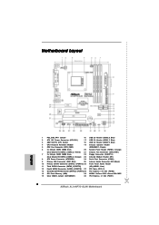
...W R 1 24.4cm (9.6-in) PARALLEL PORT SOCKET AM2 VGA1 30 29 28 27 Top: Line In Center: Line Out Bottom: Mic In USB 2.0 T: USB2 B: USB3 USB 2.0 T: USB0 B: USB1 Top: RJ-45 LAN PHY Phenom II DDR2 1066 ALiveNF7G-GLAN Dual Channel PCIE1 NVIDIA GeForce 7050 / nForce 630A... (USB8_9, Blue) 2 ATX 12V Power Connector (ATX12V1) 17 USB 2.0 Header (USB6_7, Blue) 3 AM2 940-Pin CPU Socket 18 USB 2.0 Header (USB4_5, Blue) 4 CPU Heatsink Retention Module 19 Chassis Speaker Header 5 CPU Fan Connector (CPU_FAN1) (SPEAKER 1, Purple) 6 2 x 240-pin DDR2 DIMM Slots 20 System Panel Header (PANEL1, ...
...W R 1 24.4cm (9.6-in) PARALLEL PORT SOCKET AM2 VGA1 30 29 28 27 Top: Line In Center: Line Out Bottom: Mic In USB 2.0 T: USB2 B: USB3 USB 2.0 T: USB0 B: USB1 Top: RJ-45 LAN PHY Phenom II DDR2 1066 ALiveNF7G-GLAN Dual Channel PCIE1 NVIDIA GeForce 7050 / nForce 630A... (USB8_9, Blue) 2 ATX 12V Power Connector (ATX12V1) 17 USB 2.0 Header (USB6_7, Blue) 3 AM2 940-Pin CPU Socket 18 USB 2.0 Header (USB4_5, Blue) 4 CPU Heatsink Retention Module 19 Chassis Speaker Header 5 CPU Fan Connector (CPU_FAN1) (SPEAKER 1, Purple) 6 2 x 240-pin DDR2 DIMM Slots 20 System Panel Header (PANEL1, ...

User Manual
Page 15
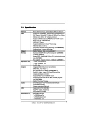
...in good contact with a small triangle. Then connect the CPU fan to secure the CPU. DO NOT force the CPU into the socket to indicate that it is locked. The lever clicks on the socket while you install the CPU into the socket until it firmly on the side tab to avoid bending ... Heatsink After you push down the socket lever to the CPU FAN connector (CPU_FAN1, see Page 12, No. 5). Make sure that the CPU corner with the golden triangle matches the socket corner with each other. Position the CPU directly above the socket such that the CPU and the heatsink are securely fastened ...
...in good contact with a small triangle. Then connect the CPU fan to secure the CPU. DO NOT force the CPU into the socket to indicate that it is locked. The lever clicks on the socket while you install the CPU into the socket until it firmly on the side tab to avoid bending ... Heatsink After you push down the socket lever to the CPU FAN connector (CPU_FAN1, see Page 12, No. 5). Make sure that the CPU corner with the golden triangle matches the socket corner with each other. Position the CPU directly above the socket such that the CPU and the heatsink are securely fastened ...
Quick Installation Guide
Page 2
... (CLRCMOS1) 30 PCI Express x1 Slot (PCIE1) 2 ASRock ALiveNF7G-GLAN Motherboard Motherboard Layout English 1 PS2_USB_PW1 Jumper 16 USB 2.0 Header (USB8_9, Blue) 2 ATX 12V Power Connector (ATX12V1) 17 USB 2.0 Header (USB6_7, Blue) 3 AM2 940-Pin CPU Socket 18 USB 2.0 Header (USB4_5, Blue) 4 CPU Heatsink Retention Module 19 Chassis Speaker Header 5 CPU Fan Connector (CPU_FAN1) (SPEAKER 1, Purple) 6 2 x 240-pin...
... (CLRCMOS1) 30 PCI Express x1 Slot (PCIE1) 2 ASRock ALiveNF7G-GLAN Motherboard Motherboard Layout English 1 PS2_USB_PW1 Jumper 16 USB 2.0 Header (USB8_9, Blue) 2 ATX 12V Power Connector (ATX12V1) 17 USB 2.0 Header (USB6_7, Blue) 3 AM2 940-Pin CPU Socket 18 USB 2.0 Header (USB4_5, Blue) 4 CPU Heatsink Retention Module 19 Chassis Speaker Header 5 CPU Fan Connector (CPU_FAN1) (SPEAKER 1, Purple) 6 2 x 240-pin...
Quick Installation Guide
Page 5
...X2 processors - Supports Untied Overclocking Technology (see CAUTION 5) - shared memory 256MB (see CAUTION 1) - Chipset embedded HDMI Audio - Support for Socket AM2+ / AM2 processors: AMD PhenomTM FX / Phenom / Athlon 64 FX / Athlon 64 X2 Dual-Core / Athlon X2 Dual-Core ... 3.0 - Gigabit LAN 10/100/1000 Mb/s - 1.2 Specifications Platform CPU Chipset Memory Expansion Slot Graphics Audio LAN Rear Panel I /O - 1 x PS/2 Mouse Port - 1 x PS/2 Keyboard Port - 1 x VGA/D-Sub Port 5 ASRock ALiveNF7G-GLAN Motherboard English NVIDIA® PureVideoTM Ready - 5.1 CH Windows® VistaTM...
...X2 processors - Supports Untied Overclocking Technology (see CAUTION 5) - shared memory 256MB (see CAUTION 1) - Chipset embedded HDMI Audio - Support for Socket AM2+ / AM2 processors: AMD PhenomTM FX / Phenom / Athlon 64 FX / Athlon 64 X2 Dual-Core / Athlon X2 Dual-Core ... 3.0 - Gigabit LAN 10/100/1000 Mb/s - 1.2 Specifications Platform CPU Chipset Memory Expansion Slot Graphics Audio LAN Rear Panel I /O - 1 x PS/2 Mouse Port - 1 x PS/2 Keyboard Port - 1 x VGA/D-Sub Port 5 ASRock ALiveNF7G-GLAN Motherboard English NVIDIA® PureVideoTM Ready - 5.1 CH Windows® VistaTM...
Quick Installation Guide
Page 11
.... The lever clicks on the carpet or the like. Step 5. Install CPU fan and heatsink. Whenever you push down the socket lever to static electricity, NEVER place your CPU fan and heatsink vendors. Step 4. For proper installation, please kindly refer ... English 11 ASRock ALiveNF7G-GLAN Motherboard Unplug the power cord from the wall socket before you handle components. 3. Step 2. The CPU fits only in the bag that the CPU corner with the golden triangle matches the socket corner with the component. 5. Position the CPU directly above the socket such that ...
.... The lever clicks on the carpet or the like. Step 5. Install CPU fan and heatsink. Whenever you push down the socket lever to static electricity, NEVER place your CPU fan and heatsink vendors. Step 4. For proper installation, please kindly refer ... English 11 ASRock ALiveNF7G-GLAN Motherboard Unplug the power cord from the wall socket before you handle components. 3. Step 2. The CPU fits only in the bag that the CPU corner with the golden triangle matches the socket corner with the component. 5. Position the CPU directly above the socket such that ...


