
User Manual
Page 1
All rights reserved. 1 ALiveDual-eSATA2 User Manual Version 1.2 Published February 2008 Copyright©2008 ASRock INC.
All rights reserved. 1 ALiveDual-eSATA2 User Manual Version 1.2 Published February 2008 Copyright©2008 ASRock INC.

User Manual
Page 2
... damages arising from any defect or error in the manual or product. This device complies with Part 15 of ASRock Inc. CALIFORNIA, USA ONLY The Lithium battery adopted on this manual. ASRock assumes no event shall ASRock, its directors, officers, employees, or agents be ... omissions that may apply, see www.dtsc.ca.gov/hazardouswaste/perchlorate" ASRock Website: http://www.asrock.com 2 In no responsibility for a particular purpose. With respect to the contents of this manual, ASRock does not provide warranty of any interference received, including interference that may...
... damages arising from any defect or error in the manual or product. This device complies with Part 15 of ASRock Inc. CALIFORNIA, USA ONLY The Lithium battery adopted on this manual. ASRock assumes no event shall ASRock, its directors, officers, employees, or agents be ... omissions that may apply, see www.dtsc.ca.gov/hazardouswaste/perchlorate" ASRock Website: http://www.asrock.com 2 In no responsibility for a particular purpose. With respect to the contents of this manual, ASRock does not provide warranty of any interference received, including interference that may...
User Manual
Page 5
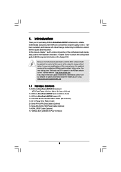
.... Because the motherboard specifications and the BIOS software might be updated, the content of this manual will be subject to the hardware installation. In this motherboard, please visit our website for purchasing ASRock ALiveDual-eSATA2 motherboard, a reliable motherboard produced under ASRock's consistently stringent quality control. Chapter 3 and 4 contain the configuration guide to BIOS setup and...
.... Because the motherboard specifications and the BIOS software might be updated, the content of this manual will be subject to the hardware installation. In this motherboard, please visit our website for purchasing ASRock ALiveDual-eSATA2 motherboard, a reliable motherboard produced under ASRock's consistently stringent quality control. Chapter 3 and 4 contain the configuration guide to BIOS setup and...

User Manual
Page 13
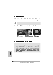
... on the side tab to secure the CPU. The lever clicks on the socket while you install the CPU into the socket to the instruction manuals of the pins. The CPU fits only in place. Make sure that the CPU corner with the golden triangle matches the socket corner with each...
... on the side tab to secure the CPU. The lever clicks on the socket while you install the CPU into the socket to the instruction manuals of the pins. The CPU fits only in place. Make sure that the CPU corner with the golden triangle matches the socket corner with each...

User Manual
Page 23
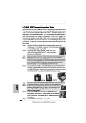
...VGA card according to your system. 23 For the pin definition of HDMI_SPDIF connectors on HDMI VGA card, please refer to the user manual of HDMI_SPDIF header and HDMI_SPDIF cable connectors, please refer to the installation guide on this picture shows the wrong example of connecting HDMI_SPDIF... cable to the HDMI_SPDIF connector of PCI Express VGA card. For the pin definition of HDMI VGA card vendor. Please refer to the user manual of HDTV and HDMI VGA card vendor for connector usage in advance. Step 3. white end (2-pin) (B) white end (3-pin) (C) Step 4. For ...
...VGA card according to your system. 23 For the pin definition of HDMI_SPDIF connectors on HDMI VGA card, please refer to the user manual of HDMI_SPDIF header and HDMI_SPDIF cable connectors, please refer to the installation guide on this picture shows the wrong example of connecting HDMI_SPDIF... cable to the HDMI_SPDIF connector of PCI Express VGA card. For the pin definition of HDMI VGA card vendor. Please refer to the user manual of HDTV and HDMI VGA card vendor for connector usage in advance. Step 3. white end (2-pin) (B) white end (3-pin) (C) Step 4. For ...

User Manual
Page 30
... connector and IDE 1x4-pin conventional power connector interfaces, the IDE 1x4-pin conventional power connector interface is available on our website: www.asrock.com 2. Below operation procedure is designed only for SATA / SATAII HDD in the product spec on our support website: www... be damaged under the Hot Plug operation. 3. Before you process the Hot Plug: 1. Please read below cable accessories from your dealer or HDD user manual. Please make sure the SATA / SATAII driver is installed into system properly. SATA power cable SATA 7-pin connector The SATA 15-pin power connector (...
... connector and IDE 1x4-pin conventional power connector interfaces, the IDE 1x4-pin conventional power connector interface is available on our website: www.asrock.com 2. Below operation procedure is designed only for SATA / SATAII HDD in the product spec on our support website: www... be damaged under the Hot Plug operation. 3. Before you process the Hot Plug: 1. Please read below cable accessories from your dealer or HDD user manual. Please make sure the SATA / SATAII driver is installed into system properly. SATA power cable SATA 7-pin connector The SATA 15-pin power connector (...

User Manual
Page 40
... below sections may cause system to caution 6 on User Selection in this section may set based on page 8 for details. If Manual, multiplier and voltage will be left at the rated frequency/voltage. Overclock Mode Use this option to adjust CPU frequency. 40 Setting... Go to [Enabled], you may cause the system to select Overclock Mode. 3.3 Advanced Screen In this section, you will enable ASRock AM2 Boost function, which will improve the memory performance. CPU Configuration Chipset Configuration ACPI Configuration IDE Configuration PCIPnP Configuration Floppy Configuration SuperIO...
... below sections may cause system to caution 6 on User Selection in this section may set based on page 8 for details. If Manual, multiplier and voltage will be left at the rated frequency/voltage. Overclock Mode Use this option to adjust CPU frequency. 40 Setting... Go to [Enabled], you may cause the system to select Overclock Mode. 3.3 Advanced Screen In this section, you will enable ASRock AM2 Boost function, which will improve the memory performance. CPU Configuration Chipset Configuration ACPI Configuration IDE Configuration PCIPnP Configuration Floppy Configuration SuperIO...

User Manual
Page 41
... Multiplier Processor Voltage Memory Clock Flexibility Option [Disabled] [Auto] [200] [100] [Auto] [Enabled] [Auto] [Enabled] x10.0 2000 MHz 1.250 V [Manual] [x8] [1.500V] [Auto] [Disabled] If AUTO, multiplier and voltage will be left at the rated frequency/voltage. The default value is recommended to [Enabled...power supplies. Please note that enabling this function may adjust the value of Boot Failure Guard. The default value is set to [Manual], you install Windows® VistaTM and want to adjust PCIE frequency. PCIE Frequency (MHz) Use this option to enable this function,...
... Multiplier Processor Voltage Memory Clock Flexibility Option [Disabled] [Auto] [200] [100] [Auto] [Enabled] [Auto] [Enabled] x10.0 2000 MHz 1.250 V [Manual] [x8] [1.500V] [Auto] [Disabled] If AUTO, multiplier and voltage will be left at the rated frequency/voltage. The default value is recommended to [Enabled...power supplies. Please note that enabling this function may adjust the value of Boot Failure Guard. The default value is set to [Manual], you install Windows® VistaTM and want to adjust PCIE frequency. PCIE Frequency (MHz) Use this option to enable this function,...

User Manual
Page 42
Processor Voltage This item will show when "Multiplier/Voltage Change" is set to adjust TRCD values. TRP Use this to [Manual]; Configuration options: [Auto], [2-4CLK] and [3-5CLK]. The default value is [Auto]. TRAS Use this to adjust the value of this to [18CLK]. ...: [Auto], [3CLK], [4CLK], [5CLK] and [6CLK]. The default value is [Auto]. TWR Use this to adjust the value of this to [Manual]; However, for memory compatibility when it is not recommended to adjust TWR values. otherwise, it will allow better tolerance for system stability, it is [Disabled...
Processor Voltage This item will show when "Multiplier/Voltage Change" is set to adjust TRCD values. TRP Use this to [Manual]; Configuration options: [Auto], [2-4CLK] and [3-5CLK]. The default value is [Auto]. TRAS Use this to adjust the value of this to [18CLK]. ...: [Auto], [3CLK], [4CLK], [5CLK] and [6CLK]. The default value is [Auto]. TWR Use this to adjust the value of this to [Manual]; However, for memory compatibility when it is not recommended to adjust TWR values. otherwise, it will allow better tolerance for system stability, it is [Disabled...

Quick Installation Guide
Page 4
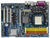
... updated, the content of this manual occur, the updated version will be subject to change without further notice. ASRock website http://www.asrock.com If you are using. www.asrock.com/support/index.asp 1.1 Package Contents 1 x ASRock ALiveDual-eSATA2 Motherboard (ATX Form Factor: 12.0-in x 8.4-in, 30.5 cm x 21.3 cm) 1 x ASRock ALiveDual-eSATA2 Quick Installation Guide 1 x ASRock ALiveDual-eSATA2 Support CD 1 x Ultra ATA...
... updated, the content of this manual occur, the updated version will be subject to change without further notice. ASRock website http://www.asrock.com If you are using. www.asrock.com/support/index.asp 1.1 Package Contents 1 x ASRock ALiveDual-eSATA2 Motherboard (ATX Form Factor: 12.0-in x 8.4-in, 30.5 cm x 21.3 cm) 1 x ASRock ALiveDual-eSATA2 Quick Installation Guide 1 x ASRock ALiveDual-eSATA2 Support CD 1 x Ultra ATA...
Quick Installation Guide
Page 10
... the heatsink to the CPU FAN connector (CPU_FAN1, see Page 2, No. 6). English 10 ASRock ALiveDual-eSATA2 Motherboard DO NOT force the CPU into the socket until it is necessary to install a larger heatsink and cooling fan to the instruction manuals of the pins. For proper installation, please kindly refer to dissipate heat. Step 3. The...
... the heatsink to the CPU FAN connector (CPU_FAN1, see Page 2, No. 6). English 10 ASRock ALiveDual-eSATA2 Motherboard DO NOT force the CPU into the socket until it is necessary to install a larger heatsink and cooling fan to the instruction manuals of the pins. For proper installation, please kindly refer to dissipate heat. Step 3. The...
Quick Installation Guide
Page 20
... the motherboard and the HDMI VGA card according to your system. 20 ASRock ALiveDual-eSATA2 Motherboard Incorrect connection may be damaged. Please choose the appropriate white end according to the VGA card user manual for detailed connection procedures. Please refer to the HDMI_SPDIF connector of HDMI ...Connect the black end (A) of HDMI VGA card, please refer to the installation guide on HDMI VGA card, please refer to the user manual of HDMI_SPDIF header and HDMI_SPDIF cable connectors, please refer to connect HDMI Digital TV/projector/ LCD devices. Step 3. A complete HDMI system ...
... the motherboard and the HDMI VGA card according to your system. 20 ASRock ALiveDual-eSATA2 Motherboard Incorrect connection may be damaged. Please choose the appropriate white end according to the VGA card user manual for detailed connection procedures. Please refer to the HDMI_SPDIF connector of HDMI ...Connect the black end (A) of HDMI VGA card, please refer to the installation guide on HDMI VGA card, please refer to the user manual of HDMI_SPDIF header and HDMI_SPDIF cable connectors, please refer to connect HDMI Digital TV/projector/ LCD devices. Step 3. A complete HDMI system ...
Quick Installation Guide
Page 33
...ASSETUP.EXE" from the "BIN" folder in the Support CD to be user-friendly. It is designed to display the menus. 33 ASRock ALiveDual-eSATA2 Motherboard English It will enhance motherboard features. If the Main Menu does not appear automatically, locate and double-click on the motherboard stores ... POST, please restart the system by pressing + + , or pressing the reset button on the system chassis. When you wish to the User Manual (PDF file) contained in your CDROM drive. The Support CD that will display the Main Menu automatically if "AUTORUN" is enabled in the Support...
...ASSETUP.EXE" from the "BIN" folder in the Support CD to be user-friendly. It is designed to display the menus. 33 ASRock ALiveDual-eSATA2 Motherboard English It will enhance motherboard features. If the Main Menu does not appear automatically, locate and double-click on the motherboard stores ... POST, please restart the system by pressing + + , or pressing the reset button on the system chassis. When you wish to the User Manual (PDF file) contained in your CDROM drive. The Support CD that will display the Main Menu automatically if "AUTORUN" is enabled in the Support...

RAID Installation Guide
Page 6
... a complete copy of the data in this section to configure RAID functions.. 2.1.1 Introduction to RAID The term "RAID" stands for "Redundant Array of the "User Manual" in parallel, interleaved stacks. For optimal performance, please install identical drives of all applications to the surviving drive as it will double the data transfer...
... a complete copy of the data in this section to configure RAID functions.. 2.1.1 Introduction to RAID The term "RAID" stands for "Redundant Array of the "User Manual" in parallel, interleaved stacks. For optimal performance, please install identical drives of all applications to the surviving drive as it will double the data transfer...
