
User Manual
Page 3
Contents 1 . Introduction 5 1.1 Package Contents 5 1.2 Specifications 6 1.3 Motherboard Layout 10 1.4 ASRock 8CH_eSATAII I/O Plus 11 2 . Installation 12 Pre-installation Precautions 12 2.1 CPU Installation 13 2.2 Installation of CPU Fan and Heatsink 13 2.3 Installation of Memory Modules (DIMM 14 2.4 Expansion Slots (PCI, PCI Express and AGP slots 16 2.5 Jumpers Setup 17 2.6 Onboard Headers and ...
Contents 1 . Introduction 5 1.1 Package Contents 5 1.2 Specifications 6 1.3 Motherboard Layout 10 1.4 ASRock 8CH_eSATAII I/O Plus 11 2 . Installation 12 Pre-installation Precautions 12 2.1 CPU Installation 13 2.2 Installation of CPU Fan and Heatsink 13 2.3 Installation of Memory Modules (DIMM 14 2.4 Expansion Slots (PCI, PCI Express and AGP slots 16 2.5 Jumpers Setup 17 2.6 Onboard Headers and ...

User Manual
Page 4
... 55 4.2.3 Utilities Menu 55 4.2.4 Contact Information 55 4 BIOS SETUP UTILITY 3 8 3.1 Introduction 38 3.1.1 BIOS Menu Bar 38 3.1.2 Navigation Keys 39 3.2 Main Screen 39 3.3 Advanced Screen 40 3.3.1 CPU Configuration 40 3.3.2 Chipset Configuration 43 3.3.3 ACPI Configuration 45 3.3.4 IDE Configuration 46 3.3.5 PCIPnP Configuration 48 3.3.6 Floppy Configuration 49 3.3.7 Super IO Configuration 49 3.3.8 USB Configuration 50 3.4 Hardware...
... 55 4.2.3 Utilities Menu 55 4.2.4 Contact Information 55 4 BIOS SETUP UTILITY 3 8 3.1 Introduction 38 3.1.1 BIOS Menu Bar 38 3.1.2 Navigation Keys 39 3.2 Main Screen 39 3.3 Advanced Screen 40 3.3.1 CPU Configuration 40 3.3.2 Chipset Configuration 43 3.3.3 ACPI Configuration 45 3.3.4 IDE Configuration 46 3.3.5 PCIPnP Configuration 48 3.3.6 Floppy Configuration 49 3.3.7 Super IO Configuration 49 3.3.8 USB Configuration 50 3.4 Hardware...
User Manual
Page 5
... the motherboard and step-bystep guide to change without further notice. ASRock website http://www.asrock.com If you are using. www.asrock.com/support/index.asp 1.1 Package Contents 1 x ASRock ALiveDual-eSATA2 Motherboard (ATX Form Factor: 12.0-in x 8.4-in, 30.5 cm x 21.3 cm) 1 x ASRock ALiveDual-eSATA2 Quick Installation Guide 1 x ASRock ALiveDual-eSATA2 Support CD 1 x Ultra ATA 66/100/133 IDE Ribbon Cable...
... the motherboard and step-bystep guide to change without further notice. ASRock website http://www.asrock.com If you are using. www.asrock.com/support/index.asp 1.1 Package Contents 1 x ASRock ALiveDual-eSATA2 Motherboard (ATX Form Factor: 12.0-in x 8.4-in, 30.5 cm x 21.3 cm) 1 x ASRock ALiveDual-eSATA2 Quick Installation Guide 1 x ASRock ALiveDual-eSATA2 Support CD 1 x Ultra ATA 66/100/133 IDE Ribbon Cable...

User Manual
Page 6
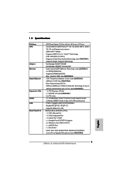
... 4) - capacity: 8GB (see CAUTION 2) - 4 x DDRII DIMM slots - Boot Failure Guard (B.F.G.) - Realtek RTL8111B / RTL8111C - Northbridge: NVIDIA® M1695 - Supports Wake-On-LAN ASRock 8CH_eSATAII I /O - Dual Channel DDRII Memory Technology (see CAUTION 3) - CPU Frequency Stepless Control (see CAUTION 7) - 3 x PCI slots - 7.1 CH Windows® VistaTM Premium Level Superior Audio (C-Media CM6501 Audio Codec with UAA...
... 4) - capacity: 8GB (see CAUTION 2) - 4 x DDRII DIMM slots - Boot Failure Guard (B.F.G.) - Realtek RTL8111B / RTL8111C - Northbridge: NVIDIA® M1695 - Supports Wake-On-LAN ASRock 8CH_eSATAII I /O - Dual Channel DDRII Memory Technology (see CAUTION 3) - CPU Frequency Stepless Control (see CAUTION 7) - 3 x PCI slots - 7.1 CH Windows® VistaTM Premium Level Superior Audio (C-Media CM6501 Audio Codec with UAA...

User Manual
Page 7
...support 4 x IDE devices) - 1 x Floppy connector - 1 x IR header - 1 x HDMI_SPDIF header - Supports "Plug and Play" - ACPI 1.1 Compliance Wake Up Events - SMBIOS 2.3.1 Support - CPU Quiet Fan - FCC, CE, WHQL Certificated 7 CD in header - Connector BIOS Feature Support CD Hardware Monitor OS Certifications - 2 x Serial ATA 1.5Gb/s connectors by NVIDIA®... NCQ, AHCI and "Hot Plug" functions (see CAUTION 12) - 4Mb AMI BIOS - Voltage Monitoring: +12V, +5V, +3.3V, Vcore - CPU/Chassis FAN connector - 24 pin ATX power connector - 4 pin 12V power connector - Supports jumperfree...
...support 4 x IDE devices) - 1 x Floppy connector - 1 x IR header - 1 x HDMI_SPDIF header - Supports "Plug and Play" - ACPI 1.1 Compliance Wake Up Events - SMBIOS 2.3.1 Support - CPU Quiet Fan - FCC, CE, WHQL Certificated 7 CD in header - Connector BIOS Feature Support CD Hardware Monitor OS Certifications - 2 x Serial ATA 1.5Gb/s connectors by NVIDIA®... NCQ, AHCI and "Hot Plug" functions (see CAUTION 12) - 4Mb AMI BIOS - Voltage Monitoring: +12V, +5V, +3.3V, Vcore - CPU/Chassis FAN connector - 24 pin ATX power connector - 4 pin 12V power connector - Supports jumperfree...

User Manual
Page 8
... If you plan to the operating system limitation, the actual memory size may cause permanent damage! We are not responsible for all CPU/DRAM configurations. This motherboard supports Untied Overclocking Technology. CAUTION! 1. However, we can not guarantee the system stability for possible damage caused... and mono modes. It may be less than the recommended CPU bus frequencies may not be done at your system is unstable after AM2 Boost function is no such limitation. 4. This motherboard supports ASRock AM2 Boost overclocking technology. Please check the table on page 14...
... If you plan to the operating system limitation, the actual memory size may cause permanent damage! We are not responsible for all CPU/DRAM configurations. This motherboard supports Untied Overclocking Technology. CAUTION! 1. However, we can not guarantee the system stability for possible damage caused... and mono modes. It may be less than the recommended CPU bus frequencies may not be done at your system is unstable after AM2 Boost function is no such limitation. 4. This motherboard supports ASRock AM2 Boost overclocking technology. Please check the table on page 14...

User Manual
Page 10
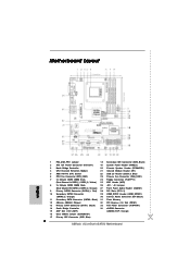
...CPU ATXPWR1 Top: SIDE SPK Center: REAR SPK Bottom: CTR BASS Top: LINE IN Center: FRONT Bottom: MIC IN LAN PHY 4Mb BIOS CD1 AUDIO CODEC 1 HDMI_SPDIF1 WIFI 1 AUDIO1 1 JR1 JL1 NVIDIA M1695 Chipset PCI EXPRESS SATA2 SATA1 JMicron JMB363 DDRII800 PCIE1 SATA FSB1GHz ALiveDual-eSATA2...System Panel Header (PANEL1) 3 North Bridge Controller 20 Chassis Speaker Header (SPEAKER1) 4 CPU Heatsink Retention Module 21 Infrared Module Header (IR1) 5 AM2 940-Pin CPU Socket 22 USB 2.0 Header (USB4_5, Blue) 6 CPU Fan Connector (CPU_FAN1) 23 Chassis Fan Connector (CHA_FAN1) 7 2 x 240-pin ...
...CPU ATXPWR1 Top: SIDE SPK Center: REAR SPK Bottom: CTR BASS Top: LINE IN Center: FRONT Bottom: MIC IN LAN PHY 4Mb BIOS CD1 AUDIO CODEC 1 HDMI_SPDIF1 WIFI 1 AUDIO1 1 JR1 JL1 NVIDIA M1695 Chipset PCI EXPRESS SATA2 SATA1 JMicron JMB363 DDRII800 PCIE1 SATA FSB1GHz ALiveDual-eSATA2...System Panel Header (PANEL1) 3 North Bridge Controller 20 Chassis Speaker Header (SPEAKER1) 4 CPU Heatsink Retention Module 21 Infrared Module Header (IR1) 5 AM2 940-Pin CPU Socket 22 USB 2.0 Header (USB4_5, Blue) 6 CPU Fan Connector (CPU_FAN1) 23 Chassis Fan Connector (CHA_FAN1) 7 2 x 240-pin ...

User Manual
Page 13
... The Socket Corner Small Triangle STEP 4: Push Down And Lock The Socket Lever 2.2 Installation of CPU Fan and Heatsink After you push down the socket lever to dissipate heat. Carefully insert the CPU into the socket until it is necessary to install a larger heatsink and cooling fan to secure... the CPU. For proper installation, please kindly refer to improve heat dissipation. Position the CPU directly above the socket such that it fits in place, press it firmly on the side tab to avoid...
... The Socket Corner Small Triangle STEP 4: Push Down And Lock The Socket Lever 2.2 Installation of CPU Fan and Heatsink After you push down the socket lever to dissipate heat. Carefully insert the CPU into the socket until it is necessary to install a larger heatsink and cooling fan to secure... the CPU. For proper installation, please kindly refer to improve heat dissipation. Position the CPU directly above the socket such that it fits in place, press it firmly on the side tab to avoid...

User Manual
Page 21
...pin ATX power supply. HDMI_SPDIF header, providing SPDIF audio output to HDMI VGA card, allows the system to do so will cause power up failure. CPU Fan Connector (4-pin CPU_FAN1) (see p.10, No. 29) 1 GND SPDIFOUT +5V Please note that it is necessary to connect a power ...13 ATX 12V Power Connector (4-pin ATX12V1) (see p.10, No. 2) HDMI_SPDIF Header (3-pin HDMI_SPDIF1) (see p.10, No. 6) 1 GND Please connect the CPU fan 2 3 +12V CPU_FAN_SPEED cable to this connector and 4 FAN_SPEED_CONTROL match the black wire to the ground pin. Pin 1-3 Connected 3-Pin Fan Installation ATX Power ...
...pin ATX power supply. HDMI_SPDIF header, providing SPDIF audio output to HDMI VGA card, allows the system to do so will cause power up failure. CPU Fan Connector (4-pin CPU_FAN1) (see p.10, No. 29) 1 GND SPDIFOUT +5V Please note that it is necessary to connect a power ...13 ATX 12V Power Connector (4-pin ATX12V1) (see p.10, No. 2) HDMI_SPDIF Header (3-pin HDMI_SPDIF1) (see p.10, No. 6) 1 GND Please connect the CPU fan 2 3 +12V CPU_FAN_SPEED cable to this connector and 4 FAN_SPEED_CONTROL match the black wire to the ground pin. Pin 1-3 Connected 3-Pin Fan Installation ATX Power ...

User Manual
Page 37
... install Windows® VistaTM or VistaTM 64-bit on JMicron® SATAII ports without RAID functions, please set the selection from [Auto] to [CPU, AGP, Async.]. You can operate under a more stable overclocking environment. B. STEP 2: Install Windows® VistaTM / VistaTM 64bit OS on page...install Windows® VistaTM / VistaTM 64-bit on NVIDIA® SATA ports without RAID functions, please follow below steps. Therefore, CPU FSB is untied during overclocking, FSB enjoys better margin due to [non-RAID]. Enter BIOS SETUP UTILITY Advanced screen IDE Configuration. Please...
... install Windows® VistaTM or VistaTM 64-bit on JMicron® SATAII ports without RAID functions, please set the selection from [Auto] to [CPU, AGP, Async.]. You can operate under a more stable overclocking environment. B. STEP 2: Install Windows® VistaTM / VistaTM 64bit OS on page...install Windows® VistaTM / VistaTM 64-bit on NVIDIA® SATA ports without RAID functions, please follow below steps. Therefore, CPU FSB is untied during overclocking, FSB enjoys better margin due to [non-RAID]. Enter BIOS SETUP UTILITY Advanced screen IDE Configuration. Please...

User Manual
Page 40
...refer to caution 6 on User Selection in this section may cause the system to malfunction. 3.3.1 CPU Configuration BIOS SETUP UTILITY Advanced CPU Configuration AM2 Boost Overclock Mode CPU Frequency (MHz) PCIE Frequency (MHz) Spread Spectrum Boot Failure Guard Cool' n' Quiet Secure ...CPU Frequency (MHz) Use this to select Overclock Mode. Setting wrong values in Setup. +F1 F9 F10 ESC Select Screen Select Item Change Option General Help Load Defaults Save and Exit Exit v02.54 (C) Copyright 1985-2003, American Megatrends, Inc. AM2 Boost If you set this section, you will enable ASRock...
...refer to caution 6 on User Selection in this section may cause the system to malfunction. 3.3.1 CPU Configuration BIOS SETUP UTILITY Advanced CPU Configuration AM2 Boost Overclock Mode CPU Frequency (MHz) PCIE Frequency (MHz) Spread Spectrum Boot Failure Guard Cool' n' Quiet Secure ...CPU Frequency (MHz) Use this to select Overclock Mode. Setting wrong values in Setup. +F1 F9 F10 ESC Select Screen Select Item Change Option General Help Load Defaults Save and Exit Exit v02.54 (C) Copyright 1985-2003, American Megatrends, Inc. AM2 Boost If you set this section, you will enable ASRock...

User Manual
Page 41
...it is [Enabled]. Boot Failure Guard Enable or disable the feature of Processor Multiplier and Processor Voltage. If you may reduce CPU voltage and memory frequency, and lead to [Auto] by AMD-V. Please set this item to keep the default value for reference... to enable or disable AMD's Cool 'n' QuietTM technology. Configuration options: [Enabled] and [Disabled]. BIOS SETUP UTILITY Advanced CPU Configuration AM2 Boost Overclock Mode CPU Frequency (MHz) PCIE Frequency (MHz) Spread Spectrum Boot Failure Guard Cool' n' Quiet Secure Virtual Machine Processor Maximum Multiplier ...
...it is [Enabled]. Boot Failure Guard Enable or disable the feature of Processor Multiplier and Processor Voltage. If you may reduce CPU voltage and memory frequency, and lead to [Auto] by AMD-V. Please set this item to keep the default value for reference... to enable or disable AMD's Cool 'n' QuietTM technology. Configuration options: [Enabled] and [Disabled]. BIOS SETUP UTILITY Advanced CPU Configuration AM2 Boost Overclock Mode CPU Frequency (MHz) PCIE Frequency (MHz) Spread Spectrum Boot Failure Guard Cool' n' Quiet Secure Virtual Machine Processor Maximum Multiplier ...

User Manual
Page 42
...and [400MHz (DDRII 800)]. You can be hidden. CAS Latency (CL) Use this item to adjust the means of the value depends on the CPU you adopt on this to adjust TRAS values. TRP Use this item. The default value is [Auto]. Configuration options: [Auto], [5CLK] to ... values. TWR Use this to [18CLK]. However, for memory compatibility when it is not recommended to adjust the value of the value depends on the CPU you adopt on this to adjust TWR values. Configuration options: [Auto], [3CLK], [4CLK], [5CLK] and [6CLK]. Configuration options: [Auto], [2CLK], [3CLK], [4CLK]...
...and [400MHz (DDRII 800)]. You can be hidden. CAS Latency (CL) Use this item to adjust the means of the value depends on the CPU you adopt on this to adjust TRAS values. TRP Use this item. The default value is [Auto]. Configuration options: [Auto], [5CLK] to ... values. TWR Use this to [18CLK]. However, for memory compatibility when it is not recommended to adjust the value of the value depends on the CPU you adopt on this to adjust TWR values. Configuration options: [Auto], [3CLK], [4CLK], [5CLK] and [6CLK]. Configuration options: [Auto], [2CLK], [3CLK], [4CLK]...

User Manual
Page 43
...[Auto], [2CLK], [3CLK], [4CLK], [5CLK], [6CLK], [7CLK], [8CLK] and [9CLK]. Configuration options: [Auto], [2T], [1T]. NB Link Speed CPU - SB Link Width [Auto] [Auto] [Auto] [Auto] DRAM Voltage AGP Voltage [Auto] [Auto] To set DRAM Voltage. +F1 F9 F10 ESC Select ...Auto] AGP Data Rate AGP Aperture Size AGP Fast Write AGP SideBand Address Primary Graphics Adapter [8X] [64 MB] [Disabled] [Enabled] [PCI] CPU - TWRRD Use this to adjust TWRRD values. Configuration options: [Auto], [1CLK], [2CLK] and [3CLK]. Configuration options: [Auto], [1CLK], [2CLK] and [3CLK].
...[Auto], [2CLK], [3CLK], [4CLK], [5CLK], [6CLK], [7CLK], [8CLK] and [9CLK]. Configuration options: [Auto], [2T], [1T]. NB Link Speed CPU - SB Link Width [Auto] [Auto] [Auto] [Auto] DRAM Voltage AGP Voltage [Auto] [Auto] To set DRAM Voltage. +F1 F9 F10 ESC Select ...Auto] AGP Data Rate AGP Aperture Size AGP Fast Write AGP SideBand Address Primary Graphics Adapter [8X] [64 MB] [Disabled] [Enabled] [PCI] CPU - TWRRD Use this to adjust TWRRD values. Configuration options: [Auto], [1CLK], [2CLK] and [3CLK]. Configuration options: [Auto], [1CLK], [2CLK] and [3CLK].

User Manual
Page 44
... Audio Select [Auto], [Enabled] or [Disabled] for graphics memory. Configuration options: [PCI], [PCI Express] and [AGP]. Configuration options: [8X], [4X]. CPU - AGP Voltage Use this field at the default value unless the installed AGP card's specifications requires other sizes. If you to NB link frequency. AGP... Fast Write This allows you selecting CPU to enable or disable the feature of the PCI memory address range used for the onboard UAA Audio feature. AGP SideBand ...
... Audio Select [Auto], [Enabled] or [Disabled] for graphics memory. Configuration options: [PCI], [PCI Express] and [AGP]. Configuration options: [8X], [4X]. CPU - AGP Voltage Use this field at the default value unless the installed AGP card's specifications requires other sizes. If you to NB link frequency. AGP... Fast Write This allows you selecting CPU to enable or disable the feature of the PCI memory address range used for the onboard UAA Audio feature. AGP SideBand ...

User Manual
Page 51
...]. BIOS SETUP UTILITY Main Advanced H/W Monitor Boot Security Exit Hardware Health Event Monitoring CPU Temperature M / B Temperature : 37 C / 98 F : 31 C / 87 F You are allowed to enable this function only when you to identify the temperature of the CPU temperature, motherboard temperature, CPU fan speed, chassis fan speed, and the critical voltage. The default value...
...]. BIOS SETUP UTILITY Main Advanced H/W Monitor Boot Security Exit Hardware Health Event Monitoring CPU Temperature M / B Temperature : 37 C / 98 F : 31 C / 87 F You are allowed to enable this function only when you to identify the temperature of the CPU temperature, motherboard temperature, CPU fan speed, chassis fan speed, and the critical voltage. The default value...
User Manual
Page 56
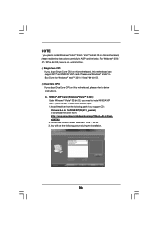
...\ALL in 1\nVIDIA\XP_2K(511_special) or download the driver from the following picture during the installation. 56 A. Install the driver from : http://www.asrock.com/mb/download.asp?Model=ALiveDualeSATA2 2. Please follow below steps. 1. Please use Windows® VistaTM In Box Driver for AGP card limitation. For ...Windows® 2000 / XP / XP 64-bit OS, there is no such limitation. (i) Single Core CPU: If you adopt Single Core CPU on this motherboard can support ATiTM and NVIDIA® AGP cards. NOTE If you plan to install Windows® VistaTM 32-bit /...
...\ALL in 1\nVIDIA\XP_2K(511_special) or download the driver from the following picture during the installation. 56 A. Install the driver from : http://www.asrock.com/mb/download.asp?Model=ALiveDualeSATA2 2. Please follow below steps. 1. Please use Windows® VistaTM In Box Driver for AGP card limitation. For ...Windows® 2000 / XP / XP 64-bit OS, there is no such limitation. (i) Single Core CPU: If you adopt Single Core CPU on this motherboard can support ATiTM and NVIDIA® AGP cards. NOTE If you plan to install Windows® VistaTM 32-bit /...
Quick Installation Guide
Page 2
... Header (PANEL1) 3 North Bridge Controller 20 Chassis Speaker Header (SPEAKER1) 4 CPU Heatsink Retention Module 21 Infrared Module Header (IR1) 5 AM2 940-Pin CPU Socket 22 USB 2.0 Header (USB4_5, Blue) 6 CPU Fan Connector (CPU_FAN1) 23 Chassis Fan Connector (CHA_FAN1) 7 2 x 240...JR1 / JL1 Jumper (Dual Channel B: DDRII_3, DDRII_4; Orange) 16 Clear CMOS Jumper (CLRCMOS1) 17 Primary IDE Connector (IDE1, Blue) 2 ASRock ALiveDual-eSATA2 Motherboard Orange) 27 Front Panel Audio Header (AUDIO1) 9 Primary SATAII Connector (SATAII_1; Red) 28 PCI Slots (PCI1- 3) 10 Secondary SATAII ...
... Header (PANEL1) 3 North Bridge Controller 20 Chassis Speaker Header (SPEAKER1) 4 CPU Heatsink Retention Module 21 Infrared Module Header (IR1) 5 AM2 940-Pin CPU Socket 22 USB 2.0 Header (USB4_5, Blue) 6 CPU Fan Connector (CPU_FAN1) 23 Chassis Fan Connector (CHA_FAN1) 7 2 x 240...JR1 / JL1 Jumper (Dual Channel B: DDRII_3, DDRII_4; Orange) 16 Clear CMOS Jumper (CLRCMOS1) 17 Primary IDE Connector (IDE1, Blue) 2 ASRock ALiveDual-eSATA2 Motherboard Orange) 27 Front Panel Audio Header (AUDIO1) 9 Primary SATAII Connector (SATAII_1; Red) 28 PCI Slots (PCI1- 3) 10 Secondary SATAII ...

Quick Installation Guide
Page 4
...ASRock ALiveDual-eSATA2 Support CD 1 x Ultra ATA 66/100/133 IDE Ribbon Cable (80-conductor) 1 x 3.5-in the Support CD. Introduction Thank you are using. 1. In case any modifications of this manual occur, the updated version will be subject to change without further notice. You may find the latest VGA cards and CPU... x HDMI_SPDIF Cable (Optional) 1 x "ASRock 8CH_eSATAII I/O Plus" I/O Shield 4 ASRock ALiveDual-eSATA2 Motherboard English This Quick Installation Guide contains introduction of the motherboard can be available on ASRock website as well. More detailed information of ...
...ASRock ALiveDual-eSATA2 Support CD 1 x Ultra ATA 66/100/133 IDE Ribbon Cable (80-conductor) 1 x 3.5-in the Support CD. Introduction Thank you are using. 1. In case any modifications of this manual occur, the updated version will be subject to change without further notice. You may find the latest VGA cards and CPU... x HDMI_SPDIF Cable (Optional) 1 x "ASRock 8CH_eSATAII I/O Plus" I/O Shield 4 ASRock ALiveDual-eSATA2 Motherboard English This Quick Installation Guide contains introduction of the motherboard can be available on ASRock website as well. More detailed information of ...
Quick Installation Guide
Page 5
... - 3 x PCI slots - 7.1 CH Windows® VistaTM Premium Level Superior Audio (C-Media CM6501 Audio Codec with UAA architecture) - ASRock AM2 Boost: ASRock Patented Technology to boost memory performance up to -Use USB 2.0 Ports - 1 x eSATAII Port - 1 x RJ-45 Port - ... 21.3 cm - Northbridge: NVIDIA® M1695 - ASRock U-COP (see CAUTION 8) English 5 ASRock ALiveDual-eSATA2 Motherboard Max. Supports Hyper-Transport Technology - CPU Frequency Stepless Control (see CAUTION 4) - Support DDRII800/667/533 - Supports Wake-On-LAN ASRock 8CH_eSATAII I /O - FSB 1000 MHz (2.0 GT/s) ...
... - 3 x PCI slots - 7.1 CH Windows® VistaTM Premium Level Superior Audio (C-Media CM6501 Audio Codec with UAA architecture) - ASRock AM2 Boost: ASRock Patented Technology to boost memory performance up to -Use USB 2.0 Ports - 1 x eSATAII Port - 1 x RJ-45 Port - ... 21.3 cm - Northbridge: NVIDIA® M1695 - ASRock U-COP (see CAUTION 8) English 5 ASRock ALiveDual-eSATA2 Motherboard Max. Supports Hyper-Transport Technology - CPU Frequency Stepless Control (see CAUTION 4) - Support DDRII800/667/533 - Supports Wake-On-LAN ASRock 8CH_eSATAII I /O - FSB 1000 MHz (2.0 GT/s) ...


