
User Manual
Page 2
...errors or omissions that may cause undesired operation. In no responsibility for identification or explanation and to the contents of this motherboard contains Perchlorate, a toxic substance controlled in Perchlorate Best Management Practices (BMP) regulations passed by the California Legislature. When...California, USA, please follow the related regulations in advance. With respect to the owners' benefit, without written consent of ASRock Inc. "Perchlorate Material-special handling may not be registered trademarks or copyrights of their respective companies, and are furnished ...
...errors or omissions that may cause undesired operation. In no responsibility for identification or explanation and to the contents of this motherboard contains Perchlorate, a toxic substance controlled in Perchlorate Best Management Practices (BMP) regulations passed by the California Legislature. When...California, USA, please follow the related regulations in advance. With respect to the owners' benefit, without written consent of ASRock Inc. "Perchlorate Material-special handling may not be registered trademarks or copyrights of their respective companies, and are furnished ...
User Manual
Page 3
Contents 1 Introduction 5 1.1 Package Contents 5 1.2 Specifications 6 1.3 Motherboard Layout 10 1.4 I/O Panel 11 2 Installation 12 2.1 Screw Holes 12 2.2 Pre-installation Precautions 12 2.3 Installation of Memory Modules (DIMM 13 2.4 Expansion Slot (PCI Slot 14 2.5 Jumpers ...
Contents 1 Introduction 5 1.1 Package Contents 5 1.2 Specifications 6 1.3 Motherboard Layout 10 1.4 I/O Panel 11 2 Installation 12 2.1 Screw Holes 12 2.2 Pre-installation Precautions 12 2.3 Installation of Memory Modules (DIMM 13 2.4 Expansion Slot (PCI Slot 14 2.5 Jumpers ...
User Manual
Page 5
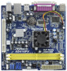
... version will be subject to BIOS setup and information of this motherboard, please visit our website for specific information about the model you for purchasing ASRock AD510PV / AD410PV motherboard, a reliable motherboard produced under ASRock's consistently stringent quality control. www.asrock.com/support/index.asp 1.1 Package Contents ASRock AD510PV / AD410PV Motherboard (Mini-ITX Form Factor: 6.7-in x 6.7-in, 17.0 cm x 17.0 cm...
... version will be subject to BIOS setup and information of this motherboard, please visit our website for specific information about the model you for purchasing ASRock AD510PV / AD410PV motherboard, a reliable motherboard produced under ASRock's consistently stringent quality control. www.asrock.com/support/index.asp 1.1 Package Contents ASRock AD510PV / AD410PV Motherboard (Mini-ITX Form Factor: 6.7-in x 6.7-in, 17.0 cm x 17.0 cm...
User Manual
Page 8
...® OS. 4. It is capable of "Hyper Threading Technology", please check page 33. 2. Just launch this motherboard offers stepless control, it is a user-friendly ASRock overclocking tool which allows you to save the new BIOS file to your BIOS only in Flash ROM. This... motherboard supports Untied Overclocking Technology. tied Overclocking Technology" on the same motherboard. 10. Your friends then can update your ...
...® OS. 4. It is capable of "Hyper Threading Technology", please check page 33. 2. Just launch this motherboard offers stepless control, it is a user-friendly ASRock overclocking tool which allows you to save the new BIOS file to your BIOS only in Flash ROM. This... motherboard supports Untied Overclocking Technology. tied Overclocking Technology" on the same motherboard. 10. Your friends then can update your ...

User Manual
Page 9
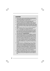
... shutdown. According to spray thermal grease between the CPU and the heatsink when you resume the system, please check if the CPU fan on the motherboard functions properly and unplug the power cord, then plug it back again. To meet the standard of the completed system shall be under 100 mA... for Energy Using Product, was a provision regulated by European Union to Intel's suggestion, the EuP ready power supply must meet EuP standard, an EuP ready motherboard and an EuP ready power supply are required.
... shutdown. According to spray thermal grease between the CPU and the heatsink when you resume the system, please check if the CPU fan on the motherboard functions properly and unplug the power cord, then plug it back again. To meet the standard of the completed system shall be under 100 mA... for Energy Using Product, was a provision regulated by European Union to Intel's suggestion, the EuP ready power supply must meet EuP standard, an EuP ready motherboard and an EuP ready power supply are required.
User Manual
Page 10
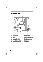
... Slot (PCI1) 6 ATX Power Connector (ATXPWR1) 16 Internal Audio Connector: CD1 (Black) 7 Chassis Fan Connector (CHA_FAN1) 17 Front Panel Audio Header 8 Secondary SATAII Connector (SATAII_2; 1.3 Motherboard Layout 1 2 34 5 17.0cm (6.7 in) 1 PS2_USB_PWR1 CPU_FAN1 Super IO 6 ErP/EuP Ready 17.0cm (6.7 in) DDRII_2 (64 bit, 240-piFnSmBod8ul0e)0 Design in Taipei DDRII_1 (64...
... Slot (PCI1) 6 ATX Power Connector (ATXPWR1) 16 Internal Audio Connector: CD1 (Black) 7 Chassis Fan Connector (CHA_FAN1) 17 Front Panel Audio Header 8 Secondary SATAII Connector (SATAII_2; 1.3 Motherboard Layout 1 2 34 5 17.0cm (6.7 in) 1 PS2_USB_PWR1 CPU_FAN1 Super IO 6 ErP/EuP Ready 17.0cm (6.7 in) DDRII_2 (64 bit, 240-piFnSmBod8ul0e)0 Design in Taipei DDRII_1 (64...

User Manual
Page 12
... the power cord from the power supply. Whenever you and damages to motherboard components. 2.1 Screw Holes Place screws into it on the carpet or the like. Chapter 2 Installation AD510PV / AD410PV is detached from the wall socket before installing or removing the motherboard. Make sure to static electricity, NEVER place your chassis to ensure...
... the power cord from the power supply. Whenever you and damages to motherboard components. 2.1 Screw Holes Place screws into it on the carpet or the like. Chapter 2 Installation AD510PV / AD410PV is detached from the wall socket before installing or removing the motherboard. Make sure to static electricity, NEVER place your chassis to ensure...

User Manual
Page 13
... the DIMM if you force the DIMM into DDR2 slot;otherwise, this motherboard and DIMM may be damaged. Step 2. notch break notch break The DIMM only fits in place and the DIMM is not allowed to install a DDR ... slot such that the notch on the DIMM matches the break on the slot. It is properly seated. 13 2.3 Installation of Memory Modules (DIMM) AD510PV / AD410PV motherboard provides two 240-pin DDR2 (Double Data Rate 2) DIMM slots.
... the DIMM if you force the DIMM into DDR2 slot;otherwise, this motherboard and DIMM may be damaged. Step 2. notch break notch break The DIMM only fits in place and the DIMM is not allowed to install a DDR ... slot such that the notch on the DIMM matches the break on the slot. It is properly seated. 13 2.3 Installation of Memory Modules (DIMM) AD510PV / AD410PV motherboard provides two 240-pin DDR2 (Double Data Rate 2) DIMM slots.

User Manual
Page 14
... use . Step 4. PCI slot: PCI slot is used to the chassis with the slot and press firmly until the card is completely seated on this motherboard. Step 3. Align the card connector with screws. 14 Step 2. Installing an expansion card Step 1. Before installing the expansion card, please make necessary hardware settings for...
... use . Step 4. PCI slot: PCI slot is used to the chassis with the slot and press firmly until the card is completely seated on this motherboard. Step 3. Align the card connector with screws. 14 Step 2. Installing an expansion card Step 1. Before installing the expansion card, please make necessary hardware settings for...
User Manual
Page 16
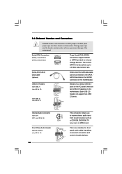
...the I/O panel, there are NOT jumpers. This connector allows you to the SATA / SATAII hard disk or the SATAII connector on the motherboard. Front Panel Audio Header (9-pin HD_AUDIO1) (see p.10, No. 8) SATAII_2 SATAII_1 These Serial ATAII (SATAII) connectors support SATAII or... P-5 P+5 GND DUMMY 1 GND P+4 P-4 USB_PWR CD-L GND GND CD-R CD1 Either end of the motherboard! 2.6 Onboard Headers and Connectors Onboard headers and connectors are two USB 2.0 headers on this motherboard. The current SATAII interface allows up to 3.0 Gb/s data transfer rate. Do NOT place jumper caps over...
...the I/O panel, there are NOT jumpers. This connector allows you to the SATA / SATAII hard disk or the SATAII connector on the motherboard. Front Panel Audio Header (9-pin HD_AUDIO1) (see p.10, No. 8) SATAII_2 SATAII_1 These Serial ATAII (SATAII) connectors support SATAII or... P-5 P+5 GND DUMMY 1 GND P+4 P-4 USB_PWR CD-L GND GND CD-R CD1 Either end of the motherboard! 2.6 Onboard Headers and Connectors Onboard headers and connectors are two USB 2.0 headers on this motherboard. The current SATAII interface allows up to 3.0 Gb/s data transfer rate. Do NOT place jumper caps over...

User Manual
Page 17
... and match the black wire to connect them for HD audio panel only. Set the Front Panel Control option from [Auto] to MIC2_L. Though this motherboard, please connect it to Pin 1-3. Connect Mic_IN (MIC) to [Enabled]. E. System Panel Header (9-pin PANEL1) (see p.10 No. 12) Chassis Speaker...to install your system. 2. Connect Ground (GND) to function correctly. 1. High Definition Audio supports Jack Sensing, but the panel wire on this motherboard provides 4-Pin CPU fan (Quiet Fan) support, the 3-Pin CPU fan still can work successfully even without the fan speed control function. If...
... and match the black wire to connect them for HD audio panel only. Set the Front Panel Control option from [Auto] to MIC2_L. Though this motherboard, please connect it to Pin 1-3. Connect Mic_IN (MIC) to [Enabled]. E. System Panel Header (9-pin PANEL1) (see p.10 No. 12) Chassis Speaker...to install your system. 2. Connect Ground (GND) to function correctly. 1. High Definition Audio supports Jack Sensing, but the panel wire on this motherboard provides 4-Pin CPU fan (Quiet Fan) support, the 3-Pin CPU fan still can work successfully even without the fan speed control function. If...

User Manual
Page 18
ATX Power Connector (24-pin ATXPWR1) (see p.10, No. 6) 12 24 Please connect an ATX power supply to this connector. 1 13 Though this motherboard provides 24-pin ATX power connector, 12 24 it can still work if you adopt a traditional 20-pin ATX power supply. To use the 20-pin ATX power supply, please plug your power supply along with Pin 1 and Pin 13. 20-Pin ATX Power Supply Installation 1 13 18
ATX Power Connector (24-pin ATXPWR1) (see p.10, No. 6) 12 24 Please connect an ATX power supply to this connector. 1 13 Though this motherboard provides 24-pin ATX power connector, 12 24 it can still work if you adopt a traditional 20-pin ATX power supply. To use the 20-pin ATX power supply, please plug your power supply along with Pin 1 and Pin 13. 20-Pin ATX Power Supply Installation 1 13 18
User Manual
Page 20
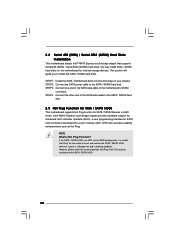
...the other end of the SATA data cable to the SATA / SATAII hard disk. 2.9 Hot Plug Function for SATA / SATAII HDDs This motherboard supports Hot Plug function for SATA host controllers developed thru a joint industry effort. Intel® NM10 Express south bridge chipset provides hardware support ...the SATA / SATAII hard disks into the SATA / SATAII HDD. 20 2.8 Serial ATA (SATA) / Serial ATAII (SATAII) Hard Disks Installation This motherboard adopts Intel® NM10 Express south bridge chipset that it is called "Hot Plug" for internal storage devices. If the SATA / SATAII HDDs are ...
...the other end of the SATA data cable to the SATA / SATAII hard disk. 2.9 Hot Plug Function for SATA / SATAII HDDs This motherboard supports Hot Plug function for SATA host controllers developed thru a joint industry effort. Intel® NM10 Express south bridge chipset provides hardware support ...the SATA / SATAII hard disks into the SATA / SATAII HDD. 20 2.8 Serial ATA (SATA) / Serial ATAII (SATAII) Hard Disks Installation This motherboard adopts Intel® NM10 Express south bridge chipset that it is called "Hot Plug" for internal storage devices. If the SATA / SATAII HDDs are ...
User Manual
Page 21
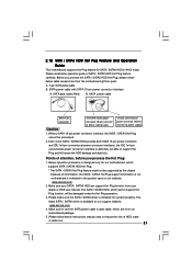
...power cable with SATA 15-pin power connector interface A. 2.10 SATA / SATAII HDD Hot Plug Feature and Operation Guide This motherboard supports Hot Plug feature for our motherboard, which supports SATA / SATAII HDD Hot Plug. * The SATA / SATAII Hot Plug feature might not be supported by ... Please read below instructions step by the chipset because of its limitation, the SATA / SATAII Hot Plug support information of our motherboard is available on our website: www.asrock.com 2. A. 7-pin SATA data cable B. SATA data cable (Red) B. Make sure your dealer or HDD user manual....
...power cable with SATA 15-pin power connector interface A. 2.10 SATA / SATAII HDD Hot Plug Feature and Operation Guide This motherboard supports Hot Plug feature for our motherboard, which supports SATA / SATAII HDD Hot Plug. * The SATA / SATAII Hot Plug feature might not be supported by ... Please read below instructions step by the chipset because of its limitation, the SATA / SATAII Hot Plug support information of our motherboard is available on our website: www.asrock.com 2. A. 7-pin SATA data cable B. SATA data cable (Red) B. Make sure your dealer or HDD user manual....

User Manual
Page 22
... Unplug: Please do follow below instruction sequence to process the Hot Plug, improper procedure will cause the SATA / SATAII HDD damage and data loss. the motherboard's SATAII connector. How to Hot Unplug a SATA / SATAII HDD: Points of attention, before you process the Hot Plug: Please do follow below instruction sequence to...
... Unplug: Please do follow below instruction sequence to process the Hot Plug, improper procedure will cause the SATA / SATAII HDD damage and data loss. the motherboard's SATAII connector. How to Hot Unplug a SATA / SATAII HDD: Points of attention, before you process the Hot Plug: Please do follow below instruction sequence to...
User Manual
Page 25
2.13 Untied Overclocking Technology This motherboard supports Untied Overclocking Technology, which means during overclocking, but PCI buse is untied during overclocking, FSB enjoys better margin due to fixed PCI bus. Before ...
2.13 Untied Overclocking Technology This motherboard supports Untied Overclocking Technology, which means during overclocking, but PCI buse is untied during overclocking, FSB enjoys better margin due to fixed PCI bus. Before ...

User Manual
Page 26
... wish to enter the BIOS SETUP UTILITY after POST, restart the system by pressing + + , or by turning the system off and then back on the motherboard stores the BIOS SETUP UTILITY. Because the BIOS software is constantly being updated, the following BIOS setup screens and descriptions are for reference purpose only...
... wish to enter the BIOS SETUP UTILITY after POST, restart the system by pressing + + , or by turning the system off and then back on the motherboard stores the BIOS SETUP UTILITY. Because the BIOS software is constantly being updated, the following BIOS setup screens and descriptions are for reference purpose only...

User Manual
Page 29
...(MHz) Use this option to adjust PCIE frequency. Please note that overclocing may cause damage to your CPU and motherboard. The default value is selected, the motherboard will detect the memory module(s) inserted and assigns appropriate frequency automatically. Overclock Mode Use this to Sub Screen F1...3.3 OC Tweaker Screen In the OC Tweaker screen, you like to save current setting as Overclocking may cause damage to your CPU and motherboard. Spread Spectrum This item should be [Auto] for better system stability. Boot Failure Guard Enable or disable the feature of Boot Failure...
...(MHz) Use this option to adjust PCIE frequency. Please note that overclocing may cause damage to your CPU and motherboard. The default value is selected, the motherboard will detect the memory module(s) inserted and assigns appropriate frequency automatically. Overclock Mode Use this to Sub Screen F1...3.3 OC Tweaker Screen In the OC Tweaker screen, you like to save current setting as Overclocking may cause damage to your CPU and motherboard. Spread Spectrum This item should be [Auto] for better system stability. Boot Failure Guard Enable or disable the feature of Boot Failure...
User Manual
Page 33
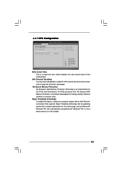
An IA-32 processor with an Intel Pentium® 4 processor that supports Hyper-Threading technology and an operating system that includes optimization for this motherboard. Set to execute code. Hyper Threading Technology To enable this feature, it requires a computer system with "No Execute (NX) Memory Protection" can prevent data pages ...
An IA-32 processor with an Intel Pentium® 4 processor that supports Hyper-Threading technology and an operating system that includes optimization for this motherboard. Set to execute code. Hyper Threading Technology To enable this feature, it requires a computer system with "No Execute (NX) Memory Protection" can prevent data pages ...
User Manual
Page 34
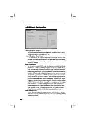
... Exit v02.54 (C) Copyright 1985-2005, American Megatrends, Inc. DVMT Mode Select Use this item if you set DVMT Mode Select as needed for the motherboard through efficient memory utilization. DVMT/FIXED Memory You are allowed to adjust the shared memory size in case of any add-on VGA card. Primary...
... Exit v02.54 (C) Copyright 1985-2005, American Megatrends, Inc. DVMT Mode Select Use this item if you set DVMT Mode Select as needed for the motherboard through efficient memory utilization. DVMT/FIXED Memory You are allowed to adjust the shared memory size in case of any add-on VGA card. Primary...

