User Manual
Page 3
... 5 1.2 Specifications 6 1.3 Motherboard Layout 10 1.4 I/O Panel 11 2 Installation 12 2.1 Screw Holes 12 2.2 Pre-installation Precautions 12 2.3 Installation of Memory Modules (DIMM 13 2.4 Expansion Slot (PCI Slot 14 2.5 Jumpers Setup 15 2.6 Onboard Headers and Connectors 16 2.7 SATAII Hard Disk Setup Guide 19 2.8 Serial ATA (SATA) / Serial ATAII (SATAII) Hard Disks Installation 20 2.9 Hot Plug Function for SATA / SATAII HDDs 20 2.10 SATA / SATAII HDD Hot Plug Feature and Operation Guide 21 2.11 Driver Installation Guide 23 2.12 Installing Windows® 7 / 7 64-bit / VistaTM...
... 5 1.2 Specifications 6 1.3 Motherboard Layout 10 1.4 I/O Panel 11 2 Installation 12 2.1 Screw Holes 12 2.2 Pre-installation Precautions 12 2.3 Installation of Memory Modules (DIMM 13 2.4 Expansion Slot (PCI Slot 14 2.5 Jumpers Setup 15 2.6 Onboard Headers and Connectors 16 2.7 SATAII Hard Disk Setup Guide 19 2.8 Serial ATA (SATA) / Serial ATAII (SATAII) Hard Disks Installation 20 2.9 Hot Plug Function for SATA / SATAII HDDs 20 2.10 SATA / SATAII HDD Hot Plug Feature and Operation Guide 21 2.11 Driver Installation Guide 23 2.12 Installing Windows® 7 / 7 64-bit / VistaTM...
User Manual
Page 7
...) - CPU Frequency Stepless Control (see CAUTION 8) - CPU Quiet Fan - Supports "Plug and Play" - ASRock OC Tuner (see CAUTION 12) * For detailed product information, please visit our website: http://www.asrock.com WARNING Please realize that there is a certain risk involved with overclocking, including adjusting the setting in the BIOS, applying Untied Overclocking Technology, or using the thirdparty overclocking tools. Chassis Temperature Sensing - Voltage Monitoring: +12V, +5V, +3.3V, Vcore OS - Supports Smart BIOS Support CD - Boot Failure...
...) - CPU Frequency Stepless Control (see CAUTION 8) - CPU Quiet Fan - Supports "Plug and Play" - ASRock OC Tuner (see CAUTION 12) * For detailed product information, please visit our website: http://www.asrock.com WARNING Please realize that there is a certain risk involved with overclocking, including adjusting the setting in the BIOS, applying Untied Overclocking Technology, or using the thirdparty overclocking tools. Chassis Temperature Sensing - Voltage Monitoring: +12V, +5V, +3.3V, Vcore OS - Supports Smart BIOS Support CD - Boot Failure...
User Manual
Page 8
... overclocking settings. Your friends then can update your hardware devices to access ASRock Instant Flash. Although this motherboard offers stepless control, it is a BIOS flash utility embedded in a few clicks without entering operating systems first like MS-DOS or Windows®. Due to get the best system performance under Windows® OS. 4. Just launch this utility, you to SATAII mode. CAUTION! 1. This motherboard supports Untied Overclocking Technology. Please read the "SATAII Hard Disk Setup Guide...
... overclocking settings. Your friends then can update your hardware devices to access ASRock Instant Flash. Although this motherboard offers stepless control, it is a BIOS flash utility embedded in a few clicks without entering operating systems first like MS-DOS or Windows®. Due to get the best system performance under Windows® OS. 4. Just launch this utility, you to SATAII mode. CAUTION! 1. This motherboard supports Untied Overclocking Technology. Please read the "SATAII Hard Disk Setup Guide...
User Manual
Page 10
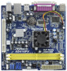
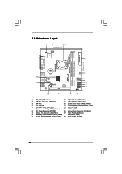
... In USB 2.0 T: USB2 B: USB3 CMOS Battery LAN USB 2.0 PHY T: USB0 Top: RJ-45 B: USB1 1 HD_AUDIO1 RoHS AUDIO CODEC CD1 PCI1 4Mb BIOS 16 15 14 CHA_FAN1 SATAII_2 SATAII_1 1 USB6_7 1 USB4_5 PLED PWRBTN 1 HDLED RESET PANEL 1 SPEAKER1 1 13 7 8 9 10 11 12 1 PS2_USB_PWR1 Jumper 10 USB 2.0 Header (USB6_7, Blue) 2 CPU Fan Connector (CPU_FAN1) 11 USB 2.0 Header (USB4_5, Blue) 3 CPU Fan 12 System Panel Header (PANEL1, White) 4 CPU Heatsink 13 Chassis Speaker Header (SPEAKER 1, White) 5 2 x 240-pin DDR2 DIMM Slots 14 BIOS SPI Chip (Dual Channel...
... In USB 2.0 T: USB2 B: USB3 CMOS Battery LAN USB 2.0 PHY T: USB0 Top: RJ-45 B: USB1 1 HD_AUDIO1 RoHS AUDIO CODEC CD1 PCI1 4Mb BIOS 16 15 14 CHA_FAN1 SATAII_2 SATAII_1 1 USB6_7 1 USB4_5 PLED PWRBTN 1 HDLED RESET PANEL 1 SPEAKER1 1 13 7 8 9 10 11 12 1 PS2_USB_PWR1 Jumper 10 USB 2.0 Header (USB6_7, Blue) 2 CPU Fan Connector (CPU_FAN1) 11 USB 2.0 Header (USB4_5, Blue) 3 CPU Fan 12 System Panel Header (PANEL1, White) 4 CPU Heatsink 13 Chassis Speaker Header (SPEAKER 1, White) 5 2 x 240-pin DDR2 DIMM Slots 14 BIOS SPI Chip (Dual Channel...
User Manual
Page 16
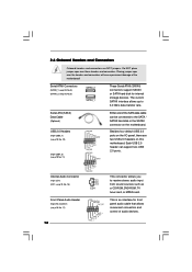
... MIC2_R MIC2_L This is an interface for internal storage devices. The current SATAII interface allows up to receive stereo audio input from sound sources such as a CD-ROM, DVD-ROM, TV tuner card, or MPEG card. Each USB 2.0 header can be connected to the SATA / SATAII hard disk or the SATAII connector on the motherboard. 2.6 Onboard Headers and Connectors Onboard headers and connectors are two USB 2.0 headers on this motherboard. Serial ATAII Connectors (SATAII_1: see p.10, No. 9) (SATAII_2: see...
... MIC2_R MIC2_L This is an interface for internal storage devices. The current SATAII interface allows up to receive stereo audio input from sound sources such as a CD-ROM, DVD-ROM, TV tuner card, or MPEG card. Each USB 2.0 header can be connected to the SATA / SATAII hard disk or the SATAII connector on the motherboard. 2.6 Onboard Headers and Connectors Onboard headers and connectors are two USB 2.0 headers on this motherboard. Serial ATAII Connectors (SATAII_1: see p.10, No. 9) (SATAII_2: see...

User Manual
Page 17
...Please connect a CPU fan cable to this motherboard, please connect it to Pin 1-3. Please connect the chassis speaker to the ground pin. Connect Mic_IN (MIC) to connect them for HD audio panel only. Enter BIOS Setup Utility. Though this header. Enter Advanced Settings, and then select Chipset Configuration. If you use AC'97 audio panel, please install it to the front panel audio header as below: A. D. E. Set the Front Panel Control option from [Auto] to function correctly. CPU Fan Connector (4-pin CPU_FAN1) (see p.10 No. 7) PLED+ PLEDPWRBTN# GND 1 DUMMY RESET...
...Please connect a CPU fan cable to this motherboard, please connect it to Pin 1-3. Please connect the chassis speaker to the ground pin. Connect Mic_IN (MIC) to connect them for HD audio panel only. Enter BIOS Setup Utility. Though this header. Enter Advanced Settings, and then select Chipset Configuration. If you use AC'97 audio panel, please install it to the front panel audio header as below: A. D. E. Set the Front Panel Control option from [Auto] to function correctly. CPU Fan Connector (4-pin CPU_FAN1) (see p.10 No. 7) PLED+ PLEDPWRBTN# GND 1 DUMMY RESET...
User Manual
Page 19
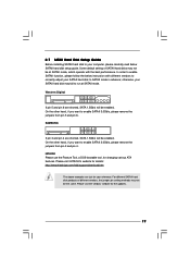
... SATAII hard disk setup guide. Please visit HITACHI's website for details: http://www.hitachigst.com/hdd/support/download.htm The above examples are shorted, SATA 1.5Gb/s will be the same. Western Digital 7531 8642 If pin 5 and pin 6 are just for the updates. 19 Please visit the vendors' website for your reference. Some default setting of different vendors, the jumper pin setting methods may not be enabled. On...
... SATAII hard disk setup guide. Please visit HITACHI's website for details: http://www.hitachigst.com/hdd/support/download.htm The above examples are shorted, SATA 1.5Gb/s will be the same. Western Digital 7531 8642 If pin 5 and pin 6 are just for the updates. 19 Please visit the vendors' website for your reference. Some default setting of different vendors, the jumper pin setting methods may not be enabled. On...
User Manual
Page 23
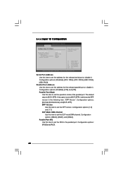
B. Set the option "SATA Operation Mode" to [IDE]. AHCI mode is not supported under Windows® XP / XP 64-bit OS. Therefore, the drivers you want to install Windows® XP / XP 64-bit OS on your SATA / SATAII HDDs without NCQ function STEP 1: Set up to bottom side to install those required drivers. Enter BIOS SETUP UTILITY Advanced screen Storage Configuration. Then, the drivers compatible to your system can work properly. 2.12 Installing Windows® 7 / 7 64-bit / VistaTM / VistaTM 64-bit / XP / XP...
B. Set the option "SATA Operation Mode" to [IDE]. AHCI mode is not supported under Windows® XP / XP 64-bit OS. Therefore, the drivers you want to install Windows® XP / XP 64-bit OS on your SATA / SATAII HDDs without NCQ function STEP 1: Set up to bottom side to install those required drivers. Enter BIOS SETUP UTILITY Advanced screen Storage Configuration. Then, the drivers compatible to your system can work properly. 2.12 Installing Windows® 7 / 7 64-bit / VistaTM / VistaTM 64-bit / XP / XP...
User Manual
Page 33
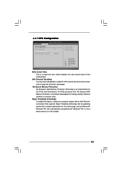
... is an enhancement to execute code. An IA-32 processor with an Intel Pentium® 4 processor that supports Hyper-Threading technology and an operating system that includes optimization for this motherboard. 3.4.1 CPU Configuration BIOS SETUP UTILITY Advanced CPU Configuration Ratio Actual Value CPU Thermal Throttling No-Execute Memory Protection Hyper Threading Technology 10 [Enabled] [Disabled] [Enabled] Enter to [Enabled] if using Microsoft® Windows® XP, or Linux kernel version 2.4.18 or higher. 33...
... is an enhancement to execute code. An IA-32 processor with an Intel Pentium® 4 processor that supports Hyper-Threading technology and an operating system that includes optimization for this motherboard. 3.4.1 CPU Configuration BIOS SETUP UTILITY Advanced CPU Configuration Ratio Actual Value CPU Thermal Throttling No-Execute Memory Protection Hyper Threading Technology 10 [Enabled] [Disabled] [Enabled] Enter to [Enabled] if using Microsoft® Windows® XP, or Linux kernel version 2.4.18 or higher. 33...
User Manual
Page 34
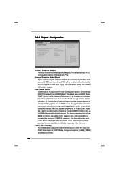
... primary graphics adapter. 3.4.2 Chipset Configuration BIOS SETUP UTILITY Advanced Chipset Settings Primary Graphics Adapter Internal Graphics Mode Select DVMT Mode Select DVMT/FIXED Memory Onboard HD Audio Front Panel OnBoard Lan [PCI] [Auto] [DVMT Mode] [Maximum DVMT] [Auto] [Enabled] [Enabled] Select the type of primary VGA in this amount to the graphics core, with other system components. DVMT Mode Select Use this option to adjust the shared memory size in case of multiple video controllers. +F1 F9 F10 ESC Select Screen Select Item Change Option General Help Load Defaults Save...
... primary graphics adapter. 3.4.2 Chipset Configuration BIOS SETUP UTILITY Advanced Chipset Settings Primary Graphics Adapter Internal Graphics Mode Select DVMT Mode Select DVMT/FIXED Memory Onboard HD Audio Front Panel OnBoard Lan [PCI] [Auto] [DVMT Mode] [Maximum DVMT] [Auto] [Enabled] [Enabled] Select the type of primary VGA in this amount to the graphics core, with other system components. DVMT Mode Select Use this option to adjust the shared memory size in case of multiple video controllers. +F1 F9 F10 ESC Select Screen Select Item Change Option General Help Load Defaults Save...

User Manual
Page 38
... the hard disk information into BIOS, use a disk utility, such as MO. Block (Multi-Sector Transfer) The default value of the Primary IDE hard disk drives to enable or disable the S.M.A.R.T. (Self-Monitoring, Analysis, and Reporting Technology) feature. PIO Mode Use this item is used for IDE CD/DVD drives. [ARMD]: This is [Auto]. LBA/Large Mode Use this item to active. [CD/DVD]: This is used for a hard disk > 512 MB under DOS and Windows; S.M.A.R.T. DMA Mode DMA capability...
... the hard disk information into BIOS, use a disk utility, such as MO. Block (Multi-Sector Transfer) The default value of the Primary IDE hard disk drives to enable or disable the S.M.A.R.T. (Self-Monitoring, Analysis, and Reporting Technology) feature. PIO Mode Use this item is used for IDE CD/DVD drives. [ARMD]: This is [Auto]. LBA/Large Mode Use this item to active. [CD/DVD]: This is used for a hard disk > 512 MB under DOS and Windows; S.M.A.R.T. DMA Mode DMA capability...
User Manual
Page 40
..., "EPP Version". 3.4.6 Super IO Configuration BIOS SETUP UTILITY Advanced Configure Super IO Chipset Serial Port Address Parallel Port Address Parallel Port Mode EPP Version ECP Mode DMA Channel Parallel Port IRQ [3F8 / IRQ4] [378] [ECP + EPP] [1.9] [DMA3] [IRQ7] Allow BIOS to set the EPP version. Parallel Port Mode Use this item to [ECP+EPP], it . Parallel Port IRQ Use this item to Enable or Disable Floppy Controller. +F1 F9 F10 ESC Select Screen Select Item Change Option General Help Load Defaults Save and...
..., "EPP Version". 3.4.6 Super IO Configuration BIOS SETUP UTILITY Advanced Configure Super IO Chipset Serial Port Address Parallel Port Address Parallel Port Mode EPP Version ECP Mode DMA Channel Parallel Port IRQ [3F8 / IRQ4] [378] [ECP + EPP] [1.9] [DMA3] [IRQ7] Allow BIOS to set the EPP version. Parallel Port Mode Use this item to [ECP+EPP], it . Parallel Port IRQ Use this item to Enable or Disable Floppy Controller. +F1 F9 F10 ESC Select Screen Select Item Change Option General Help Load Defaults Save and...
User Manual
Page 41
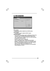
...select legacy support for USB devices. USB Controller Use this option to use of these four options: [Enabled] - If you have USB compatibility issue, it is [Enabled]. USB 2.0 Support Use this item to below descriptions for legacy USB. [Auto] - Please refer to enable or disable the USB 2.0 support. 3.4.7 USB Configuration BIOS SETUP UTILITY Advanced USB Configuration USB Controller USB 2.0 Support Legacy USB Support [Enabled] [Enabled] [Enabled] To enable or disable the onboard USB controllers. +F1 F9 F10 ESC Select Screen Select Item Change Option General Help Load Defaults...
...select legacy support for USB devices. USB Controller Use this option to use of these four options: [Enabled] - If you have USB compatibility issue, it is [Enabled]. USB 2.0 Support Use this item to below descriptions for legacy USB. [Auto] - Please refer to enable or disable the USB 2.0 support. 3.4.7 USB Configuration BIOS SETUP UTILITY Advanced USB Configuration USB Controller USB 2.0 Support Legacy USB Support [Enabled] [Enabled] [Enabled] To enable or disable the onboard USB controllers. +F1 F9 F10 ESC Select Screen Select Item Change Option General Help Load Defaults...
User Manual
Page 44
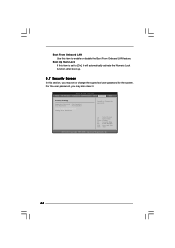
... item is set to [On], it . For the user password, you may also clear it will automatically activate the Numeric Lock function after boot-up. 3.7 Security Screen In this item to enable or disable the Boot From Onboard LAN feature. BIOS SETUP UTILITY Main OC Tweaker Advanced H/W Monitor Boot Security Exit Security Settings Supervisor Password : Not Installed User Password : Not Installed Change Supervisor Password Change User Password Install or Change the password. Select Screen Select Item Enter Change F1 General Help F9 Load Defaults F10 Save...
... item is set to [On], it . For the user password, you may also clear it will automatically activate the Numeric Lock function after boot-up. 3.7 Security Screen In this item to enable or disable the Boot From Onboard LAN feature. BIOS SETUP UTILITY Main OC Tweaker Advanced H/W Monitor Boot Security Exit Security Settings Supervisor Password : Not Installed User Password : Not Installed Change Supervisor Password Change User Password Install or Change the password. Select Screen Select Item Enter Change F1 General Help F9 Load Defaults F10 Save...
User Manual
Page 46
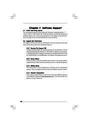
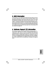
... 64-bit. The CD automatically displays the Main Menu if "AUTORUN" is enabled in this chapter for further information. 46 or you need to contact ASRock or want to know more information. 4.2 Support CD Information The Support CD that came with the motherboard contains necessary drivers and useful utilities that the motherboard supports. Please install the necessary drivers to your CD-ROM drive. Refer to activate the devices. 4.2.3 Utilities Menu The Utilities Menu...
... 64-bit. The CD automatically displays the Main Menu if "AUTORUN" is enabled in this chapter for further information. 46 or you need to contact ASRock or want to know more information. 4.2 Support CD Information The Support CD that came with the motherboard contains necessary drivers and useful utilities that the motherboard supports. Please install the necessary drivers to your CD-ROM drive. Refer to activate the devices. 4.2.3 Utilities Menu The Utilities Menu...
Quick Installation Guide
Page 6
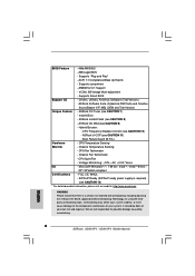
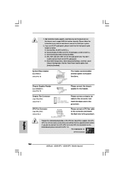
... 6 ASRock AD510PV / AD410PV Motherboard BIOS Feature - 4Mb AMI BIOS - Drivers, Utilities, AntiVirus Software (Trial Version), ASRock Software Suite (CyberLink DVD Suite and Creative Sound Blaster X-Fi MB) (OEM and Trial Version) Unique Feature - Boot Failure Guard (B.F.G.) Hardware - CPU Quiet Fan - FCC, CE, WHQL - Supports jumperfree - CPU Fan Tachometer - ErP/EuP Ready (ErP/EuP ready power supply is required) (see CAUTION 9) - It should be done at your system. AMI Legal BIOS - Supports "Plug and Play" - ACPI 1.1 Compliance Wake Up...
... 6 ASRock AD510PV / AD410PV Motherboard BIOS Feature - 4Mb AMI BIOS - Drivers, Utilities, AntiVirus Software (Trial Version), ASRock Software Suite (CyberLink DVD Suite and Creative Sound Blaster X-Fi MB) (OEM and Trial Version) Unique Feature - Boot Failure Guard (B.F.G.) Hardware - CPU Quiet Fan - FCC, CE, WHQL - Supports jumperfree - CPU Fan Tachometer - ErP/EuP Ready (ErP/EuP ready power supply is required) (see CAUTION 9) - It should be done at your system. AMI Legal BIOS - Supports "Plug and Play" - ACPI 1.1 Compliance Wake Up...
Quick Installation Guide
Page 7
... MS-DOS or Windows®. Please read the "SATAII Hard Disk Setup Guide" on page 19 of . The maximum shared memory size is defined by hardware monitor function and overclock your system by the chipset vendor and is a user-friendly ASRock overclocking tool which allows you can press key during the POST or press key to BIOS setup menu to SATAII mode. About the setting of "Hyper Threading Technology", please check page...
... MS-DOS or Windows®. Please read the "SATAII Hard Disk Setup Guide" on page 19 of . The maximum shared memory size is defined by hardware monitor function and overclock your system by the chipset vendor and is a user-friendly ASRock overclocking tool which allows you can press key during the POST or press key to BIOS setup menu to SATAII mode. About the setting of "Hyper Threading Technology", please check page...
Quick Installation Guide
Page 14
...to MIC2_L. Enter BIOS Setup Utility. 1. B. Connect Ground (GND) to [Enabled]. Set the Front Panel Control option from [Auto] to Ground (GND). System Panel Header (9-pin PANEL1) (see p.2 No. 2) 4 3 2 1 Please connect the chassis speaker to this motherboard, please connect it to this motherboard provides 4-Pin CPU fan (Quiet Fan) support, the 3-Pin CPU fan still can work successfully even without the fan speed control function. Please connect a CPU fan cable to the front panel audio header as below: A. Though this connector and match the black wire to function correctly...
...to MIC2_L. Enter BIOS Setup Utility. 1. B. Connect Ground (GND) to [Enabled]. Set the Front Panel Control option from [Auto] to Ground (GND). System Panel Header (9-pin PANEL1) (see p.2 No. 2) 4 3 2 1 Please connect the chassis speaker to this motherboard, please connect it to this motherboard provides 4-Pin CPU fan (Quiet Fan) support, the 3-Pin CPU fan still can work successfully even without the fan speed control function. Please connect a CPU fan cable to the front panel audio header as below: A. Though this connector and match the black wire to function correctly...
Quick Installation Guide
Page 17
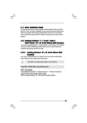
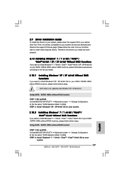
...ASRock AD510PV / AD410PV Motherboard English Enter BIOS SETUP UTILITY Advanced screen Storage Configuration. Enter BIOS SETUP UTILITY Advanced screen Storage Configuration. B. Then, the drivers compatible to install Windows® 7 / 7 64-bit / VistaTM / VistaTM 64-bit OS on your SATA / SATAII HDDs without RAID functions, please follow below steps. Using SATA / SATAII HDDs without NCQ function STEP 1: Set up BIOS. Using SATA / SATAII HDDs without NCQ function STEP 1: Set up to bottom side to your optical drive first. A. AHCI mode is not supported under Windows...
...ASRock AD510PV / AD410PV Motherboard English Enter BIOS SETUP UTILITY Advanced screen Storage Configuration. Enter BIOS SETUP UTILITY Advanced screen Storage Configuration. B. Then, the drivers compatible to install Windows® 7 / 7 64-bit / VistaTM / VistaTM 64-bit OS on your SATA / SATAII HDDs without RAID functions, please follow below steps. Using SATA / SATAII HDDs without NCQ function STEP 1: Set up BIOS. Using SATA / SATAII HDDs without NCQ function STEP 1: Set up to bottom side to your optical drive first. A. AHCI mode is not supported under Windows...
Quick Installation Guide
Page 19
... systems: 7 / 7 64-bit / VistaTM / VistaTM 64-bit / XP / XP 64-bit. If the Main Menu does not appear automatically, locate and doubleclick on the file "ASSETUP.EXE" from the BIN folder in the Support CD to enter BIOS Setup after POST, please restart the system by pressing + + , or pressing the reset button on the motherboard stores BIOS Setup Utility. 3. When you wish to display the menus. 19 ASRock AD510PV / AD410PV Motherboard English
... systems: 7 / 7 64-bit / VistaTM / VistaTM 64-bit / XP / XP 64-bit. If the Main Menu does not appear automatically, locate and doubleclick on the file "ASSETUP.EXE" from the BIN folder in the Support CD to enter BIOS Setup after POST, please restart the system by pressing + + , or pressing the reset button on the motherboard stores BIOS Setup Utility. 3. When you wish to display the menus. 19 ASRock AD510PV / AD410PV Motherboard English


