
User Manual
Page 7
... LAN 10/100/1000 Mb/s - Supports PXE I /O SATA3 USB 3.0 Connector - 7.1 CH HD Audio with LED (ACT/LINK LED and SPEED LED) - Realtek RTL8111E - CPU/Chassis/Power FAN connector - 24 pin ATX power connector - 8 pin 12V power connector - Front panel audio connector - 3 x USB 2.0 headers (support 6 USB 2.0 ports) 7 Supports LAN Cable Detection - Supports THX TruStudioTM -
... LAN 10/100/1000 Mb/s - Supports PXE I /O SATA3 USB 3.0 Connector - 7.1 CH HD Audio with LED (ACT/LINK LED and SPEED LED) - Realtek RTL8111E - CPU/Chassis/Power FAN connector - 24 pin ATX power connector - 8 pin 12V power connector - Front panel audio connector - 3 x USB 2.0 headers (support 6 USB 2.0 ports) 7 Supports LAN Cable Detection - Supports THX TruStudioTM -
User Manual
Page 12
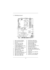
...MIC IN LAN Top: Center: Designed in Taipei AUDIO CODEC Super I/O HD_AUDIO1 1 HDMI_SPDIF1 1 32 31 CHA_FAN2 CHA_FAN3 PCIE1 A55 Pro3 Dual Graphics PCIE2 USB 3.0 CMOS BATTERY PCI1 ErP/EuP Ready XFast USB PCIE3 RoHS PCI2 CLRCMOS1 1 1 PCI3 COM1 IR1 1 USB6_7...12V Power Connector (ATX12V1) 21 SATA2 Connector (SATA2_1, Blue) 3 CPU Heatsink Retention Module 22 Chassis Fan Connector (CHA_FAN1) 4 CPU Socket 23 USB 2.0 Header (USB10_11, Blue) 5 CPU Fan Connector (CPU_FAN1) 24 SPI Flash Memory (32Mb) 6 CPU Fan Connector (CPU_FAN2) 25 USB 2.0 Header (USB8_9, Blue) 7 2 x 240-pin...
...MIC IN LAN Top: Center: Designed in Taipei AUDIO CODEC Super I/O HD_AUDIO1 1 HDMI_SPDIF1 1 32 31 CHA_FAN2 CHA_FAN3 PCIE1 A55 Pro3 Dual Graphics PCIE2 USB 3.0 CMOS BATTERY PCI1 ErP/EuP Ready XFast USB PCIE3 RoHS PCI2 CLRCMOS1 1 1 PCI3 COM1 IR1 1 USB6_7...12V Power Connector (ATX12V1) 21 SATA2 Connector (SATA2_1, Blue) 3 CPU Heatsink Retention Module 22 Chassis Fan Connector (CHA_FAN1) 4 CPU Socket 23 USB 2.0 Header (USB10_11, Blue) 5 CPU Fan Connector (CPU_FAN1) 24 SPI Flash Memory (32Mb) 6 CPU Fan Connector (CPU_FAN2) 25 USB 2.0 Header (USB8_9, Blue) 7 2 x 240-pin...
User Manual
Page 33
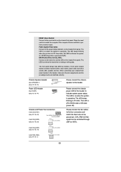
... in S1 sleep state. PLED (System Power LED): Connect to the ground pin. The LED is operating. Chassis Speaker Header (4-pin SPEAKER 1) (see p.12 No. 15) Power LED Header (3-pin PLED1) (see p.12 No. 14) 1 PLEDPLED+ PLED+ Chassis and Power Fan Connectors (4-pin CHA_FAN1) (see p.12 No. 22) FAN_SPEED_CONTROL GND +12V CHA_FAN_SPEED (3-pin CHA_FAN2) (see p.12 No. 1) 33 RESET...
... in S1 sleep state. PLED (System Power LED): Connect to the ground pin. The LED is operating. Chassis Speaker Header (4-pin SPEAKER 1) (see p.12 No. 15) Power LED Header (3-pin PLED1) (see p.12 No. 14) 1 PLEDPLED+ PLED+ Chassis and Power Fan Connectors (4-pin CHA_FAN1) (see p.12 No. 22) FAN_SPEED_CONTROL GND +12V CHA_FAN_SPEED (3-pin CHA_FAN2) (see p.12 No. 1) 33 RESET...

User Manual
Page 34
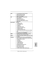
... power supply along with Pin 1 and Pin 5. 4-Pin ATX 12V Power Supply Installation 1 5 Serial port Header (9-pin COM1) (see p.12 No. 2) 4 8 1 5 Please connect an ATX 12V power supply to this connector. Though this motherboard provides 8-pin ATX 12V power connector, it can still work if you adopt a traditional 4-pin ATX 12V power supply. Pin 1-3 Connected 3-Pin Fan Installation (3-pin CPU_FAN2) (see p.12 No. 6) GND +12V CPU_FAN_SPEED ATX Power Connector (24-pin...
... power supply along with Pin 1 and Pin 5. 4-Pin ATX 12V Power Supply Installation 1 5 Serial port Header (9-pin COM1) (see p.12 No. 2) 4 8 1 5 Please connect an ATX 12V power supply to this connector. Though this motherboard provides 8-pin ATX 12V power connector, it can still work if you adopt a traditional 4-pin ATX 12V power supply. Pin 1-3 Connected 3-Pin Fan Installation (3-pin CPU_FAN2) (see p.12 No. 6) GND +12V CPU_FAN_SPEED ATX Power Connector (24-pin...

Quick Installation Guide
Page 2
...Consumer Infrared Module Header (CIR1) 8 2 x 240-pin DDR3 DIMM Slots 28 Infrared Module Header (IR1) (Dual Channel B: DDR3_A2, DDR3_B2; White) 18 SATA2 Connector (SATA2_5, Blue) 39 Chassis Fan Connector (CHA_FAN2) 19 SATA2 Connector (SATA2_4, Blue) 2 ASRock A55 Pro3 Motherboard English Blue) 15 Chassis Speaker Header (SPEAKER 1,...21 20 30.5cm (12.0-in) 9 10 11 12 13 14 15 16 17 18 19 1 Power Fan Connector (PWR_FAN1) 20 SATA2 Connector (SATA2_2, Blue) 2 ATX 12V Power Connector (ATX12V1) 21 SATA2 Connector (SATA2_1, Blue) 3 CPU Heatsink Retention Module 22 Chassis Fan Connector ...
...Consumer Infrared Module Header (CIR1) 8 2 x 240-pin DDR3 DIMM Slots 28 Infrared Module Header (IR1) (Dual Channel B: DDR3_A2, DDR3_B2; White) 18 SATA2 Connector (SATA2_5, Blue) 39 Chassis Fan Connector (CHA_FAN2) 19 SATA2 Connector (SATA2_4, Blue) 2 ASRock A55 Pro3 Motherboard English Blue) 15 Chassis Speaker Header (SPEAKER 1,...21 20 30.5cm (12.0-in) 9 10 11 12 13 14 15 16 17 18 19 1 Power Fan Connector (PWR_FAN1) 20 SATA2 Connector (SATA2_2, Blue) 2 ATX 12V Power Connector (ATX12V1) 21 SATA2 Connector (SATA2_1, Blue) 3 CPU Heatsink Retention Module 22 Chassis Fan Connector ...
Quick Installation Guide
Page 7
...Protection (Realtek ALC892 Audio Codec) - Front panel audio connector - 3 x USB 2.0 headers (support 6 USB 2.0 ports) English 7 ASRock A55 Pro3 Motherboard Supports LAN Cable Detection - CPU/Chassis/Power FAN connector - 24 pin ATX power connector - 8 pin 12V power connector - PCIE x1 Gigabit LAN 10/100/1000 Mb/s - Supports PXE I /O SATA3 USB 3.0 Connector - 7.1 CH HD Audio ... 1 and RAID 10), NCQ, AHCI and "Hot Plug" functions - 2 x SATA3 6.0Gb/s connectors - 1 x IR header - 1 x CIR header - 1 x COM port header - 1 x HDMI_SPDIF header - 1 x Power LED header - Supports Wake-On-LAN -
...Protection (Realtek ALC892 Audio Codec) - Front panel audio connector - 3 x USB 2.0 headers (support 6 USB 2.0 ports) English 7 ASRock A55 Pro3 Motherboard Supports LAN Cable Detection - CPU/Chassis/Power FAN connector - 24 pin ATX power connector - 8 pin 12V power connector - PCIE x1 Gigabit LAN 10/100/1000 Mb/s - Supports PXE I /O SATA3 USB 3.0 Connector - 7.1 CH HD Audio ... 1 and RAID 10), NCQ, AHCI and "Hot Plug" functions - 2 x SATA3 6.0Gb/s connectors - 1 x IR header - 1 x CIR header - 1 x COM port header - 1 x HDMI_SPDIF header - 1 x Power LED header - Supports Wake-On-LAN -

Quick Installation Guide
Page 30
... front panel. RESET (Reset Switch): Connect to perform a normal restart. HDLED (Hard Drive Activity LED): Connect to this header. Chassis Speaker Header (4-pin SPEAKER 1) (see p.2 No. 15) Power LED Header (3-pin PLED1) (see p.2 No. 14) 1 PLEDPLED+ PLED+ Chassis and Power Fan Connectors (4-pin CHA_FAN1) (see p.2 No. 22) FAN_SPEED_CONTROL GND +12V CHA_FAN_SPEED (3-pin CHA_FAN2) (see p.2 No. 1) 30 ASRock A55 Pro3 Motherboard
... front panel. RESET (Reset Switch): Connect to perform a normal restart. HDLED (Hard Drive Activity LED): Connect to this header. Chassis Speaker Header (4-pin SPEAKER 1) (see p.2 No. 15) Power LED Header (3-pin PLED1) (see p.2 No. 14) 1 PLEDPLED+ PLED+ Chassis and Power Fan Connectors (4-pin CHA_FAN1) (see p.2 No. 22) FAN_SPEED_CONTROL GND +12V CHA_FAN_SPEED (3-pin CHA_FAN2) (see p.2 No. 1) 30 ASRock A55 Pro3 Motherboard

Quick Installation Guide
Page 31
... 31 ASRock A55 Pro3 Motherboard If you plan to connect the 3-Pin CPU fan to the CPU fan connector on this motherboard, please connect it can still work if you adopt a traditional 4-pin ATX 12V power supply. To use the 4 8 4-pin ATX power supply, please plug your power supply along with Pin 1 and Pin 13. 20-Pin ATX Power Supply Installation 1 13 ATX 12V Power Connector (8-pin...
... 31 ASRock A55 Pro3 Motherboard If you plan to connect the 3-Pin CPU fan to the CPU fan connector on this motherboard, please connect it can still work if you adopt a traditional 4-pin ATX 12V power supply. To use the 4 8 4-pin ATX power supply, please plug your power supply along with Pin 1 and Pin 13. 20-Pin ATX Power Supply Installation 1 13 ATX 12V Power Connector (8-pin...


