
User Manual
Page 7
...- FCC, CE, WHQL - ErP/EuP Ready (ErP/EuP ready power supply is required) * For detailed product information, please visit our website: http://www.asrock.com 7 Rear Panel I/O I/O Panel - 1 x PS/2 Mouse Port - 1 x PS/2 Keyboard Port - 1 x D-Sub Port - 1 x ... CIR header - 1 x COM port header - 1 x HDMI_SPDIF header - 1 x Power LED header - 1 x CPU Fan connector (4-pin) - 2 x Chassis Fan connectors (2 x 4-pin) - 24 pin ATX power connector - 8 pin 12V power connector - CPU Quiet Fan - Front panel audio connector - 2 x USB 2.0 headers (support 4 USB 2.0 ports) BIOS Feature -...
...- FCC, CE, WHQL - ErP/EuP Ready (ErP/EuP ready power supply is required) * For detailed product information, please visit our website: http://www.asrock.com 7 Rear Panel I/O I/O Panel - 1 x PS/2 Mouse Port - 1 x PS/2 Keyboard Port - 1 x D-Sub Port - 1 x ... CIR header - 1 x COM port header - 1 x HDMI_SPDIF header - 1 x Power LED header - 1 x CPU Fan connector (4-pin) - 2 x Chassis Fan connectors (2 x 4-pin) - 24 pin ATX power connector - 8 pin 12V power connector - CPU Quiet Fan - Front panel audio connector - 2 x USB 2.0 headers (support 4 USB 2.0 ports) BIOS Feature -...

User Manual
Page 11
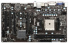
... DDR3_B1 (64 bit, 240-pin module) DDR3_A1 (64 bit, 240-pin module) SOCKET FM1 DVI1 ATXPWR1 USB 2.0 T: USB0 B: USB1 Dual Graphics USB 2.0 T: USB4 B: USB5 7 DX11 RJ-45 LAN USB 2.0 T: USB2 B: USB3 Top: Line In Center: Front Bottom: Mic In 8 33 PCIE1 RoHS A55 Pro SATA_1 SATA_2 9 32 PCIE2 ...13 14 15 16 17 18 27 26 25 24 23 22 21 20 19 1 ATX 12V Power Connector (ATX12V1) 2 CPU Socket 3 CPU Heatsink Retention Module 4 CPU Fan Connector (CPU_FAN1) 5 Chassis Fan Connector (CHA_FAN2) 6 2 x 240-pin DDR3 DIMM Slots (Dual Channel: DDR3_A1, DDR3_B1) 7 ATX Power Connector (ATXPWR1) 8 ...
... DDR3_B1 (64 bit, 240-pin module) DDR3_A1 (64 bit, 240-pin module) SOCKET FM1 DVI1 ATXPWR1 USB 2.0 T: USB0 B: USB1 Dual Graphics USB 2.0 T: USB4 B: USB5 7 DX11 RJ-45 LAN USB 2.0 T: USB2 B: USB3 Top: Line In Center: Front Bottom: Mic In 8 33 PCIE1 RoHS A55 Pro SATA_1 SATA_2 9 32 PCIE2 ...13 14 15 16 17 18 27 26 25 24 23 22 21 20 19 1 ATX 12V Power Connector (ATX12V1) 2 CPU Socket 3 CPU Heatsink Retention Module 4 CPU Fan Connector (CPU_FAN1) 5 Chassis Fan Connector (CHA_FAN2) 6 2 x 240-pin DDR3 DIMM Slots (Dual Channel: DDR3_A1, DDR3_B1) 7 ATX Power Connector (ATXPWR1) 8 ...

User Manual
Page 31
...see p.11 No. 18 1 PLEDPLED+ PLED+ Please connect the chassis power LED to this header, make sure the wire assignments and the pin assign-ments are matched correctly. The LED is on when the hard drive is operating. PLED (System Power LED): Connect to the power ...HDLED (Hard Drive Activity LED): Connect to the hard drive activity LED on when the system is in S1 state. Chassis Fan Connectors (4-pin CHA_FAN1) (see p.11 No. 12) GND +12V CHA_FAN_SPEED FAN_SPEED_CONTROL (4-pin CHA_FAN2) (see p.11 No. 14) Please connect the chassis speaker to perform a normal restart.
...see p.11 No. 18 1 PLEDPLED+ PLED+ Please connect the chassis power LED to this header, make sure the wire assignments and the pin assign-ments are matched correctly. The LED is on when the hard drive is operating. PLED (System Power LED): Connect to the power ...HDLED (Hard Drive Activity LED): Connect to the hard drive activity LED on when the system is in S1 state. Chassis Fan Connectors (4-pin CHA_FAN1) (see p.11 No. 12) GND +12V CHA_FAN_SPEED FAN_SPEED_CONTROL (4-pin CHA_FAN2) (see p.11 No. 14) Please connect the chassis speaker to perform a normal restart.

User Manual
Page 32
... fan cable to the connector and match the black wire to the ground pin. To use the 5 1 4-pin ATX power supply, please plug your power supply along with Pin 1 and Pin 13. 20-Pin ATX Power Supply Installation 1 13 ATX 12V Power Connector 5 1 (8-pin ATX12V1) (see p.11 No.25) This COM1 header supports a serial port module. 32...
... fan cable to the connector and match the black wire to the ground pin. To use the 5 1 4-pin ATX power supply, please plug your power supply along with Pin 1 and Pin 13. 20-Pin ATX Power Supply Installation 1 13 ATX 12V Power Connector 5 1 (8-pin ATX12V1) (see p.11 No.25) This COM1 header supports a serial port module. 32...

Quick Installation Guide
Page 2
... 13 14 15 16 17 18 27 26 25 24 23 22 21 20 19 1 ATX 12V Power Connector (ATX12V1) 2 CPU Socket 3 CPU Heatsink Retention Module 4 CPU Fan Connector (CPU_FAN1) 5 Chassis Fan Connector (CHA_FAN2) 6 2 x 240-pin DDR3 DIMM Slots (Dual Channel: DDR3_A1, DDR3_B1) 7 ATX Power Connector (ATXPWR1) 8 SATA2 Connector (SATA_1) 9 SATA2 Connector... (PCIE5) 30 PCI Express 2.0 x1 Slot (PCIE4) 31 PCI Express 2.0 x1 Slot (PCIE3) 32 PCI Express 2.0 x16 Slot (PCIE2) 33 PCI Express 2.0 x1 Slot (PCIE1) 2 ASRock A55 Pro Motherboard English
... 13 14 15 16 17 18 27 26 25 24 23 22 21 20 19 1 ATX 12V Power Connector (ATX12V1) 2 CPU Socket 3 CPU Heatsink Retention Module 4 CPU Fan Connector (CPU_FAN1) 5 Chassis Fan Connector (CHA_FAN2) 6 2 x 240-pin DDR3 DIMM Slots (Dual Channel: DDR3_A1, DDR3_B1) 7 ATX Power Connector (ATXPWR1) 8 SATA2 Connector (SATA_1) 9 SATA2 Connector... (PCIE5) 30 PCI Express 2.0 x1 Slot (PCIE4) 31 PCI Express 2.0 x1 Slot (PCIE3) 32 PCI Express 2.0 x16 Slot (PCIE2) 33 PCI Express 2.0 x1 Slot (PCIE1) 2 ASRock A55 Pro Motherboard English

Quick Installation Guide
Page 6
...connector (4-pin) - 2 x Chassis Fan connectors (2 x 4-pin) - 24 pin ATX power connector - 8 pin 12V power connector - Supports "Plug and Play" - ACPI 1.1 Compliance Wake Up Events - Explorer, AMD Fusion, CyberLink MediaEspresso 6.5 Trial, ASRock MAGIX ...12V, +5V, +3.3V, Vcore OS - Microsoft® Windows® 7 / 7 64-bit / VistaTM / VistaTM 64-bit / XP SP3 / XP 64-bit compliant (see CAUTION 3) Certifications - ErP/EuP Ready (ErP/EuP ready power supply is required) * For detailed product information, please visit our website: http://www.asrock.com 6 ASRock A55 Pro...
...connector (4-pin) - 2 x Chassis Fan connectors (2 x 4-pin) - 24 pin ATX power connector - 8 pin 12V power connector - Supports "Plug and Play" - ACPI 1.1 Compliance Wake Up Events - Explorer, AMD Fusion, CyberLink MediaEspresso 6.5 Trial, ASRock MAGIX ...12V, +5V, +3.3V, Vcore OS - Microsoft® Windows® 7 / 7 64-bit / VistaTM / VistaTM 64-bit / XP SP3 / XP 64-bit compliant (see CAUTION 3) Certifications - ErP/EuP Ready (ErP/EuP ready power supply is required) * For detailed product information, please visit our website: http://www.asrock.com 6 ASRock A55 Pro...

Quick Installation Guide
Page 21
... the chassis front panel. HDLED (Hard Drive Activity LED): Connect to the hard drive activity LED on the chassis front panel. Chassis Speaker Header (4-pin SPEAKER 1) (see p.2 No. 5) GND +12V CHA_FAN_SPEED FAN_SPEED_CONTROL Please connect the fan cables to the fan connectors and match the black wire to the ground...switch to restart the computer if the computer freezes and fails to perform a normal restart. The LED is on the chassis front panel. English 21 ASRock A55 Pro Motherboard The LED is off when the system is in S3/S4 state or S5 state (power off (S5). The LED is off in S3...
... the chassis front panel. HDLED (Hard Drive Activity LED): Connect to the hard drive activity LED on the chassis front panel. Chassis Speaker Header (4-pin SPEAKER 1) (see p.2 No. 5) GND +12V CHA_FAN_SPEED FAN_SPEED_CONTROL Please connect the fan cables to the fan connectors and match the black wire to the ground...switch to restart the computer if the computer freezes and fails to perform a normal restart. The LED is on the chassis front panel. English 21 ASRock A55 Pro Motherboard The LED is off when the system is in S3/S4 state or S5 state (power off (S5). The LED is off in S3...

Quick Installation Guide
Page 22
... power supply, please plug your power supply along with Pin 1 and Pin 5. 4-Pin ATX 12V Power Supply Installation 8 4 Serial port Header (9-pin COM1) (see p.2 No.25) This COM1 header supports a serial port module. English 22 ASRock A55 Pro Motherboard Though this motherboard provides 4-Pin CPU fan (Quiet Fan) support, the 3-Pin CPU fan still can work if you adopt a traditional...
... power supply, please plug your power supply along with Pin 1 and Pin 5. 4-Pin ATX 12V Power Supply Installation 8 4 Serial port Header (9-pin COM1) (see p.2 No.25) This COM1 header supports a serial port module. English 22 ASRock A55 Pro Motherboard Though this motherboard provides 4-Pin CPU fan (Quiet Fan) support, the 3-Pin CPU fan still can work if you adopt a traditional...

Quick Installation Guide
Page 33
... (4 핀 CPU_FAN1) (2 4 FAN_SPEED_CONTROL CPU_FAN_SPEED +12V GND 1 2 3 4 CPU 4 핀 CPU 3 핀 CPU CPU 3 핀 CPU 1-3 1-3 3 ATX (24 핀 ATXPWR1) (2 7 12 24 ATX 1 13 24 핀 ATX 12 24 종래의 20 핀 ATX 20 핀 ATX Pin 1 과 Pin 13 20 핀 ATX 1 13 한국어 ATX 12V (8 핀 ATX12V1) (2 1 5 1 8 4 ATX 12V 33 ASRock A55 Pro Motherboard
... (4 핀 CPU_FAN1) (2 4 FAN_SPEED_CONTROL CPU_FAN_SPEED +12V GND 1 2 3 4 CPU 4 핀 CPU 3 핀 CPU CPU 3 핀 CPU 1-3 1-3 3 ATX (24 핀 ATXPWR1) (2 7 12 24 ATX 1 13 24 핀 ATX 12 24 종래의 20 핀 ATX 20 핀 ATX Pin 1 과 Pin 13 20 핀 ATX 1 13 한국어 ATX 12V (8 핀 ATX12V1) (2 1 5 1 8 4 ATX 12V 33 ASRock A55 Pro Motherboard

Quick Installation Guide
Page 44
8-pin ATX 12V 4-pin ATX 12V 4-pin ATX Pin 1 と Pin 5 5 1 4-Pin ATX 12V 8 4 9 ピン COM1 25 を参照 この COM1 HDMI_SPDIF ヘッダ (2- ピン HDMI_SPDIF1 26 を参照 HDMI_SPDIF SPDIF HDMI VGA HDMI TV LCD HDMI VGA HDMI_SPDIF 日本語 44 ASRock A55 Pro Motherboard
8-pin ATX 12V 4-pin ATX 12V 4-pin ATX Pin 1 と Pin 5 5 1 4-Pin ATX 12V 8 4 9 ピン COM1 25 を参照 この COM1 HDMI_SPDIF ヘッダ (2- ピン HDMI_SPDIF1 26 を参照 HDMI_SPDIF SPDIF HDMI VGA HDMI TV LCD HDMI VGA HDMI_SPDIF 日本語 44 ASRock A55 Pro Motherboard

Quick Installation Guide
Page 53
...;的 20-pin ATX 20-pin ATX Pin 1 和 Pin 13 20-Pin ATX 1 13 ATX 12V 接頭 (8 針 ATX12V1) ( 見第 2 頁第 1 項 ) 5 1 8 4 ATX 12V 8-pin ATX 12V 4-pin ATX 12V 4-pin ATX 12V Pin 1 和 Pin 5 插上電 源接頭。 5 1 4-Pin ATX 12V 8 4 (9 針 COM1) ( 見第 2 頁第 25 項 ) 這個 COM1 簡體中文 53 ASRock A55 Pro Motherboard
...;的 20-pin ATX 20-pin ATX Pin 1 和 Pin 13 20-Pin ATX 1 13 ATX 12V 接頭 (8 針 ATX12V1) ( 見第 2 頁第 1 項 ) 5 1 8 4 ATX 12V 8-pin ATX 12V 4-pin ATX 12V 4-pin ATX 12V Pin 1 和 Pin 5 插上電 源接頭。 5 1 4-Pin ATX 12V 8 4 (9 針 COM1) ( 見第 2 頁第 25 項 ) 這個 COM1 簡體中文 53 ASRock A55 Pro Motherboard

Quick Installation Guide
Page 63
...; 3-Pin ATX (24 針 ATXPWR1) ( 見第 2 頁第 7 項 ) 12 24 請將 ATX 1 13 24-pin ATX 12 24 20-pin ATX 20-pin ATX 著 Pin 1 和 Pin 13 20-Pin ATX 1 13 ATX 12V (8 針 ATX12V1) ( 見第 2 頁第 1 項 ) 5 1 8 4 ATX 12V 8-pin ATX 12V 4-pin ATX 12V 4-pin ATX 12V 5 1 順著 Pin 1 和 Pin 5 4-Pin ATX 12V 8 4 繁體中文 63 ASRock A55 Pro...
...; 3-Pin ATX (24 針 ATXPWR1) ( 見第 2 頁第 7 項 ) 12 24 請將 ATX 1 13 24-pin ATX 12 24 20-pin ATX 20-pin ATX 著 Pin 1 和 Pin 13 20-Pin ATX 1 13 ATX 12V (8 針 ATX12V1) ( 見第 2 頁第 1 項 ) 5 1 8 4 ATX 12V 8-pin ATX 12V 4-pin ATX 12V 4-pin ATX 12V 5 1 順著 Pin 1 和 Pin 5 4-Pin ATX 12V 8 4 繁體中文 63 ASRock A55 Pro...


