
User Manual
Page 4
...1.2 Specifications 2 1.3 Motherboard Layout 6 1.4 I/O Panel 9 Chapter 2 Installation 11 2.1 Installing the CPU 12 2.2 Installing the CPU Fan and Heatsink 14 2.3 Installing Memory Modules (DIMM) 22 2.4 Expansion Slots (PCI Express Slots) 24 2.5 Jumpers Setup 25 2.6 Onboard Headers and Connectors 26 2.7 M.2_SSD (NGFF) Module Installation Guide 30 Chapter 3 Software and Utilities Operation 34 3.1 Installing Drivers 34 3.2 ASRock Motherboard Utility (A-Tuning) 35 3.2.1 Installing ASRock Motherboard Utility (A-Tuning) 35 3.2.2 Using ASRock Motherboard Utility (A-Tuning...
...1.2 Specifications 2 1.3 Motherboard Layout 6 1.4 I/O Panel 9 Chapter 2 Installation 11 2.1 Installing the CPU 12 2.2 Installing the CPU Fan and Heatsink 14 2.3 Installing Memory Modules (DIMM) 22 2.4 Expansion Slots (PCI Express Slots) 24 2.5 Jumpers Setup 25 2.6 Onboard Headers and Connectors 26 2.7 M.2_SSD (NGFF) Module Installation Guide 30 Chapter 3 Software and Utilities Operation 34 3.1 Installing Drivers 34 3.2 ASRock Motherboard Utility (A-Tuning) 35 3.2.1 Installing ASRock Motherboard Utility (A-Tuning) 35 3.2.2 Using ASRock Motherboard Utility (A-Tuning...
User Manual
Page 6
... motherboard specifications and the BIOS software might be updated, the content of this documentation, Chapter 1 and 2 contains the introduction of this motherboard, please visit our website for specific information about the model you for M.2 Socket (Optional) 1 English ASRock website http://www.asrock.com. 1.1 Package Contents • ASRock A520M-HDV / A520M-HVS Motherboard (Micro ATX Form Factor) • ASRock A520M-HDV / A520M-HVS Quick Installation Guide • ASRock A520M-HDV / A520M-HVS Support CD • 1 x I/O Panel Shield • 2 x Serial ATA (SATA) Data Cables (Optional...
... motherboard specifications and the BIOS software might be updated, the content of this documentation, Chapter 1 and 2 contains the introduction of this motherboard, please visit our website for specific information about the model you for M.2 Socket (Optional) 1 English ASRock website http://www.asrock.com. 1.1 Package Contents • ASRock A520M-HDV / A520M-HVS Motherboard (Micro ATX Form Factor) • ASRock A520M-HDV / A520M-HVS Quick Installation Guide • ASRock A520M-HDV / A520M-HVS Support CD • 1 x I/O Panel Shield • 2 x Serial ATA (SATA) Data Cables (Optional...

User Manual
Page 7
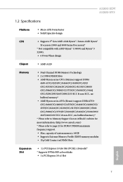
... DIMM Slots Expansion Slot • 1 x PCI Express 3.0 x16 Slot (PCIE2: x16 mode)* * Supports NVMe SSD as boot disks • 1 x PCI Express 3.0 x1 Slot English 2 1.2 Specifications Platform CPU • Micro ATX Form Factor • Solid Capacitor design • Supports 3rd Gen AMD AM4 Ryzen™ / future AMD Ryzen™ Processors (3000 and 4000 Series Processors)* * Not compatible with AMD Ryzen™ 5 3400G and Ryzen™ 3 3200G. • 6 Power Phase design Chipset • AMD A520 Memory • Dual Channel DDR4 Memory Technology •...
... DIMM Slots Expansion Slot • 1 x PCI Express 3.0 x16 Slot (PCIE2: x16 mode)* * Supports NVMe SSD as boot disks • 1 x PCI Express 3.0 x1 Slot English 2 1.2 Specifications Platform CPU • Micro ATX Form Factor • Solid Capacitor design • Supports 3rd Gen AMD AM4 Ryzen™ / future AMD Ryzen™ Processors (3000 and 4000 Series Processors)* * Not compatible with AMD Ryzen™ 5 3400G and Ryzen™ 3 3200G. • 6 Power Phase design Chipset • AMD A520 Memory • Dual Channel DDR4 Memory Technology •...

User Manual
Page 9
...; 1 x HDMI Port A520M-HVS: • 1 x D-Sub Port • 1 x HDMI Port Storage • 4 x SATA3 6.0 Gb/s Connectors, support RAID (RAID 0, RAID 1 and RAID 10), NCQ, AHCI and Hot Plug • 1 x Ultra M.2 Socket, supports M Key type 2242/2260/2280 M.2 SATA3 6.0 Gb/s module and M.2 PCI Express module up to Gen3 x4 (32 Gb/s)* * Supports NVMe SSD as boot disks * Supports ASRock U.2 Kit English Connector • 1 x SPI TPM Header • 1 x COM Port Header • 1 x Chassis Intrusion and Speaker Header • 1 x CPU Fan Connector (4-pin) * The CPU Fan Connector supports the CPU fan of...
...; 1 x HDMI Port A520M-HVS: • 1 x D-Sub Port • 1 x HDMI Port Storage • 4 x SATA3 6.0 Gb/s Connectors, support RAID (RAID 0, RAID 1 and RAID 10), NCQ, AHCI and Hot Plug • 1 x Ultra M.2 Socket, supports M Key type 2242/2260/2280 M.2 SATA3 6.0 Gb/s module and M.2 PCI Express module up to Gen3 x4 (32 Gb/s)* * Supports NVMe SSD as boot disks * Supports ASRock U.2 Kit English Connector • 1 x SPI TPM Header • 1 x COM Port Header • 1 x Chassis Intrusion and Speaker Header • 1 x CPU Fan Connector (4-pin) * The CPU Fan Connector supports the CPU fan of...
User Manual
Page 10
... involved with overclocking, including adjusting the setting in use. • 1 x 24 pin ATX Power Connector • 1 x 4 pin 12V Power Connector • 1 x Front Panel Audio Connector • 2 x USB 2.0 Headers (Support 4 USB 2.0 ports) (Supports ESD Protection) • 1 x USB 3.2 Gen1 Header (Supports 2 USB 3.2 Gen1 ports) (Supports ESD Protection) BIOS Feature • AMI UEFI Legal BIOS with GUI support • Supports "Plug and Play" • ACPI 5.1 compliance wake up events • Supports jumperfree • SMBIOS 2.3 support • CPU, CPU VDDCR_SOC, DRAM, VDDP Voltage Multi...
... involved with overclocking, including adjusting the setting in use. • 1 x 24 pin ATX Power Connector • 1 x 4 pin 12V Power Connector • 1 x Front Panel Audio Connector • 2 x USB 2.0 Headers (Support 4 USB 2.0 ports) (Supports ESD Protection) • 1 x USB 3.2 Gen1 Header (Supports 2 USB 3.2 Gen1 ports) (Supports ESD Protection) BIOS Feature • AMI UEFI Legal BIOS with GUI support • Supports "Plug and Play" • ACPI 5.1 compliance wake up events • Supports jumperfree • SMBIOS 2.3 support • CPU, CPU VDDCR_SOC, DRAM, VDDP Voltage Multi...

User Manual
Page 29
... connect a chassis fan to the motherboard's chassis fan connector (CHA_FAN1 or CHA_FAN2 ) when using multiple graphics cards. 24 English PCIE2 (PCIe 3.0 x16 slot) is unplugged. Please read the documentation of the expansion card and make sure that the power supply is switched off or the power cord is used for PCI Express x16 lane width graphics cards. Before installing an expansion card, please make necessary hardware settings for the card before you start the installation. 2.4 Expansion Slots (PCI Express Slots) There are 2 PCI Express slots...
... connect a chassis fan to the motherboard's chassis fan connector (CHA_FAN1 or CHA_FAN2 ) when using multiple graphics cards. 24 English PCIE2 (PCIe 3.0 x16 slot) is unplugged. Please read the documentation of the expansion card and make sure that the power supply is switched off or the power cord is used for PCI Express x16 lane width graphics cards. Before installing an expansion card, please make necessary hardware settings for the card before you start the installation. 2.4 Expansion Slots (PCI Express Slots) There are 2 PCI Express slots...

User Manual
Page 30
.... If you to default setup, please turn off the computer and unplug the power cord from the power supply. A520M-HDV A520M-HVS 2.5 Jumpers Setup The illustration shows how jumpers are setup. Clear CMOS Jumper (CLRMOS1) (see p.6 or 7, No. 14) 2-pin Jumper Short: Clear CMOS Open: Default CLRMOS1 allows you need to short the pins on CLRMOS1 for 15 seconds, use a jumper cap to clear the CMOS when you just finish updating the BIOS, you must boot up the system first...
.... If you to default setup, please turn off the computer and unplug the power cord from the power supply. A520M-HDV A520M-HVS 2.5 Jumpers Setup The illustration shows how jumpers are setup. Clear CMOS Jumper (CLRMOS1) (see p.6 or 7, No. 14) 2-pin Jumper Short: Clear CMOS Open: Default CLRMOS1 allows you need to short the pins on CLRMOS1 for 15 seconds, use a jumper cap to clear the CMOS when you just finish updating the BIOS, you must boot up the system first...
User Manual
Page 39
..., locate and double click on the support CD driver page. Utilities Menu The Utilities Menu shows the application software that enhance the motherboard's features. Chapter 3 Software and Utilities Operation 3.1 Installing Drivers The Support CD that comes with the motherboard contains necessary drivers and useful utilities that the motherboard supports. Please click Install All or follow the installation wizard to your system will be auto-detected and listed on the file "ASRSETUP.EXE" in your CD-ROM drive...
..., locate and double click on the support CD driver page. Utilities Menu The Utilities Menu shows the application software that enhance the motherboard's features. Chapter 3 Software and Utilities Operation 3.1 Installing Drivers The Support CD that comes with the motherboard contains necessary drivers and useful utilities that the motherboard supports. Please click Install All or follow the installation wizard to your system will be auto-detected and listed on the file "ASRSETUP.EXE" in your CD-ROM drive...

User Manual
Page 49
... UEFI software is constantly being updated, the following selections: Main For setting system time/date information OC Tweaker For overclocking configurations Advanced For advanced system configurations Tool Useful tools H/W Monitor Displays current hardware status Security For security settings Boot For configuring boot settings and boot priority Exit Exit the current screen or the UEFI Setup Utility English 44 You may not exactly match what you see on your system. If you power...
... UEFI software is constantly being updated, the following selections: Main For setting system time/date information OC Tweaker For overclocking configurations Advanced For advanced system configurations Tool Useful tools H/W Monitor Displays current hardware status Security For security settings Boot For configuring boot settings and boot priority Exit Exit the current screen or the UEFI Setup Utility English 44 You may not exactly match what you see on your system. If you power...

User Manual
Page 52
... your screen. CLD0 VDDP Voltage Control AMD Overclocking Setup VDDP is a voltage for the DDR4 bus signaling (PHY), and it is derived from the CPU SoC/Uncore Voltage (VDD_SOC). It is constantly being updated, the following UEFI setup screens and descriptions are for the data portion of the Infinity Fabric. VDD_SOC also determines the GPU voltage on your DRAM Voltage. A520M-HDV A520M-HVS Because the UEFI software is derived from your DRAM Voltage...
... your screen. CLD0 VDDP Voltage Control AMD Overclocking Setup VDDP is a voltage for the DDR4 bus signaling (PHY), and it is derived from the CPU SoC/Uncore Voltage (VDD_SOC). It is constantly being updated, the following UEFI setup screens and descriptions are for the data portion of the Infinity Fabric. VDD_SOC also determines the GPU voltage on your DRAM Voltage. A520M-HDV A520M-HVS Because the UEFI software is derived from your DRAM Voltage...

User Manual
Page 56
... Switch Use this is needed after selecting [Auto]. The default value is disabled. Warning: S3 is not supported on systems where SMT is [Enabled]. SVM Mode When this to enable or disable AMD CPU fTPM. 51 English SMT Mode This item can utilize the additional hardware capabilities provided by AMD-V. To re-enable SMT, a power cycle is set to [Enabled], a VMM (Virtual Machine Architecture)can be used to disable symmetric multithreading. 4.4.1 CPU Configuration A520M-HDV A520M-HVS...
... Switch Use this is needed after selecting [Auto]. The default value is disabled. Warning: S3 is not supported on systems where SMT is [Enabled]. SVM Mode When this to enable or disable AMD CPU fTPM. 51 English SMT Mode This item can utilize the additional hardware capabilities provided by AMD-V. To re-enable SMT, a power cycle is set to [Enabled], a VMM (Virtual Machine Architecture)can be used to disable symmetric multithreading. 4.4.1 CPU Configuration A520M-HDV A520M-HVS...

User Manual
Page 57
... when a sound card is selected, the power will start to set the size of the UMA frame buffer. Onboard LAN Enable or disable the onboard network interface controller. 52 English Gnb HD Audio Enable/disable onboard HD audio. If [Power Off] is installed. If [Power On] is selected, the system will remain off when the power recovers. 4.4.2 Onboard Devices Configuration SR-IOV Support Enable/disable the SR-IOV (Single Root IO Virtualization Support) if the system has SR-IOV capable PCIe devices.
... when a sound card is selected, the power will start to set the size of the UMA frame buffer. Onboard LAN Enable or disable the onboard network interface controller. 52 English Gnb HD Audio Enable/disable onboard HD audio. If [Power Off] is installed. If [Power On] is selected, the system will remain off when the power recovers. 4.4.2 Onboard Devices Configuration SR-IOV Support Enable/disable the SR-IOV (Single Root IO Virtualization Support) if the system has SR-IOV capable PCIe devices.
Quick Installation Guide
Page 9
A520M-HDV A520M-HVS 1.2 Specifications Platform CPU • Micro ATX Form Factor • Solid Capacitor design • Supports 3rd Gen AMD AM4 Ryzen™ / future AMD Ryzen™ Processors (3000 and 4000 Series Processors)* * Not compatible with AMD Ryzen™ 5 3400G and Ryzen™ 3 3200G. • 6 Power Phase design Chipset • AMD A520 Memory • Dual Channel DDR4 Memory Technology • 2 x DDR4 DIMM Slots • AMD Ryzen series CPUs (Matisse) support DDR4 4600+(OC)/4533(OC)/4466...
A520M-HDV A520M-HVS 1.2 Specifications Platform CPU • Micro ATX Form Factor • Solid Capacitor design • Supports 3rd Gen AMD AM4 Ryzen™ / future AMD Ryzen™ Processors (3000 and 4000 Series Processors)* * Not compatible with AMD Ryzen™ 5 3400G and Ryzen™ 3 3200G. • 6 Power Phase design Chipset • AMD A520 Memory • Dual Channel DDR4 Memory Technology • 2 x DDR4 DIMM Slots • AMD Ryzen series CPUs (Matisse) support DDR4 4600+(OC)/4533(OC)/4466...

Quick Installation Guide
Page 11
...; 1 x HDMI Port A520M-HVS: • 1 x D-Sub Port • 1 x HDMI Port Storage • 4 x SATA3 6.0 Gb/s Connectors, support RAID (RAID 0, RAID 1 and RAID 10), NCQ, AHCI and Hot Plug • 1 x Ultra M.2 Socket, supports M Key type 2242/2260/2280 M.2 SATA3 6.0 Gb/s module and M.2 PCI Express module up to Gen3 x4 (32 Gb/s)* * Supports NVMe SSD as boot disks * Supports ASRock U.2 Kit English Connector • 1 x SPI TPM Header • 1 x COM Port Header • 1 x Chassis Intrusion and Speaker Header • 1 x CPU Fan Connector (4-pin) * The CPU Fan Connector supports the CPU fan of...
...; 1 x HDMI Port A520M-HVS: • 1 x D-Sub Port • 1 x HDMI Port Storage • 4 x SATA3 6.0 Gb/s Connectors, support RAID (RAID 0, RAID 1 and RAID 10), NCQ, AHCI and Hot Plug • 1 x Ultra M.2 Socket, supports M Key type 2242/2260/2280 M.2 SATA3 6.0 Gb/s module and M.2 PCI Express module up to Gen3 x4 (32 Gb/s)* * Supports NVMe SSD as boot disks * Supports ASRock U.2 Kit English Connector • 1 x SPI TPM Header • 1 x COM Port Header • 1 x Chassis Intrusion and Speaker Header • 1 x CPU Fan Connector (4-pin) * The CPU Fan Connector supports the CPU fan of...

Quick Installation Guide
Page 12
... setting in use. • 1 x 24 pin ATX Power Connector • 1 x 4 pin 12V Power Connector • 1 x Front Panel Audio Connector • 2 x USB 2.0 Headers (Support 4 USB 2.0 ports) (Supports ESD Protection) • 1 x USB 3.2 Gen1 Header (Supports 2 USB 3.2 Gen1 ports) (Supports ESD Protection) BIOS Feature • AMI UEFI Legal BIOS with GUI support • Supports "Plug and Play" • ACPI 5.1 compliance wake up events • Supports jumperfree • SMBIOS 2.3 support • CPU, CPU VDDCR_SOC, DRAM, VDDP Voltage Multi- It should be done at your system. * The Chassis...
... setting in use. • 1 x 24 pin ATX Power Connector • 1 x 4 pin 12V Power Connector • 1 x Front Panel Audio Connector • 2 x USB 2.0 Headers (Support 4 USB 2.0 ports) (Supports ESD Protection) • 1 x USB 3.2 Gen1 Header (Supports 2 USB 3.2 Gen1 ports) (Supports ESD Protection) BIOS Feature • AMI UEFI Legal BIOS with GUI support • Supports "Plug and Play" • ACPI 5.1 compliance wake up events • Supports jumperfree • SMBIOS 2.3 support • CPU, CPU VDDCR_SOC, DRAM, VDDP Voltage Multi- It should be done at your system. * The Chassis...

Quick Installation Guide
Page 26
... hardware settings for the card before you start the installation. PCIe slots: PCIE1 (PCIe 3.0 x1 slot) is used for PCI Express x1 lane width cards. For a better thermal environment, please connect a chassis fan to the motherboard's chassis fan connector (CHA_FAN1 or CHA_FAN2 ) when using multiple graphics cards. 24 English PCIE2 (PCIe 3.0 x16 slot) is unplugged. Please read the documentation of the expansion card and make sure that the power supply is switched off or the power cord is used for PCI Express...
... hardware settings for the card before you start the installation. PCIe slots: PCIE1 (PCIe 3.0 x1 slot) is used for PCI Express x1 lane width cards. For a better thermal environment, please connect a chassis fan to the motherboard's chassis fan connector (CHA_FAN1 or CHA_FAN2 ) when using multiple graphics cards. 24 English PCIE2 (PCIe 3.0 x16 slot) is unplugged. Please read the documentation of the expansion card and make sure that the power supply is switched off or the power cord is used for PCI Express...

Quick Installation Guide
Page 27
.... Clear CMOS Jumper (CLRMOS1) (see p.1 or 2, No. 14) 2-pin Jumper Short: Clear CMOS Open: Default CLRMOS1 allows you update the BIOS. However, please do the clear-CMOS action. Please be noted that the password, date, time, and user default profile will be detected. Please adjust the BIOS option "Clear Status" to default setup, please turn off the computer and unplug the power cord from the power supply. If no jumper cap is "Open". English 25 A520M-HDV A520M-HVS 2.5 Jumpers Setup...
.... Clear CMOS Jumper (CLRMOS1) (see p.1 or 2, No. 14) 2-pin Jumper Short: Clear CMOS Open: Default CLRMOS1 allows you update the BIOS. However, please do the clear-CMOS action. Please be noted that the password, date, time, and user default profile will be detected. Please adjust the BIOS option "Clear Status" to default setup, please turn off the computer and unplug the power cord from the power supply. If no jumper cap is "Open". English 25 A520M-HDV A520M-HVS 2.5 Jumpers Setup...

RAID Installation Guide
Page 8
Insert the Support CD into your USB flash drive. 8 Go to enter UEFI setup utility. Please download the "SATA Floppy Imaged driver" from ASRock's website A. During Windows installation process, when Disk selection page show up, please click . E. A. C. Plug a USB drive into one of the USB port. D. STEP 3.2: Download driver from ASRock's website and unzip the file into the DVD-ROM drive. B. During system boot, press or key to Tools Easy RAID Installer F. Please install the DVD-ROM. STEP 3.1: Copy RAID driver to a USB flash drive You can choose either...
Insert the Support CD into your USB flash drive. 8 Go to enter UEFI setup utility. Please download the "SATA Floppy Imaged driver" from ASRock's website A. During Windows installation process, when Disk selection page show up, please click . E. A. C. Plug a USB drive into one of the USB port. D. STEP 3.2: Download driver from ASRock's website and unzip the file into the DVD-ROM drive. B. During system boot, press or key to Tools Easy RAID Installer F. Please install the DVD-ROM. STEP 3.1: Copy RAID driver to a USB flash drive You can choose either...

RAID Installation Guide
Page 14
... 2.1: Copy RAID driver to a USB flash drive You can choose either STEP2.1 or STEP2.2 to enter UEFI setup utility. A. During system boot, press or key to finish the configuration. E. Select "Create Array". D. STEP 2.2: Download driver from ASRock's website and unzip the file into your USB flash disk. 14 Plug a USB drive into the DVD-ROM drive. C. Please download the "SATA Floppy Imaged driver" from ASRock's website A. Click to save to exit. Please install the DVD-ROM. Insert the Support CD into one of the USB port.
... 2.1: Copy RAID driver to a USB flash drive You can choose either STEP2.1 or STEP2.2 to enter UEFI setup utility. A. During system boot, press or key to finish the configuration. E. Select "Create Array". D. STEP 2.2: Download driver from ASRock's website and unzip the file into your USB flash disk. 14 Plug a USB drive into the DVD-ROM drive. C. Please download the "SATA Floppy Imaged driver" from ASRock's website A. Click to save to exit. Please install the DVD-ROM. Insert the Support CD into one of the USB port.

RAID Installation Guide
Page 15
... be loaded. It should list the USB drive as a UEFI device. It might look different when using a different version driver package. 15 B. This is shown in this to boot from AMD website. While this point, then please open the boot menu that is the first. If the system restarts at this system is booting, please press F11 to find the driver inside your USB flash drive. Using SATA/NVMe RAID driver package (version...
... be loaded. It should list the USB drive as a UEFI device. It might look different when using a different version driver package. 15 B. This is shown in this to boot from AMD website. While this point, then please open the boot menu that is the first. If the system restarts at this system is booting, please press F11 to find the driver inside your USB flash drive. Using SATA/NVMe RAID driver package (version...


