
RAID Installation Guide
Page 2
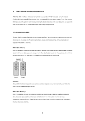
... RAID 0 function can start to use the onboard RAID Option ROM Utility to configure RAID. 1.1 Introduction to RAID The term "RAID" stands for you to the entire system since it will double the data transfer rate of a single disk alone while the two hard disks perform the same work as it does not provide any HDDs of the data in parallel, interleaved stacks. Hot-Plug any fault tolerance. 1. AMD BIOS RAID Installation Guide AMD BIOS RAID Installation Guide...
... RAID 0 function can start to use the onboard RAID Option ROM Utility to configure RAID. 1.1 Introduction to RAID The term "RAID" stands for you to the entire system since it will double the data transfer rate of a single disk alone while the two hard disks perform the same work as it does not provide any HDDs of the data in parallel, interleaved stacks. Hot-Plug any fault tolerance. 1. AMD BIOS RAID Installation Guide AMD BIOS RAID Installation Guide...
RAID Installation Guide
Page 8
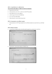
... install the DVD-ROM. B. During system boot, press or key to finish the driver copy process. Plug a USB drive into the DVD-ROM drive. D. Insert the Support CD into one of the USB port. Please download the "SATA Floppy Imaged driver" from ASRock's website A. STEP 3.2: Download driver from ASRock's website and unzip the file into your USB flash drive. 8 E. Follow instructions to enter UEFI setup utility. STEP 3.1: Copy RAID driver to a USB flash drive You can choose either STEP 3.1 or STEP 3.2 to Tools Easy RAID Installer F. During Windows installation...
... install the DVD-ROM. B. During system boot, press or key to finish the driver copy process. Plug a USB drive into the DVD-ROM drive. D. Insert the Support CD into one of the USB port. Please download the "SATA Floppy Imaged driver" from ASRock's website A. STEP 3.2: Download driver from ASRock's website and unzip the file into your USB flash drive. 8 E. Follow instructions to enter UEFI setup utility. STEP 3.1: Copy RAID driver to a USB flash drive You can choose either STEP 3.1 or STEP 3.2 to Tools Easy RAID Installer F. During Windows installation...
RAID Installation Guide
Page 12
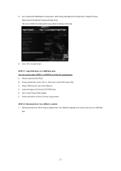
...; Easy RAID Installer F. C. Plug a USB drive into the DVD-ROM drive. Go to exit. STEP 2.1: Copy RAID driver to a USB flash drive You can choose either STEP2.1 or STEP2.2 to enter UEFI setup utility. Please install the DVD-ROM. E. H. Please download the "SATA Floppy Imaged driver" from ASRock's website A. B. During system boot, press or key to finish the configuration. Insert the Support CD into one of the USB port. D. Follow instructions to delete the existing disk arrays before creating a new array. STEP 2.2: Download driver from ASRock...
...; Easy RAID Installer F. C. Plug a USB drive into the DVD-ROM drive. Go to exit. STEP 2.1: Copy RAID driver to a USB flash drive You can choose either STEP2.1 or STEP2.2 to enter UEFI setup utility. Please install the DVD-ROM. E. H. Please download the "SATA Floppy Imaged driver" from ASRock's website A. B. During system boot, press or key to finish the configuration. Insert the Support CD into one of the USB port. D. Follow instructions to delete the existing disk arrays before creating a new array. STEP 2.2: Download driver from ASRock...
Quick Installation Guide
Page 5
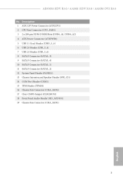
...-pin DDR4 DIMM Slots (DDR4_A1, DDR4_A2) 4 ATX Power Connector (ATXPWR1) 5 USB 3.1 Gen1 Header (USB3_5_6) 6 USB 2.0 Header (USB_3_4) 7 USB 2.0 Header (USB_5_6) 8 SATA3 Connector (SATA3_3) 9 SATA3 Connector (SATA3_4) 10 SATA3 Connector (SATA3_1) 11 SATA3 Connector (SATA3_2) 12 System Panel Header (PANEL1) 13 Chassis Intrusion and Speaker Header (SPK_CI1) 14 COM Port Header (COM1) 15 TPM Header (TPMS1) 16 Chassis Fan Connector (CHA_FAN2) 17 Clear CMOS Jumper (CLRCMOS1) 18 Front Panel Audio Header (HD_AUDIO1) 19 Chassis Fan Connector (CHA_FAN1) 3 English AB350M-HDV R3.0 / A320M-HDV R3.0 / A320M...
...-pin DDR4 DIMM Slots (DDR4_A1, DDR4_A2) 4 ATX Power Connector (ATXPWR1) 5 USB 3.1 Gen1 Header (USB3_5_6) 6 USB 2.0 Header (USB_3_4) 7 USB 2.0 Header (USB_5_6) 8 SATA3 Connector (SATA3_3) 9 SATA3 Connector (SATA3_4) 10 SATA3 Connector (SATA3_1) 11 SATA3 Connector (SATA3_2) 12 System Panel Header (PANEL1) 13 Chassis Intrusion and Speaker Header (SPK_CI1) 14 COM Port Header (COM1) 15 TPM Header (TPMS1) 16 Chassis Fan Connector (CHA_FAN2) 17 Clear CMOS Jumper (CLRCMOS1) 18 Front Panel Audio Header (HD_AUDIO1) 19 Chassis Fan Connector (CHA_FAN1) 3 English AB350M-HDV R3.0 / A320M-HDV R3.0 / A320M...
Quick Installation Guide
Page 9
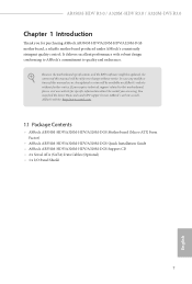
... VGA cards and CPU support list on ASRock's website without notice. Because the motherboard specifications and the BIOS software might be updated, the content of this manual occur, the updated version will be available on ASRock's website as well. ASRock website http://www.asrock.com. 1.1 Package Contents • ASRock AB350M-HDV/A320M-HDV/A320M-DGS Motherboard (Micro ATX Form Factor) • ASRock AB350M-HDV/A320M-HDV/A320M-DGS Quick Installation Guide • ASRock AB350M-HDV/A320M-HDV/A320M-DGS Support CD • 2 x Serial ATA (SATA) Data Cables (Optional) • 1 x I/O Panel...
... VGA cards and CPU support list on ASRock's website without notice. Because the motherboard specifications and the BIOS software might be updated, the content of this manual occur, the updated version will be available on ASRock's website as well. ASRock website http://www.asrock.com. 1.1 Package Contents • ASRock AB350M-HDV/A320M-HDV/A320M-DGS Motherboard (Micro ATX Form Factor) • ASRock AB350M-HDV/A320M-HDV/A320M-DGS Quick Installation Guide • ASRock AB350M-HDV/A320M-HDV/A320M-DGS Support CD • 2 x Serial ATA (SATA) Data Cables (Optional) • 1 x I/O Panel...
Quick Installation Guide
Page 10
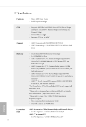
...; 1 x PCI Express 3.0 x16 Slot (PCIE2: x16 mode)* AMD 7th A-Series APUs • 1 x PCI Express 3.0 x16 Slot (PCIE2: x8 mode)* 8 1.2 Specifications Platform • Micro ATX Form Factor • Solid Capacitor design CPU • Supports AMD Socket AM4 A-Series APUs (Bristol Ridge) and Ryzen Series CPUs (Summit Ridge, Raven Ridge and Pinnacle Ridge) • 6 Power Phase design • Supports CPU up to 105W Chipset • AMD Promontory B350 (AB350M-HDV R3.0) • AMD Promontory A320 (A320M-HDV R3.0 / A320M-DVS R3.0) Memory • Dual Channel DDR4 Memory Technology...
...; 1 x PCI Express 3.0 x16 Slot (PCIE2: x16 mode)* AMD 7th A-Series APUs • 1 x PCI Express 3.0 x16 Slot (PCIE2: x8 mode)* 8 1.2 Specifications Platform • Micro ATX Form Factor • Solid Capacitor design CPU • Supports AMD Socket AM4 A-Series APUs (Bristol Ridge) and Ryzen Series CPUs (Summit Ridge, Raven Ridge and Pinnacle Ridge) • 6 Power Phase design • Supports CPU up to 105W Chipset • AMD Promontory B350 (AB350M-HDV R3.0) • AMD Promontory A320 (A320M-HDV R3.0 / A320M-DVS R3.0) Memory • Dual Channel DDR4 Memory Technology...
Quick Installation Guide
Page 12
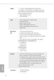
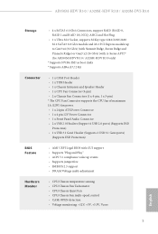
...x PS/2 Mouse/Keyboard Port • 2 x USB 2.0 Ports (Supports ESD Protection) • 4 x USB 3.1 Gen1 Ports (Supports ESD Protection) • 1 x RJ-45 LAN Port with LED (ACT/LINK LED and SPEED LED) • HD Audio Jacks: Line in / Front Speaker / Microphone AB350M-HDV R3.0 / A320M-HDV R3.0: • 1 x D-Sub Port • 1 x DVI-D Port • 1 x HDMI Port A320M-DVS R3.0: • 1 x D-Sub Port • 1 x DVI-D Port Storage • 4 x SATA3 6.0 Gb/s Connectors, support RAID (RAID 0, RAID 1 and RAID 10), NCQ, AHCI and Hot Plug • 1 x Ultra M.2 Socket, supports M Key type 2242/2260...
...x PS/2 Mouse/Keyboard Port • 2 x USB 2.0 Ports (Supports ESD Protection) • 4 x USB 3.1 Gen1 Ports (Supports ESD Protection) • 1 x RJ-45 LAN Port with LED (ACT/LINK LED and SPEED LED) • HD Audio Jacks: Line in / Front Speaker / Microphone AB350M-HDV R3.0 / A320M-HDV R3.0: • 1 x D-Sub Port • 1 x DVI-D Port • 1 x HDMI Port A320M-DVS R3.0: • 1 x D-Sub Port • 1 x DVI-D Port Storage • 4 x SATA3 6.0 Gb/s Connectors, support RAID (RAID 0, RAID 1 and RAID 10), NCQ, AHCI and Hot Plug • 1 x Ultra M.2 Socket, supports M Key type 2242/2260...
Quick Installation Guide
Page 13
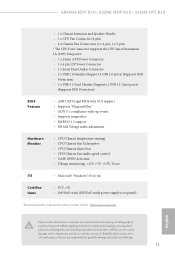
...devices of maximum 1A (12W) fan power. • 1 x 24 pin ATX Power Connector • 1 x 4 pin 12V Power Connector • 1 x Front Panel Audio Connector • 2 x USB 2.0 Headers (Support 4 USB 2.0 ports) (Supports ESD Protection) • 1 x USB 3.1 Gen1 Header (Supports 2 USB 3.1 Gen1 ports) (Supports ESD Protection) • AMI UEFI Legal BIOS with GUI support • Supports "Plug and Play" • ACPI 5.1 compliance wake up events • Supports jumperfree • SMBIOS 2.3 support • DRAM Voltage multi-adjustment • CPU/Chassis temperature sensing • CPU/Chassis...
...devices of maximum 1A (12W) fan power. • 1 x 24 pin ATX Power Connector • 1 x 4 pin 12V Power Connector • 1 x Front Panel Audio Connector • 2 x USB 2.0 Headers (Support 4 USB 2.0 ports) (Supports ESD Protection) • 1 x USB 3.1 Gen1 Header (Supports 2 USB 3.1 Gen1 ports) (Supports ESD Protection) • AMI UEFI Legal BIOS with GUI support • Supports "Plug and Play" • ACPI 5.1 compliance wake up events • Supports jumperfree • SMBIOS 2.3 support • DRAM Voltage multi-adjustment • CPU/Chassis temperature sensing • CPU/Chassis...
Quick Installation Guide
Page 19
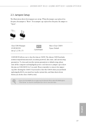
... BIOS option "Clear Status" to clear the CMOS when you just finish updating the BIOS, you must boot up the system first, and then shut it down before you need to clear the record of previous chassis intrusion status. Clear CMOS Jumper (CLRCMOS1) (see p.1, 2, No. 17) 2-pin Jumper Short: Clear CMOS Open: Default CLRCMOS1 allows you clear the CMOS, the case open may be detected. To clear and reset the system parameters to default setup, please turn...
... BIOS option "Clear Status" to clear the CMOS when you just finish updating the BIOS, you must boot up the system first, and then shut it down before you need to clear the record of previous chassis intrusion status. Clear CMOS Jumper (CLRCMOS1) (see p.1, 2, No. 17) 2-pin Jumper Short: Clear CMOS Open: Default CLRCMOS1 allows you clear the CMOS, the case open may be detected. To clear and reset the system parameters to default setup, please turn...
User Manual
Page 4
... 1 1.2 Specifications 2 1.3 Motherboard Layout 7 1.4 I/O Panel 10 Chapter 2 Installation 13 2.1 Installing the CPU 14 2.2 Installing the CPU Fan and Heatsink 16 2.3 Installing Memory Modules (DIMM) 24 2.4 Expansion Slots (PCI Express Slots) 27 2.5 Jumpers Setup 28 2.6 Onboard Headers and Connectors 29 2.7 M.2_SSD (NGFF) Module Installation Guide (for AB350M-HDV R3.0 / A320M-HDV R3.0 only) 33 Chapter 3 Software and Utilities Operation 37 3.1 Installing Drivers 37 3.2 A-Tuning 38 3.2.1 Installing A-Tuning 38 3.2.2 Using A-Tuning 38 3.3 ASRock Live Update & APP...
... 1 1.2 Specifications 2 1.3 Motherboard Layout 7 1.4 I/O Panel 10 Chapter 2 Installation 13 2.1 Installing the CPU 14 2.2 Installing the CPU Fan and Heatsink 16 2.3 Installing Memory Modules (DIMM) 24 2.4 Expansion Slots (PCI Express Slots) 27 2.5 Jumpers Setup 28 2.6 Onboard Headers and Connectors 29 2.7 M.2_SSD (NGFF) Module Installation Guide (for AB350M-HDV R3.0 / A320M-HDV R3.0 only) 33 Chapter 3 Software and Utilities Operation 37 3.1 Installing Drivers 37 3.2 A-Tuning 38 3.2.1 Installing A-Tuning 38 3.2.2 Using A-Tuning 38 3.3 ASRock Live Update & APP...
User Manual
Page 6
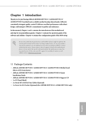
... / A320M-DVS R3.0 Support CD • 1 x I/O Panel Shield • 2 x Serial ATA (SATA) Data Cables (Optional) • 1 x Screw for M.2 Socket (Optional) (for purchasing ASRock AB350M-HDV R3.0 / A320M-HDV R3.0 / A320M-DVS R3.0 motherboard, a reliable motherboard produced under ASRock's consistently stringent quality control. Chapter 3 contains the operation guide of the BIOS setup. If you require technical support related to quality and endurance. Chapter 4 contains the configuration guide of the software and utilities. In case any modifications of this manual will be updated...
... / A320M-DVS R3.0 Support CD • 1 x I/O Panel Shield • 2 x Serial ATA (SATA) Data Cables (Optional) • 1 x Screw for M.2 Socket (Optional) (for purchasing ASRock AB350M-HDV R3.0 / A320M-HDV R3.0 / A320M-DVS R3.0 motherboard, a reliable motherboard produced under ASRock's consistently stringent quality control. Chapter 3 contains the operation guide of the BIOS setup. If you require technical support related to quality and endurance. Chapter 4 contains the configuration guide of the software and utilities. In case any modifications of this manual will be updated...
User Manual
Page 10
... x 24 pin ATX Power Connector • 1 x 4 pin 12V Power Connector • 1 x Front Panel Audio Connector • 2 x USB 2.0 Headers (Support 4 USB 2.0 ports) (Supports ESD Protection) • 1 x USB 3.1 Gen1 Header (Supports 2 USB 3.1 Gen1 ports) (Supports ESD Protection) BIOS Feature • AMI UEFI Legal BIOS with GUI support • Supports "Plug and Play" • ACPI 5.1 compliance wake up events • Supports jumperfree • SMBIOS 2.3 support • DRAM Voltage multi-adjustment Hardware Monitor • CPU/Chassis temperature sensing • CPU/Chassis Fan Tachometer...
... x 24 pin ATX Power Connector • 1 x 4 pin 12V Power Connector • 1 x Front Panel Audio Connector • 2 x USB 2.0 Headers (Support 4 USB 2.0 ports) (Supports ESD Protection) • 1 x USB 3.1 Gen1 Header (Supports 2 USB 3.1 Gen1 ports) (Supports ESD Protection) BIOS Feature • AMI UEFI Legal BIOS with GUI support • Supports "Plug and Play" • ACPI 5.1 compliance wake up events • Supports jumperfree • SMBIOS 2.3 support • DRAM Voltage multi-adjustment Hardware Monitor • CPU/Chassis temperature sensing • CPU/Chassis Fan Tachometer...

User Manual
Page 14
...A320M-DVS R3.0 No. Description 1 ATX 12V Power Connector (ATX12V1) 2 CPU Fan Connector (CPU_FAN1) 3 2 x 288-pin DDR4 DIMM Slots (DDR4_A1, DDR4_A2) 4 ATX Power Connector (ATXPWR1) 5 USB 3.1 Gen1 Header (USB3_5_6) 6 USB 2.0 Header (USB_3_4) 7 USB 2.0 Header (USB_5_6) 8 SATA3 Connector (SATA3_3) 9 SATA3 Connector (SATA3_4) 10 SATA3 Connector (SATA3_1) 11 SATA3 Connector (SATA3_2) 12 System Panel Header (PANEL1) 13 Chassis Intrusion and Speaker Header (SPK_CI1) 14 COM Port Header (COM1) 15 TPM Header (TPMS1) 16 Chassis Fan Connector (CHA_FAN2) 17 Clear CMOS Jumper (CLRCMOS1) 18 Front Panel Audio...
...A320M-DVS R3.0 No. Description 1 ATX 12V Power Connector (ATX12V1) 2 CPU Fan Connector (CPU_FAN1) 3 2 x 288-pin DDR4 DIMM Slots (DDR4_A1, DDR4_A2) 4 ATX Power Connector (ATXPWR1) 5 USB 3.1 Gen1 Header (USB3_5_6) 6 USB 2.0 Header (USB_3_4) 7 USB 2.0 Header (USB_5_6) 8 SATA3 Connector (SATA3_3) 9 SATA3 Connector (SATA3_4) 10 SATA3 Connector (SATA3_1) 11 SATA3 Connector (SATA3_2) 12 System Panel Header (PANEL1) 13 Chassis Intrusion and Speaker Header (SPK_CI1) 14 COM Port Header (COM1) 15 TPM Header (TPMS1) 16 Chassis Fan Connector (CHA_FAN2) 17 Clear CMOS Jumper (CLRCMOS1) 18 Front Panel Audio...
User Manual
Page 42
... auto-detected and listed on a specific item then follow the order from top to bottom to display the menu. If the Main Menu does not appear automatically, locate and double click on the file "ASRSETUP.EXE" in your CD-ROM drive. AB350M-HDV R3.0 / A320M-HDV R3.0 / A320M-DVS R3.0 Chapter 3 Software and Utilities Operation 3.1 Installing Drivers The Support CD that comes with the motherboard contains necessary drivers and useful utilities that the motherboard supports. Therefore, the drivers you install can work...
... auto-detected and listed on a specific item then follow the order from top to bottom to display the menu. If the Main Menu does not appear automatically, locate and double click on the file "ASRSETUP.EXE" in your CD-ROM drive. AB350M-HDV R3.0 / A320M-HDV R3.0 / A320M-DVS R3.0 Chapter 3 Software and Utilities Operation 3.1 Installing Drivers The Support CD that comes with the motherboard contains necessary drivers and useful utilities that the motherboard supports. Therefore, the drivers you install can work...
User Manual
Page 62
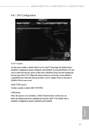
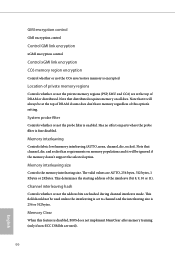
.... AB350M-HDV R3.0 / A320M-HDV R3.0 / A320M-DVS R3.0 4.4.1 CPU Configuration Cool 'n' Quiet Use this function may reduce CPU voltage and memory frequency, and lead to system stability or compatibility issue with some memory modules or power supplies. The default value is [Enabled]. Configuration options: [Enabled] and [Disabled]. 57 English The default value is [Enabled]. Configuration options: [Enabled] and [Disabled]. AMD fTPM Switch Use this option is set to enable or disable AMD CPU fTPM. SVM Mode When this to [Enabled], a VMM (Virtual Machine Architecture) can utilize the...
.... AB350M-HDV R3.0 / A320M-HDV R3.0 / A320M-DVS R3.0 4.4.1 CPU Configuration Cool 'n' Quiet Use this function may reduce CPU voltage and memory frequency, and lead to system stability or compatibility issue with some memory modules or power supplies. The default value is [Enabled]. Configuration options: [Enabled] and [Disabled]. 57 English The default value is [Enabled]. Configuration options: [Enabled] and [Disabled]. AMD fTPM Switch Use this option is set to enable or disable AMD CPU fTPM. SVM Mode When this to [Enabled], a VMM (Virtual Machine Architecture) can utilize the...
User Manual
Page 66
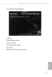
PS2 Y-Cable Enable the PS2 Y-Cable or set this option to Auto. 61 English AB350M-HDV R3.0 / A320M-HDV R3.0 / A320M-DVS R3.0 4.4.5 Super IO Configuration Serial Port Enable or disable the Serial port. Serial Port Address Select the address of the Serial port.
PS2 Y-Cable Enable the PS2 Y-Cable or set this option to Auto. 61 English AB350M-HDV R3.0 / A320M-HDV R3.0 / A320M-DVS R3.0 4.4.5 Super IO Configuration Serial Port Enable or disable the Serial port. Serial Port Address Select the address of the Serial port.
User Manual
Page 70
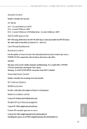
... scrubber control Control DF::RedirScrubCtrl[EnRedirScrub] Disable DF sync flood propagation Control DF::PIEConfig[DisSyncFloodProp]. AB350M-HDV R3.0 / A320M-HDV R3.0 / A320M-DVS R3.0 Opcache Control Enables or disables the Opcache. The valid values for future selections to scrub memory. Core/Thread Enablement Downcore control Sets the number of hours to take effect. To re-enable SMT, a POWER CYCLE is the number of cores to be used to remove any cores, a POWER CYCLE is disabled. DF Common Options DRAM...
... scrubber control Control DF::RedirScrubCtrl[EnRedirScrub] Disable DF sync flood propagation Control DF::PIEConfig[DisSyncFloodProp]. AB350M-HDV R3.0 / A320M-HDV R3.0 / A320M-DVS R3.0 Opcache Control Enables or disables the Opcache. The valid values for future selections to scrub memory. Core/Thread Enablement Downcore control Sets the number of hours to take effect. To re-enable SMT, a POWER CYCLE is the number of cores to be used to remove any cores, a POWER CYCLE is disabled. DF Common Options DRAM...
User Manual
Page 71
... Controls fabric level memory interleaving (AUTO, none, channel, die, socket). This determines the starting address of the interleave (bit 8, 9, 10 or 11). This field should not be ignored if the memory doesn't support the selected option. Note that it will always be at the top of DRAM or distributed. Memory Clear When this option's setting. Note that distributed requires memory on memory populations and it will be used...
... Controls fabric level memory interleaving (AUTO, none, channel, die, socket). This determines the starting address of the interleave (bit 8, 9, 10 or 11). This field should not be ignored if the memory doesn't support the selected option. Note that it will always be at the top of DRAM or distributed. Memory Clear When this option's setting. Note that distributed requires memory on memory populations and it will be used...
User Manual
Page 78
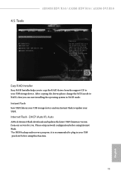
...), Auto ASRock Internet Flash downloads and updates the latest UEFI firmware version from the support CD to your USB pen drive before using this function. 73 English Please setup network configuration before using Internet Flash. *For BIOS backup and recovery purpose, it is recommended to plug in RAID mode. 4.5 Tools AB350M-HDV R3.0 / A320M-HDV R3.0 / A320M-DVS R3.0 Easy RAID Installer Easy RAID Installer helps you to copy the RAID driver from our servers for you can start installing the operating system in your USB storage device. Internet Flash - Instant Flash...
...), Auto ASRock Internet Flash downloads and updates the latest UEFI firmware version from the support CD to your USB pen drive before using this function. 73 English Please setup network configuration before using Internet Flash. *For BIOS backup and recovery purpose, it is recommended to plug in RAID mode. 4.5 Tools AB350M-HDV R3.0 / A320M-HDV R3.0 / A320M-DVS R3.0 Easy RAID Installer Easy RAID Installer helps you to copy the RAID driver from our servers for you can start installing the operating system in your USB storage device. Internet Flash - Instant Flash...
User Manual
Page 79
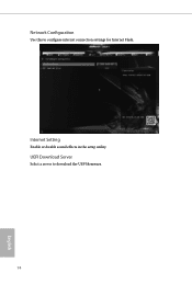
UEFI Download Server Select a server to configure internet connection settings for Internet Flash. Network Configuration Use this to download the UEFI firmware. 74 English Internet Setting Enable or disable sound effects in the setup utility.
UEFI Download Server Select a server to configure internet connection settings for Internet Flash. Network Configuration Use this to download the UEFI firmware. 74 English Internet Setting Enable or disable sound effects in the setup utility.


