User Manual
Page 7
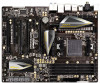
... EJ188H, support USB 1.1/2.0/3.0 up to -Use USB 3.0 Ports - 2 x eSATA3 Connectors - 1 x RJ-45 LAN Port with LED (ACT/LINK LED and SPEED LED) - 1 x IEEE 1394 Port - 1 x Clear CMOS Switch with LED - Intel® 82583V - Front panel audio connector - 2 x USB 2.0 headers (support 4 USB 2.0 ports) - 2 x USB 3.0 headers (support 4 USB 3.0 ports) 7 Supports PXE I /O SATA3 USB 3.0 Connector...
... EJ188H, support USB 1.1/2.0/3.0 up to -Use USB 3.0 Ports - 2 x eSATA3 Connectors - 1 x RJ-45 LAN Port with LED (ACT/LINK LED and SPEED LED) - 1 x IEEE 1394 Port - 1 x Clear CMOS Switch with LED - Intel® 82583V - Front panel audio connector - 2 x USB 2.0 headers (support 4 USB 2.0 ports) - 2 x USB 3.0 headers (support 4 USB 3.0 ports) 7 Supports PXE I /O SATA3 USB 3.0 Connector...
User Manual
Page 14
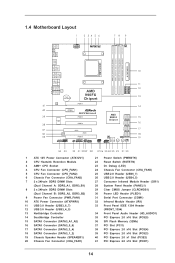
...B: USB3 Top: RJ-45 Top: SIDE SPK Center: REAR SPK Center: FRONT LAN Top: LINE IN AUDIO CODEC CMOS BATTERY AMD 990FX Chipset PCIE1 Super I/O PCIE2 990FX Extreme9 PCIE3 PCIE4 AMD SB950 Chipset SATA3_A1_A2 SATA3_5_6 SATA3_3_4 32Mb BIOS FRONT_1394 HD_AUDIO1 1 11 PCI1 RoHS IR1 1 1 PCIE5 COM1 PLED1...Module Header (CIR1) (Dual Channel A: DDR3_A1, DDR3_B1) 28 System Panel Header (PANEL1) 8 2 x 240-pin DDR3 DIMM Slots 29 Clear CMOS Jumper (CLRCMOS1) (Dual Channel B: DDR3_A2, DDR3_B2) 30 Power LED Header (PLED1) 9 Power Fan Connector (PWR_FAN1) 31 Serial Port Connector...
...B: USB3 Top: RJ-45 Top: SIDE SPK Center: REAR SPK Center: FRONT LAN Top: LINE IN AUDIO CODEC CMOS BATTERY AMD 990FX Chipset PCIE1 Super I/O PCIE2 990FX Extreme9 PCIE3 PCIE4 AMD SB950 Chipset SATA3_A1_A2 SATA3_5_6 SATA3_3_4 32Mb BIOS FRONT_1394 HD_AUDIO1 1 11 PCI1 RoHS IR1 1 1 PCIE5 COM1 PLED1...Module Header (CIR1) (Dual Channel A: DDR3_A1, DDR3_B1) 28 System Panel Header (PANEL1) 8 2 x 240-pin DDR3 DIMM Slots 29 Clear CMOS Jumper (CLRCMOS1) (Dual Channel B: DDR3_A2, DDR3_B2) 30 Power LED Header (PLED1) 9 Power Fan Connector (PWR_FAN1) 31 Serial Port Connector...

User Manual
Page 15
... 18 19 Microphone (Pink) USB 3.0 Ports (USB3_2_3) IEEE 1394 Port (IEEE 1394) eSATA3 Connector (ESATA1) eSATA3 Connector (ESATA2) USB 3.0 Ports (USB3_0_1) Optical SPDIF Out Port Clear CMOS Switch (CLRCBTN) PS/2 Keyboard Port (Purple) * There are two LED next to the table below for connection details in accordance with the type of speaker...
... 18 19 Microphone (Pink) USB 3.0 Ports (USB3_2_3) IEEE 1394 Port (IEEE 1394) eSATA3 Connector (ESATA1) eSATA3 Connector (ESATA2) USB 3.0 Ports (USB3_0_1) Optical SPDIF Out Port Clear CMOS Switch (CLRCBTN) PS/2 Keyboard Port (Purple) * There are two LED next to the table below for connection details in accordance with the type of speaker...
User Manual
Page 36
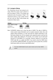
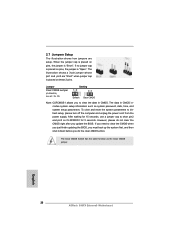
... pins. When the jumper cap is placed on pins, the jumper is "Short". Jumper Setting Clear CMOS Jumper (CLRCMOS1) (see p.14, No. 29) Default Clear CMOS Note: CLRCMOS1 allows you do not clear the CMOS right after you need to default setup, please turn off the computer and unplug the power cord ...shut it down before you to short pin2 and pin3 on CLRCMOS1 for 15 seconds, use a jumper cap to clear the data in CMOS includes system setup information such as the Clear CMOS jumper. 36 The illustration shows a 3-pin jumper whose pin1 and pin2 are setup. If you update the BIOS...
... pins. When the jumper cap is placed on pins, the jumper is "Short". Jumper Setting Clear CMOS Jumper (CLRCMOS1) (see p.14, No. 29) Default Clear CMOS Note: CLRCMOS1 allows you do not clear the CMOS right after you need to default setup, please turn off the computer and unplug the power cord ...shut it down before you to short pin2 and pin3 on CLRCMOS1 for 15 seconds, use a jumper cap to clear the data in CMOS includes system setup information such as the Clear CMOS jumper. 36 The illustration shows a 3-pin jumper whose pin1 and pin2 are setup. If you update the BIOS...

User Manual
Page 44
... switch, allowing users to quickly clear the CMOS values. 44 Clear CMOS Switch (CLRCBTN) (see p.14 No. 21) Power Power Switch is a smart switch, allowing users to quickly reset the system. Power Switch (PWRBTN) (see p.15 No. 18) clr CMOS Clear CMOS Switch is a smart switch, allowing... users to quickly turn on /off or reset the sytem clear the CMOS values. 2.11 Smart Switches The motherboard has three smart switches: power switch, reset...
... switch, allowing users to quickly clear the CMOS values. 44 Clear CMOS Switch (CLRCBTN) (see p.14 No. 21) Power Power Switch is a smart switch, allowing users to quickly reset the system. Power Switch (PWRBTN) (see p.15 No. 18) clr CMOS Clear CMOS Switch is a smart switch, allowing... users to quickly turn on /off or reset the sytem clear the CMOS values. 2.11 Smart Switches The motherboard has three smart switches: power switch, reset...

User Manual
Page 45
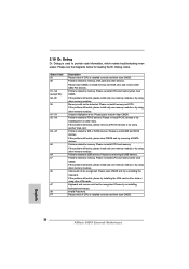
... install only one memory module or try removing all SATA devices. Memory could not be recognized. If the problem still exists, please clear CMOS and try installing the VGA card in other memory modules. Problem related to memory. If the problem still exists, please try removing ...all USB devices. Problem related to provide code information, which makes troubleshooting even easier. Please clear CMOS, re-install memory and VGA card, and remove other devices. If the problem still exists, please install only one memory module or ...
... install only one memory module or try removing all SATA devices. Memory could not be recognized. If the problem still exists, please clear CMOS and try installing the VGA card in other memory modules. Problem related to memory. If the problem still exists, please try removing ...all USB devices. Problem related to provide code information, which makes troubleshooting even easier. Please clear CMOS, re-install memory and VGA card, and remove other devices. If the problem still exists, please install only one memory module or ...
User Manual
Page 73
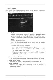
... This shows the number of these three options: [Disabled] - Boot From Onboard LAN Use this section, it will not be able to enter BIOS Setup (Clear CMOS or run utility in order to wait for you are using an USB flash drive. [Ultra Fast] - The only restriction is [Disabled]. Disable Fast Boot...
... This shows the number of these three options: [Disabled] - Boot From Onboard LAN Use this section, it will not be able to enter BIOS Setup (Clear CMOS or run utility in order to wait for you are using an USB flash drive. [Ultra Fast] - The only restriction is [Disabled]. Disable Fast Boot...

User Guide
Page 2
...) 24 Chassis Fan Connector (CHA_FAN3) 25 USB 2.0 Header (USB6_7) 26 USB 2.0 Header (USB4_5) 27 Consumer Infrared Module Header (CIR1) 28 System Panel Header (PANEL1) 29 Clear CMOS Jumper (CLRCMOS1) 30 Power LED Header (PLED1) 31 Serial Port Connector (COM1) 32 Infrared Module Header (IR1) 33 Front Panel IEEE 1394 Header (FRONT_1394) 34... (PCI1) 38 PCI Express 2.0 x16 Slot (PCIE4) 39 PCI Express 2.0 x16 Slot (PCIE3) 40 PCI Express 2.0 x1 Slot (PCIE2) 41 PCI Express 2.0 x16 Slot (PCIE1) 2 ASRock 990FX Extreme9 Motherboard English
...) 24 Chassis Fan Connector (CHA_FAN3) 25 USB 2.0 Header (USB6_7) 26 USB 2.0 Header (USB4_5) 27 Consumer Infrared Module Header (CIR1) 28 System Panel Header (PANEL1) 29 Clear CMOS Jumper (CLRCMOS1) 30 Power LED Header (PLED1) 31 Serial Port Connector (COM1) 32 Infrared Module Header (IR1) 33 Front Panel IEEE 1394 Header (FRONT_1394) 34... (PCI1) 38 PCI Express 2.0 x16 Slot (PCIE4) 39 PCI Express 2.0 x16 Slot (PCIE3) 40 PCI Express 2.0 x1 Slot (PCIE2) 41 PCI Express 2.0 x16 Slot (PCIE1) 2 ASRock 990FX Extreme9 Motherboard English

User Guide
Page 3
... Speaker Rear Speaker Central / Bass Side Speaker (No. 10) (No. 7) (No. 8) (No. 6) 2 V -- -- -- 4 V V -- -- 6 V V V -- 8 V V V V 3 ASRock 990FX Extreme9 Motherboard I/O Panel 1 2 3 45 69 7 10 8 11 19 18 17 16 15 14 13 12 1 2 3 4 * 5 6 7 8 9 ** 10 PS/2 Mouse Port (Green) Coaxial SPDIF Out Port USB...IEEE 1394 Port (IEEE 1394) eSATA3 Connector (ESATA1) eSATA3 Connector (ESATA2) USB 3.0 Ports (USB3_0_1) Optical SPDIF Out Port Clear CMOS Switch (CLRCBTN) PS/2 Keyboard Port (Purple) * There are two LED next to the table below for connection details in accordance...
... Speaker Rear Speaker Central / Bass Side Speaker (No. 10) (No. 7) (No. 8) (No. 6) 2 V -- -- -- 4 V V -- -- 6 V V V -- 8 V V V V 3 ASRock 990FX Extreme9 Motherboard I/O Panel 1 2 3 45 69 7 10 8 11 19 18 17 16 15 14 13 12 1 2 3 4 * 5 6 7 8 9 ** 10 PS/2 Mouse Port (Green) Coaxial SPDIF Out Port USB...IEEE 1394 Port (IEEE 1394) eSATA3 Connector (ESATA1) eSATA3 Connector (ESATA2) USB 3.0 Ports (USB3_0_1) Optical SPDIF Out Port Clear CMOS Switch (CLRCBTN) PS/2 Keyboard Port (Purple) * There are two LED next to the table below for connection details in accordance...
User Guide
Page 7
Supports Wake-On-LAN - Front panel audio connector - 2 x USB 2.0 headers (support 4 USB 2.0 ports) - 2 x USB 3.0 headers (support 4 USB 3.0 ports) 7 ASRock 990FX Extreme9 Motherboard English LAN Rear Panel I /O Panel - 1 x PS/2 Mouse Port - 1 x PS/2 Keyboard Port - 1 x Coaxial SPDIF Out Port - 1 x Optical SPDIF Out Port - 4 x Ready-to-Use USB 2.0 ... up to -Use USB 3.0 Ports - 2 x eSATA3 Connectors - 1 x RJ-45 LAN Port with LED (ACT/LINK LED and SPEED LED) - 1 x IEEE 1394 Port - 1 x Clear CMOS Switch with LED - Supports PXE I /O SATA3 USB 3.0 Connector - Intel® 82583V -
Supports Wake-On-LAN - Front panel audio connector - 2 x USB 2.0 headers (support 4 USB 2.0 ports) - 2 x USB 3.0 headers (support 4 USB 3.0 ports) 7 ASRock 990FX Extreme9 Motherboard English LAN Rear Panel I /O Panel - 1 x PS/2 Mouse Port - 1 x PS/2 Keyboard Port - 1 x Coaxial SPDIF Out Port - 1 x Optical SPDIF Out Port - 4 x Ready-to-Use USB 2.0 ... up to -Use USB 3.0 Ports - 2 x eSATA3 Connectors - 1 x RJ-45 LAN Port with LED (ACT/LINK LED and SPEED LED) - 1 x IEEE 1394 Port - 1 x Clear CMOS Switch with LED - Supports PXE I /O SATA3 USB 3.0 Connector - Intel® 82583V -
User Guide
Page 26
...shut it down before you do not clear the CMOS right after you to default setup, please turn off the computer and unplug the power cord from the power supply. However, please do the clear-CMOS action. English 26 ASRock 990FX Extreme9 Motherboard When the jumper cap is placed ...on pins, the jumper is "Open". Jumper Clear CMOS Jumper (CLRCMOS1) (see p.2, No. 29) Setting Default Clear CMOS Note: CLRCMOS1 allows you update the BIOS. If ...
...shut it down before you do not clear the CMOS right after you to default setup, please turn off the computer and unplug the power cord from the power supply. However, please do the clear-CMOS action. English 26 ASRock 990FX Extreme9 Motherboard When the jumper cap is placed ...on pins, the jumper is "Open". Jumper Clear CMOS Jumper (CLRCMOS1) (see p.2, No. 29) Setting Default Clear CMOS Note: CLRCMOS1 allows you update the BIOS. If ...

User Guide
Page 33
... Switch is a smart switch, allowing users to quickly reset Reset the system. Reset Switch (RSTBTN) (see p.3 No. 18) clr CMOS Clear CMOS Switch is a smart switch, allowing users to quickly clear the CMOS values. 33 ASRock 990FX Extreme9 Motherboard English The Installation Guide of Rear USB 3.0 Bracket Step 1 Unscrew the two screws from the Front USB 3.0 Step 2 Put...
... Switch is a smart switch, allowing users to quickly reset Reset the system. Reset Switch (RSTBTN) (see p.3 No. 18) clr CMOS Clear CMOS Switch is a smart switch, allowing users to quickly clear the CMOS values. 33 ASRock 990FX Extreme9 Motherboard English The Installation Guide of Rear USB 3.0 Bracket Step 1 Unscrew the two screws from the Front USB 3.0 Step 2 Put...
User Guide
Page 34
... only one memory module or try installing the VGA card in other memory modules. English 34 ASRock 990FX Extreme9 Motherboard Status Code 00 0d 01 - 54 (except 0d), 5A- 60 55 61 - 91 92 - 99 A0 - Please clear CMOS, re-install memory and VGA card, and remove other devices. If the problem still exists, please...
... only one memory module or try installing the VGA card in other memory modules. English 34 ASRock 990FX Extreme9 Motherboard Status Code 00 0d 01 - 54 (except 0d), 5A- 60 55 61 - 91 92 - 99 A0 - Please clear CMOS, re-install memory and VGA card, and remove other devices. If the problem still exists, please...

User Guide
Page 139
1.3 3 1-2 점퍼 CMOS 초기화 (CLRCMOS1, 3 2 29 세팅 CMOS 삭제 참고 : CLRCMOS1 CMOS 15 CLRCMOS1 의 핀 2 와 핀 3 을 5 BIOS CMOS BIOS CMOS CMOS CMOS 1394 GUID, MAC Clear CMOS Switch는 Clear CMOS 한국어 139 ASRock 990FX Extreme9 Motherboard
1.3 3 1-2 점퍼 CMOS 초기화 (CLRCMOS1, 3 2 29 세팅 CMOS 삭제 참고 : CLRCMOS1 CMOS 15 CLRCMOS1 의 핀 2 와 핀 3 을 5 BIOS CMOS BIOS CMOS CMOS CMOS 1394 GUID, MAC Clear CMOS Switch는 Clear CMOS 한국어 139 ASRock 990FX Extreme9 Motherboard

User Guide
Page 181
1.3 3 1 和針腳 2 CMOS (CLRCMOS1, 3 2 頁第 29 項 ) 設定 默認設置 清除 CMOS 註: C L R C M O S1 C M O S 15 CLRCMOS1 的 pin2 及 pin3 短路 5 BIOS CMOS BIOS CMOS CMOS C M O S 1394 GUID 及 MAC Clear CMOS Clear CMOS 繁體中文 181 ASRock 990FX Extreme9 Motherboard
1.3 3 1 和針腳 2 CMOS (CLRCMOS1, 3 2 頁第 29 項 ) 設定 默認設置 清除 CMOS 註: C L R C M O S1 C M O S 15 CLRCMOS1 的 pin2 及 pin3 短路 5 BIOS CMOS BIOS CMOS CMOS C M O S 1394 GUID 及 MAC Clear CMOS Clear CMOS 繁體中文 181 ASRock 990FX Extreme9 Motherboard

