

User Manual
Page 7
... headers (support 4 USB 2.0 ports) - 1 x USB 3.0 header (supports 2 USB 3.0 ports) - 1 x Dr. Debug (7-Segment Debug LED) - 1 x Clear CMOS Switch with LED - 1 x Power Switch with LED - CPU/Chassis/Power FAN connector - 24 pin ATX power connector - 8 pin 12V power connector - CD in /Front... up to -Use USB 3.0 Ports - 1 x eSATA3 Connector - 1 x RJ-45 LAN Port with LED (ACT/LINK LED and SPEED LED) - 1 x IEEE 1394 Port - 1 x Clear CMOS Switch with LED 7 SATA3 USB 3.0 Connector Smart Switch - 1 x PS/2 Mouse Port - 1 x PS/2 Keyboard Port - 1 x Coaxial SPDIF Out Port - 1 x Optical SPDIF Out Port...
... headers (support 4 USB 2.0 ports) - 1 x USB 3.0 header (supports 2 USB 3.0 ports) - 1 x Dr. Debug (7-Segment Debug LED) - 1 x Clear CMOS Switch with LED - 1 x Power Switch with LED - CPU/Chassis/Power FAN connector - 24 pin ATX power connector - 8 pin 12V power connector - CD in /Front... up to -Use USB 3.0 Ports - 1 x eSATA3 Connector - 1 x RJ-45 LAN Port with LED (ACT/LINK LED and SPEED LED) - 1 x IEEE 1394 Port - 1 x Clear CMOS Switch with LED 7 SATA3 USB 3.0 Connector Smart Switch - 1 x PS/2 Mouse Port - 1 x PS/2 Keyboard Port - 1 x Coaxial SPDIF Out Port - 1 x Optical SPDIF Out Port...
User Manual
Page 12
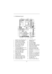
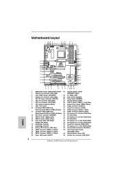
...43 42 PCIE1 PWR_FAN1 Chipset 16 17 CD1 41 40 39 AUDIO CODEC PCIE2 IDE1 18 38 PCIE3 37 PCI1 SATA3_5_6 Super I/O 990FX Extreme4 AMD 19 SATA3_3_4 36 PCIE4 SB950 Support 8-Core CPU SATA3 6Gb/s Chipset 20 PCI Express 2.0 35 34 SATA3_8 SATA3_7 1 PCI2 ...32 31 30 29 28 27 26 25 24 1 HDMI_SPDIF Header (HDMI_SPDIF1, White) 23 Chassis Speaker Header 2 Chassis Fan Connector (CHA_FAN3) (SPEAKER 1, White) 3 Clear CMOS Jumper (CLRCMOS1) 24 Dr. Debug (LED) 4 Chassis Fan Connector (CHA_FAN2) 25 Reset Switch (RSTBTN) 5 ATX 12V Power Connector (ATX12V1) 26 Power Switch (...
...43 42 PCIE1 PWR_FAN1 Chipset 16 17 CD1 41 40 39 AUDIO CODEC PCIE2 IDE1 18 38 PCIE3 37 PCI1 SATA3_5_6 Super I/O 990FX Extreme4 AMD 19 SATA3_3_4 36 PCIE4 SB950 Support 8-Core CPU SATA3 6Gb/s Chipset 20 PCI Express 2.0 35 34 SATA3_8 SATA3_7 1 PCI2 ...32 31 30 29 28 27 26 25 24 1 HDMI_SPDIF Header (HDMI_SPDIF1, White) 23 Chassis Speaker Header 2 Chassis Fan Connector (CHA_FAN3) (SPEAKER 1, White) 3 Clear CMOS Jumper (CLRCMOS1) 24 Dr. Debug (LED) 4 Chassis Fan Connector (CHA_FAN2) 25 Reset Switch (RSTBTN) 5 ATX 12V Power Connector (ATX12V1) 26 Power Switch (...

User Manual
Page 13
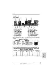
... 16 17 18 Microphone (Pink) USB 3.0 Ports (USB23) IEEE 1394 Port (IEEE 1394) eSATA3 Connector USB 2.0 Ports (USB67) USB 2.0 Ports (USB01) Optical SPDIF Out Port Clear CMOS Switch (CLRCBTN) PS/2 Keyboard Port (Purple) * There are two LED next to the table below for connection details in accordance with the type of speaker...
... 16 17 18 Microphone (Pink) USB 3.0 Ports (USB23) IEEE 1394 Port (IEEE 1394) eSATA3 Connector USB 2.0 Ports (USB67) USB 2.0 Ports (USB01) Optical SPDIF Out Port Clear CMOS Switch (CLRCBTN) PS/2 Keyboard Port (Purple) * There are two LED next to the table below for connection details in accordance with the type of speaker...

User Manual
Page 29
...please turn off the computer and unplug the power cord from the power supply. Jumper Setting Clear CMOS Jumper (CLRCMOS1) (see p.12, No. 3) Default Clear CMOS Note: CLRCMOS1 allows you update the BIOS. The Clear CMOS Switch has the same function as system password, date, time, and system setup parameters. ...boot up the system first, and then shut it down before you do not clear the CMOS right after you to clear the data in CMOS includes system setup information such as the Clear CMOS jumper. 29 2.8 Jumpers Setup The illustration shows how jumpers are "Short" when jumper ...
...please turn off the computer and unplug the power cord from the power supply. Jumper Setting Clear CMOS Jumper (CLRCMOS1) (see p.12, No. 3) Default Clear CMOS Note: CLRCMOS1 allows you update the BIOS. The Clear CMOS Switch has the same function as system password, date, time, and system setup parameters. ...boot up the system first, and then shut it down before you do not clear the CMOS right after you to clear the data in CMOS includes system setup information such as the Clear CMOS jumper. 29 2.8 Jumpers Setup The illustration shows how jumpers are "Short" when jumper ...

User Manual
Page 37
Power Switch (PWRBTN) (see p.12 No. 26) Power Switch is a smart switch, allowing users to quickly turn on /off or reset the system or clear the CMOS values. Reset Switch (RSTBTN) (see p.13 No. 17) Clear CMOS Switch is a smart switch, allowing users to quickly reset the system. Clear CMOS Switch (CLRCBTN) (see p.12 No. 25) Reset Switch is a smart switch, allowing users to quickly clear the CMOS values 37 2.10 Smart Switches This motherboard has three smart switches: power switch, reset switch and clear CMOS switch, allowing users to quickly turn on /off the system.
Power Switch (PWRBTN) (see p.12 No. 26) Power Switch is a smart switch, allowing users to quickly turn on /off or reset the system or clear the CMOS values. Reset Switch (RSTBTN) (see p.13 No. 17) Clear CMOS Switch is a smart switch, allowing users to quickly reset the system. Clear CMOS Switch (CLRCBTN) (see p.12 No. 25) Reset Switch is a smart switch, allowing users to quickly clear the CMOS values 37 2.10 Smart Switches This motherboard has three smart switches: power switch, reset switch and clear CMOS switch, allowing users to quickly turn on /off the system.
Quick Installation Guide
Page 2
...) 21 SATA3 Connector (SATA3_1_2, White) 44 Infrared Module Header (IR1) 22 Power LED Header (PLED1) 45 Chassis Fan Connector (CHA_FAN1) 2 ASRock 990FX Extreme4 Motherboard English White) (FRONT_1394, White) 39 PCI Express 2.0 x16 Slot (PCIE2; Blue) 14 USB 2.0 Header (USB2_3, Blue) 37 PCI Slot... 28 27 26 25 24 1 HDMI_SPDIF Header (HDMI_SPDIF1, White) 23 Chassis Speaker Header 2 Chassis Fan Connector (CHA_FAN3) (SPEAKER 1, White) 3 Clear CMOS Jumper (CLRCMOS1) 24 Dr. Debug (LED) 4 Chassis Fan Connector (CHA_FAN2) 25 Reset Switch (RSTBTN) 5 ATX 12V Power Connector (ATX12V1)...
...) 21 SATA3 Connector (SATA3_1_2, White) 44 Infrared Module Header (IR1) 22 Power LED Header (PLED1) 45 Chassis Fan Connector (CHA_FAN1) 2 ASRock 990FX Extreme4 Motherboard English White) (FRONT_1394, White) 39 PCI Express 2.0 x16 Slot (PCIE2; Blue) 14 USB 2.0 Header (USB2_3, Blue) 37 PCI Slot... 28 27 26 25 24 1 HDMI_SPDIF Header (HDMI_SPDIF1, White) 23 Chassis Speaker Header 2 Chassis Fan Connector (CHA_FAN3) (SPEAKER 1, White) 3 Clear CMOS Jumper (CLRCMOS1) 24 Dr. Debug (LED) 4 Chassis Fan Connector (CHA_FAN2) 25 Reset Switch (RSTBTN) 5 ATX 12V Power Connector (ATX12V1)...
Quick Installation Guide
Page 3
... Rear Speaker Central / Bass Side Speaker (No. 9) (No. 6) (No. 7) (No. 5) 2 V -- -- -- 4 V V -- -- 6 V V V -- 8 V V V V English 3 ASRock 990FX Extreme4 Motherboard I/O Panel 1 2 3 4 58 69 7 10 18 17 16 15 1 PS/2 Mouse Port (Green) 2 Coaxial SPDIF Out Port *3 LAN RJ-45 Port 4 USB 2.0 Ports (USB45) 5 Side...USB23) IEEE 1394 Port (IEEE 1394) eSATA3 Connector USB 2.0 Ports (USB67) USB 2.0 Ports (USB01) Optical SPDIF Out Port Clear CMOS Switch (CLRCBTN) PS/2 Keyboard Port (Purple) * There are two LED next to the table below for connection details in accordance ...
... Rear Speaker Central / Bass Side Speaker (No. 9) (No. 6) (No. 7) (No. 5) 2 V -- -- -- 4 V V -- -- 6 V V V -- 8 V V V V English 3 ASRock 990FX Extreme4 Motherboard I/O Panel 1 2 3 4 58 69 7 10 18 17 16 15 1 PS/2 Mouse Port (Green) 2 Coaxial SPDIF Out Port *3 LAN RJ-45 Port 4 USB 2.0 Ports (USB45) 5 Side...USB23) IEEE 1394 Port (IEEE 1394) eSATA3 Connector USB 2.0 Ports (USB67) USB 2.0 Ports (USB01) Optical SPDIF Out Port Clear CMOS Switch (CLRCBTN) PS/2 Keyboard Port (Purple) * There are two LED next to the table below for connection details in accordance ...

Quick Installation Guide
Page 7
... EJ168A, supports USB 1.0/2.0/3.0 up to -Use USB 3.0 Ports - 1 x eSATA3 Connector - 1 x RJ-45 LAN Port with LED (ACT/LINK LED and SPEED LED) - 1 x IEEE 1394 Port - 1 x Clear CMOS Switch with LED 7 ASRock 990FX Extreme4 Motherboard English Front panel audio connector - 2 x USB 2.0 headers (support 4 USB 2.0 ports) - 1 x USB 3.0 header (supports 2 USB 3.0 ports) - 1 x Dr. Debug (7-Segment Debug LED...
... EJ168A, supports USB 1.0/2.0/3.0 up to -Use USB 3.0 Ports - 1 x eSATA3 Connector - 1 x RJ-45 LAN Port with LED (ACT/LINK LED and SPEED LED) - 1 x IEEE 1394 Port - 1 x Clear CMOS Switch with LED 7 ASRock 990FX Extreme4 Motherboard English Front panel audio connector - 2 x USB 2.0 headers (support 4 USB 2.0 ports) - 1 x USB 3.0 header (supports 2 USB 3.0 ports) - 1 x Dr. Debug (7-Segment Debug LED...

Quick Installation Guide
Page 26
...and MAC address will be cleared only if the CMOS battery is placed on CLRCMOS1 for 15 seconds, use a jumper cap to default setup, please turn off the computer and unplug the power cord from the power supply. English 26 ASRock 990FX Extreme4 Motherboard 2.8 Jumpers Setup The... illustration shows how jumpers are "Short" when jumper cap is placed on pins, the jumper is "Short". The illustration shows a 3-pin jumper whose pin1 and pin2 are setup. The Clear CMOS Switch has the same function as the Clear CMOS jumper...
...and MAC address will be cleared only if the CMOS battery is placed on CLRCMOS1 for 15 seconds, use a jumper cap to default setup, please turn off the computer and unplug the power cord from the power supply. English 26 ASRock 990FX Extreme4 Motherboard 2.8 Jumpers Setup The... illustration shows how jumpers are "Short" when jumper cap is placed on pins, the jumper is "Short". The illustration shows a 3-pin jumper whose pin1 and pin2 are setup. The Clear CMOS Switch has the same function as the Clear CMOS jumper...

Quick Installation Guide
Page 33
...switch, allowing users to quickly reset the system. Reset Switch (RSTBTN) (see p.3 No. 17) Clear CMOS Switch is a smart switch, allowing users to quickly clear the CMOS values 33 ASRock 990FX Extreme4 Motherboard Power Switch (PWRBTN) (see p.2 No. 26) Power Switch is a smart switch, allowing... users to quickly turn on /off or reset the system or clear the CMOS values. rear USB 3.0 bracket together...
...switch, allowing users to quickly reset the system. Reset Switch (RSTBTN) (see p.3 No. 17) Clear CMOS Switch is a smart switch, allowing users to quickly clear the CMOS values 33 ASRock 990FX Extreme4 Motherboard Power Switch (PWRBTN) (see p.2 No. 26) Power Switch is a smart switch, allowing... users to quickly turn on /off or reset the system or clear the CMOS values. rear USB 3.0 bracket together...

Quick Installation Guide
Page 201
2.7 그림은 3 1-2 쇼트 오픈 점퍼 CMOS 초기화 (CLRCMOS1, 3 2 3 세팅 CMOS 삭제 참고 : CLRCMOS1 CMOS 15 CLRCMOS1 의 핀 2 와 핀 3 을 5 BIOS CMOS BIOS CMOS CMOS CMOS 1394 GUID, MAC Clear CMOS Switch는 Clear CMOS 한국어 201 ASRock 990FX Extreme4 Motherboard
2.7 그림은 3 1-2 쇼트 오픈 점퍼 CMOS 초기화 (CLRCMOS1, 3 2 3 세팅 CMOS 삭제 참고 : CLRCMOS1 CMOS 15 CLRCMOS1 의 핀 2 와 핀 3 을 5 BIOS CMOS BIOS CMOS CMOS CMOS 1394 GUID, MAC Clear CMOS Switch는 Clear CMOS 한국어 201 ASRock 990FX Extreme4 Motherboard

Quick Installation Guide
Page 271
2.7 3 針 1 和針腳 2 短接 開路 CMOS (CLRCMOS1, 3 2 頁第 3 項 ) 設定 默認設置 清除 CMOS 註: C L R C M O S1 C M O S 15 CLRCMOS1 的 pin2 及 pin3 短路 5 BIOS CMOS BIOS CMOS CMOS C M O S 1394 GUID 及 MAC Clear CMOS Clear CMOS 繁體中文 271 ASRock 990FX Extreme4 Motherboard
2.7 3 針 1 和針腳 2 短接 開路 CMOS (CLRCMOS1, 3 2 頁第 3 項 ) 設定 默認設置 清除 CMOS 註: C L R C M O S1 C M O S 15 CLRCMOS1 的 pin2 及 pin3 短路 5 BIOS CMOS BIOS CMOS CMOS C M O S 1394 GUID 及 MAC Clear CMOS Clear CMOS 繁體中文 271 ASRock 990FX Extreme4 Motherboard

