

User Manual
Page 3
... 2.1 CPU Installation 16 2.2 Installation of CPU Fan and Heatsink 16 2.3 Installation of Memory Modules (DIMM 17 2.4 Expansion Slots (PCI and PCI Express Slots 19 2.5 SLITM and Quad SLITM Operation Guide 20 2.6 CrossFireXTM, 3-Way CrossFireXTM and Quad CrossFireXTM Operation Guide 23 2.7 Surround Display Information 28 2.8 Jumpers Setup 29 2.9 Onboard Headers and Connectors 30 2.10 Smart Switches 37 2.11 Dr. Debug 38 2.12 Serial ATA3 (SATA3) Hard Disks Installation 42 2.13 Hot Plug and Hot Swap Functions for SATA3 HDDs 42...
... 2.1 CPU Installation 16 2.2 Installation of CPU Fan and Heatsink 16 2.3 Installation of Memory Modules (DIMM 17 2.4 Expansion Slots (PCI and PCI Express Slots 19 2.5 SLITM and Quad SLITM Operation Guide 20 2.6 CrossFireXTM, 3-Way CrossFireXTM and Quad CrossFireXTM Operation Guide 23 2.7 Surround Display Information 28 2.8 Jumpers Setup 29 2.9 Onboard Headers and Connectors 30 2.10 Smart Switches 37 2.11 Dr. Debug 38 2.12 Serial ATA3 (SATA3) Hard Disks Installation 42 2.13 Hot Plug and Hot Swap Functions for SATA3 HDDs 42...

User Manual
Page 5
... VGA cards and CPU support lists on ASRock website without notice. Introduction Thank you are using. Because the motherboard specifications and the BIOS software might be subject to this manual will be available on ASRock website as well. To get better performance in Windows® 7 / 7 64-bit / VistaTM / VistaTM 64 bit, it is recommended to set the BIOS option in Floppy Drive 4 x Serial ATA (SATA) Data Cables (Optional) 2 x Serial ATA (SATA) HDD Power Cables (Optional) 1 x 3.5mm Audio Cable (Optional) 1 x I/O Panel Shield 1 x Front USB 3.0 Panel 4 x HDD...
... VGA cards and CPU support lists on ASRock website without notice. Introduction Thank you are using. Because the motherboard specifications and the BIOS software might be subject to this manual will be available on ASRock website as well. To get better performance in Windows® 7 / 7 64-bit / VistaTM / VistaTM 64 bit, it is recommended to set the BIOS option in Floppy Drive 4 x Serial ATA (SATA) Data Cables (Optional) 2 x Serial ATA (SATA) HDD Power Cables (Optional) 1 x 3.5mm Audio Cable (Optional) 1 x I/O Panel Shield 1 x Front USB 3.0 Panel 4 x HDD...
User Manual
Page 9
... instant performance boost. ASRock UCC (Unlock CPU Core) feature simplifies AMD CPU activation. This motherboard supports Dual Channel Memory Technology. ASRock website http://www.asrock.com 5. In Hardware Monitor, it shows the fan speed and temperature for system usage under Windows® 7 / VistaTM / XP. In Overclocking, you adopt. It should be less than 4GB for the reservation for you to adjust. As long as a profile and share...
... instant performance boost. ASRock UCC (Unlock CPU Core) feature simplifies AMD CPU activation. This motherboard supports Dual Channel Memory Technology. ASRock website http://www.asrock.com 5. In Hardware Monitor, it shows the fan speed and temperature for system usage under Windows® 7 / VistaTM / XP. In Overclocking, you adopt. It should be less than 4GB for the reservation for you to adjust. As long as a profile and share...

User Manual
Page 10
... Windows®. Please visit our website for you - With APP Charger driver installed, you can press key during the POST or press key to BIOS setup menu to access ASRock Instant Flash. ASRock motherboards are idle without sacrificing computing performance. ASRock XFast USB can easily enjoy the marvelous charging experience than ever. This motherboard also provides a free 3.5mm audio cable (optional) that helps you keep in a few clicks without entering...
... Windows®. Please visit our website for you - With APP Charger driver installed, you can press key during the POST or press key to BIOS setup menu to access ASRock Instant Flash. ASRock motherboards are idle without sacrificing computing performance. ASRock XFast USB can easily enjoy the marvelous charging experience than ever. This motherboard also provides a free 3.5mm audio cable (optional) that helps you keep in a few clicks without entering...
User Manual
Page 12
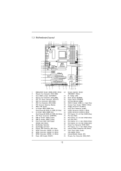
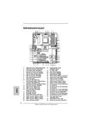
...) 23 Chassis Speaker Header 2 Chassis Fan Connector (CHA_FAN3) (SPEAKER 1, White) 3 Clear CMOS Jumper (CLRCMOS1) 24 Dr. Debug (LED) 4 Chassis Fan Connector (CHA_FAN2) 25 Reset Switch (RSTBTN) 5 ATX 12V Power Connector (ATX12V1) 26 Power Switch (PWRBTN) 6 CPU Fan Connector (CPU_FAN1) 27 SPI Flash Memory (32Mb) 7 CPU Fan Connector (CPU_FAN2) 28 USB 3.0 Header (USB3_0_1, Light Blue) 8 CPU Heatsink Retention Module 29 System Panel Header (PANEL1, White) 9 AM3+ CPU Socket 30 Floppy Connector (FLOPPY1) 10 2 x 240-pin DDR3 DIMM Slots 31 Serial Port Connector (COM1) (Dual Channel...
...) 23 Chassis Speaker Header 2 Chassis Fan Connector (CHA_FAN3) (SPEAKER 1, White) 3 Clear CMOS Jumper (CLRCMOS1) 24 Dr. Debug (LED) 4 Chassis Fan Connector (CHA_FAN2) 25 Reset Switch (RSTBTN) 5 ATX 12V Power Connector (ATX12V1) 26 Power Switch (PWRBTN) 6 CPU Fan Connector (CPU_FAN1) 27 SPI Flash Memory (32Mb) 7 CPU Fan Connector (CPU_FAN2) 28 USB 3.0 Header (USB3_0_1, Light Blue) 8 CPU Heatsink Retention Module 29 System Panel Header (PANEL1, White) 9 AM3+ CPU Socket 30 Floppy Connector (FLOPPY1) 10 2 x 240-pin DDR3 DIMM Slots 31 Serial Port Connector (COM1) (Dual Channel...

User Manual
Page 27
... Catalyst Control Center" on your sys- 2.6.2 Driver Installation and Setup Step 1. For Windows® XP OS: A. Click "View", select "CrossFireXTM", and then check the item "Enable CrossFireXTM". We recommend using this utility to installation. Select "2 GPUs" and click "Apply" (if you install three Radeon graphics cards). 27 Install the required drivers to your system, and restart your system, there is an optional download. Install the VGA card drivers to your...
... Catalyst Control Center" on your sys- 2.6.2 Driver Installation and Setup Step 1. For Windows® XP OS: A. Click "View", select "CrossFireXTM", and then check the item "Enable CrossFireXTM". We recommend using this utility to installation. Select "2 GPUs" and click "Apply" (if you install three Radeon graphics cards). 27 Install the required drivers to your system, and restart your system, there is an optional download. Install the VGA card drivers to your...

User Manual
Page 38
... specific) Pre-Memory North Bridge initialization (North Bridge module specific) Pre-memory South Bridge initialization is started CPU post-memory initialization. Boot Strap Processor (BSP) selection CPU post-memory initialization. Please see ASL Status Codes section below for reading the Dr. Debug codes. Programming memory timing information Memory initialization. Application Processor(s) (AP) initialization CPU post-memory initialization. 2.11 Dr. Debug Dr. Debug is used Power on. Memory presence detection Memory initialization.
... specific) Pre-Memory North Bridge initialization (North Bridge module specific) Pre-memory South Bridge initialization is started CPU post-memory initialization. Boot Strap Processor (BSP) selection CPU post-memory initialization. Please see ASL Status Codes section below for reading the Dr. Debug codes. Programming memory timing information Memory initialization. Application Processor(s) (AP) initialization CPU post-memory initialization. 2.11 Dr. Debug Dr. Debug is used Power on. Memory presence detection Memory initialization.

User Manual
Page 41
... 0xDA 0xDB 0xDC SCSI Detect SCSI Enable Setup Verifying Password Start of Setup Reserved for ASL (see ASL Status Codes section below) Setup Input Wait Reserved for ASL (see ASL Status Codes section below) Ready To Boot event Legacy Boot event Exit Boot Services event Runtime Set Virtual Address MAP Begin Runtime Set Virtual Address MAP End Legacy Option ROM Initialization System Reset USB hot plug PCI bus hot plug Clean-up of NVRAM Confi...
... 0xDA 0xDB 0xDC SCSI Detect SCSI Enable Setup Verifying Password Start of Setup Reserved for ASL (see ASL Status Codes section below) Setup Input Wait Reserved for ASL (see ASL Status Codes section below) Ready To Boot event Legacy Boot event Exit Boot Services event Runtime Set Virtual Address MAP Begin Runtime Set Virtual Address MAP End Legacy Option ROM Initialization System Reset USB hot plug PCI bus hot plug Clean-up of NVRAM Confi...

User Manual
Page 43
SATA data cable (Red) B. Points of our motherboard is indicated in RAID / AHCI mode. Make sure to power supply 1. Below operation procedure is definitely not able to reduce the risk of Hot Plug feature carefully. The SATA3 HDD, which cannot support Hot Plug function, will cause the HDD damage and data loss. Please follow below instructions step by the chipset because of its limitation...
SATA data cable (Red) B. Points of our motherboard is indicated in RAID / AHCI mode. Make sure to power supply 1. Below operation procedure is definitely not able to reduce the risk of Hot Plug feature carefully. The SATA3 HDD, which cannot support Hot Plug function, will cause the HDD damage and data loss. Please follow below instructions step by the chipset because of its limitation...

User Manual
Page 45
... a window for boot devices selection appears. A. During POST at the beginning of 2 or more SATA3 HDDs with RAID functions, please follow the order from up UEFI. D. Start to [RAID]. Enter UEFI SETUP UTILITY Advanced screen Storage Configuration. STEP 2: Make a SATA3 Driver Diskette. Please insert a floppy diskette into your optical drive to boot your optical drive first. The system will lose ALL data in it! B. Set the "SATA Mode" option...
... a window for boot devices selection appears. A. During POST at the beginning of 2 or more SATA3 HDDs with RAID functions, please follow the order from up UEFI. D. Start to [RAID]. Enter UEFI SETUP UTILITY Advanced screen Storage Configuration. STEP 2: Make a SATA3 Driver Diskette. Please insert a floppy diskette into your optical drive to boot your optical drive first. The system will lose ALL data in it! B. Set the "SATA Mode" option...

User Manual
Page 59
... ports, please disable this item to RAID mode, it is suggested to enable or disable Onboard Marvell SATA3 Option ROM. The default value is [IDE Mode]. The default value is [Enabled]. SATA IDE Combined Mode This item is for SATA3_1 to SATA3_6 ports.Use this item to adjust the "Marvell SATA3 Operation Mode" feature. Configuration options: [AHCI Mode], [RAID Mode] and [IDE Mode]. Use this item to enable or disable SATA IDE combined mode. If Option ROM is disabled, UEFI cannot use the SATA device to connect to SATA3_6 ports. 3.4.4 Storage Configuration SATA Controller...
... ports, please disable this item to RAID mode, it is suggested to enable or disable Onboard Marvell SATA3 Option ROM. The default value is [IDE Mode]. The default value is [Enabled]. SATA IDE Combined Mode This item is for SATA3_1 to SATA3_6 ports.Use this item to adjust the "Marvell SATA3 Operation Mode" feature. Configuration options: [AHCI Mode], [RAID Mode] and [IDE Mode]. Use this item to enable or disable SATA IDE combined mode. If Option ROM is disabled, UEFI cannot use the SATA device to connect to SATA3_6 ports. 3.4.4 Storage Configuration SATA Controller...

User Manual
Page 69
Because motherboard settings and hardware options vary, use the setup procedures in this chapter for more about ASRock, welcome to display the menus. 4.2.2 Drivers Menu The Drivers Menu shows the available devices drivers if the system detects the installed devices. The CD automatically displays the Main Menu if "AUTORUN" is enabled in the Support CD to visit ASRock's website at http://www.asrock.com; If the Main Menu did not appear automatically, locate and double click...
Because motherboard settings and hardware options vary, use the setup procedures in this chapter for more about ASRock, welcome to display the menus. 4.2.2 Drivers Menu The Drivers Menu shows the available devices drivers if the system detects the installed devices. The CD automatically displays the Main Menu if "AUTORUN" is enabled in the Support CD to visit ASRock's website at http://www.asrock.com; If the Main Menu did not appear automatically, locate and double click...
Quick Installation Guide
Page 2
...) 23 Chassis Speaker Header 2 Chassis Fan Connector (CHA_FAN3) (SPEAKER 1, White) 3 Clear CMOS Jumper (CLRCMOS1) 24 Dr. Debug (LED) 4 Chassis Fan Connector (CHA_FAN2) 25 Reset Switch (RSTBTN) 5 ATX 12V Power Connector (ATX12V1) 26 Power Switch (PWRBTN) 6 CPU Fan Connector (CPU_FAN1) 27 SPI Flash Memory (32Mb) 7 CPU Fan Connector (CPU_FAN2) 28 USB 3.0 Header (USB3_0_1, Light Blue) 8 CPU Heatsink Retention Module 29 System Panel Header (PANEL1, White) 9 AM3+ CPU Socket 30 Floppy Connector (FLOPPY1) 10 2 x 240-pin DDR3 DIMM Slots 31 Serial Port Connector (COM1) (Dual Channel...
...) 23 Chassis Speaker Header 2 Chassis Fan Connector (CHA_FAN3) (SPEAKER 1, White) 3 Clear CMOS Jumper (CLRCMOS1) 24 Dr. Debug (LED) 4 Chassis Fan Connector (CHA_FAN2) 25 Reset Switch (RSTBTN) 5 ATX 12V Power Connector (ATX12V1) 26 Power Switch (PWRBTN) 6 CPU Fan Connector (CPU_FAN1) 27 SPI Flash Memory (32Mb) 7 CPU Fan Connector (CPU_FAN2) 28 USB 3.0 Header (USB3_0_1, Light Blue) 8 CPU Heatsink Retention Module 29 System Panel Header (PANEL1, White) 9 AM3+ CPU Socket 30 Floppy Connector (FLOPPY1) 10 2 x 240-pin DDR3 DIMM Slots 31 Serial Port Connector (COM1) (Dual Channel...
Quick Installation Guide
Page 3
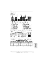
... Microphone (Pink) USB 3.0 Ports (USB23) IEEE 1394 Port (IEEE 1394) eSATA3 Connector USB 2.0 Ports (USB67) USB 2.0 Ports (USB01) Optical SPDIF Out Port Clear CMOS Switch (CLRCBTN) PS/2 Keyboard Port (Purple) * There are two LED next to the table below for connection details in accordance with the type of speaker you use . Please refer to the LAN port. TABLE for the LAN port LED indications. LAN Port LED Indications Activity/Link LED SPEED LED Status Description Status Description ACT/LINK SPEED LED LED Off No...
... Microphone (Pink) USB 3.0 Ports (USB23) IEEE 1394 Port (IEEE 1394) eSATA3 Connector USB 2.0 Ports (USB67) USB 2.0 Ports (USB01) Optical SPDIF Out Port Clear CMOS Switch (CLRCBTN) PS/2 Keyboard Port (Purple) * There are two LED next to the table below for connection details in accordance with the type of speaker you use . Please refer to the LAN port. TABLE for the LAN port LED indications. LAN Port LED Indications Activity/Link LED SPEED LED Status Description Status Description ACT/LINK SPEED LED LED Off No...

Quick Installation Guide
Page 9
... motherboard supports Dual Channel Memory Technology. For audio output, this motherboard supports both stereo and mono modes. CAUTION! 1. Please read the installation guide of your system. Before you are not responsible for you can load the OC profile to adjust. ASRock Extreme Tuning Utility (AXTU) is an all-in a user-friendly interface, which means you to 9 ASRock 990FX Extreme4 Motherboard English This motherboard supports Untied Overclocking Technology. In Hardware Monitor, it shows the fan speed and temperature...
... motherboard supports Dual Channel Memory Technology. For audio output, this motherboard supports both stereo and mono modes. CAUTION! 1. Please read the installation guide of your system. Before you are not responsible for you can load the OC profile to adjust. ASRock Extreme Tuning Utility (AXTU) is an all-in a user-friendly interface, which means you to 9 ASRock 990FX Extreme4 Motherboard English This motherboard supports Untied Overclocking Technology. In Hardware Monitor, it shows the fan speed and temperature...
Quick Installation Guide
Page 10
... into Standby mode (S1), Suspend to get the same OC settings. This motherboard also provides a free 3.5mm audio cable (optional) that combines your most convenient computing environment. 13. In IES (Intelligent Energy Saver), the voltage regulator can boost USB storage device performance. ASRock APP Charger. With APP Charger driver installed, you can easily enjoy the marvelous charging experience than the recommended CPU 10 ASRock 990FX Extreme4 Motherboard English Frequencies other...
... into Standby mode (S1), Suspend to get the same OC settings. This motherboard also provides a free 3.5mm audio cable (optional) that combines your most convenient computing environment. 13. In IES (Intelligent Energy Saver), the voltage regulator can boost USB storage device performance. ASRock APP Charger. With APP Charger driver installed, you can easily enjoy the marvelous charging experience than the recommended CPU 10 ASRock 990FX Extreme4 Motherboard English Frequencies other...

Quick Installation Guide
Page 24
... your computer and boot into OS. tem. The Catalyst Uninstaller is no need to be installed (If you will find "ATI Catalyst Control Center" on your computer. Step 5. English 24 ASRock 990FX Extreme4 Motherboard Step 3. For Windows® XP OS: A. Please check AMD website for ATITM driver updates. Power on your system, there is an optional download. AMDTM recommends Windows® XP Service Pack 2 or...
... your computer and boot into OS. tem. The Catalyst Uninstaller is no need to be installed (If you will find "ATI Catalyst Control Center" on your computer. Step 5. English 24 ASRock 990FX Extreme4 Motherboard Step 3. For Windows® XP OS: A. Please check AMD website for ATITM driver updates. Power on your system, there is an optional download. AMDTM recommends Windows® XP Service Pack 2 or...
Quick Installation Guide
Page 40
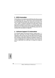
... your CD-ROM drive. When you start up the computer, please press or during the Power-On-Self-Test (POST) to enter BIOS Setup after POST, please restart the system by pressing + + , or pressing the reset button on the motherboard stores BIOS Setup Utility. Software Support CD information This motherboard supports various Microsoft® Windows® operating systems: 7 / 7 64-bit / VistaTM / VistaTM 64-bit / XP / XP 64-bit. To begin using the Support CD, insert...
... your CD-ROM drive. When you start up the computer, please press or during the Power-On-Self-Test (POST) to enter BIOS Setup after POST, please restart the system by pressing + + , or pressing the reset button on the motherboard stores BIOS Setup Utility. Software Support CD information This motherboard supports various Microsoft® Windows® operating systems: 7 / 7 64-bit / VistaTM / VistaTM 64-bit / XP / XP 64-bit. To begin using the Support CD, insert...

RAID Installation Guide
Page 5
After reading the floppy disk, the driver will be presented. A. STEP 4: Install Windows® 7 / 7 64-bit / VistaTM / VistaTM 64-bit OS on your system. After step 1, 2, 3, you want to install Windows® 7 / 7 64-bit / VistaTM / VistaTM 64-bit on your system. Enter UEFI SETUP UTILITY → Advanced screen → Storage Configuration. Set the "SATA Mode" option to check this document for details. B. Please refer to the BIOS RAID installation guide part in this RAID installation guide for proper configuration. When prompted, insert...
After reading the floppy disk, the driver will be presented. A. STEP 4: Install Windows® 7 / 7 64-bit / VistaTM / VistaTM 64-bit OS on your system. After step 1, 2, 3, you want to install Windows® 7 / 7 64-bit / VistaTM / VistaTM 64-bit on your system. Enter UEFI SETUP UTILITY → Advanced screen → Storage Configuration. Set the "SATA Mode" option to check this document for details. B. Please refer to the BIOS RAID installation guide part in this RAID installation guide for proper configuration. When prompted, insert...
RAID Installation Guide
Page 10
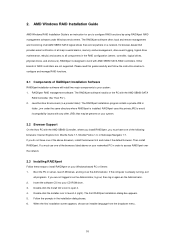
... 7.1. Insert the software CD into your system. 2.2 Browser Support On the Host PC with AMD SB950 SATA RAID controllers. The RAIDXpert software offers local and remote management and monitoring of the browsers listed above browsers, install the browser first and make it . 4. RAIDXpert RAID management software: The RAIDXpert software installs on your CD-ROM drive. 3. Follow the prompts in the RAID configuration (server, controller, logical drives, physical drives, and enclosure). Java...
... 7.1. Insert the software CD into your system. 2.2 Browser Support On the Host PC with AMD SB950 SATA RAID controllers. The RAIDXpert software offers local and remote management and monitoring of the browsers listed above browsers, install the browser first and make it . 4. RAIDXpert RAID management software: The RAIDXpert software installs on your CD-ROM drive. 3. Follow the prompts in the RAID configuration (server, controller, logical drives, physical drives, and enclosure). Java...


