
User Manual
Page 4
... guration 57 3.4.4 Storage Conf guration 58 3.4.5 Super IO Conf guration 59 3.4.6 ACPI Conf guration 60 3.4.7 USB Conf guration 62 3.5 Hardware Health Event Monitoring Screen 63 3.6 Boot Screen 64 3.7 Security Screen 65 3.8 Exit Screen 66 4.
... guration 57 3.4.4 Storage Conf guration 58 3.4.5 Super IO Conf guration 59 3.4.6 ACPI Conf guration 60 3.4.7 USB Conf guration 62 3.5 Hardware Health Event Monitoring Screen 63 3.6 Boot Screen 64 3.7 Security Screen 65 3.8 Exit Screen 66 4.
User Manual
Page 8
... the components and devices of your own risk and expense. Supports jumperfree - ASRock Instant Boot - ASRock SmartView (see CAUTION 15) * For detailed product information, please visit our website: http://www.asrock.com WARNING Please realize that there is required) (see CAUTION 10) - Boot Failure Guard (B.F.G.) - Chassis Temperature Sensing - ErP/EuP Ready (ErP/EuP ready power...
... the components and devices of your own risk and expense. Supports jumperfree - ASRock Instant Boot - ASRock SmartView (see CAUTION 15) * For detailed product information, please visit our website: http://www.asrock.com WARNING Please realize that there is required) (see CAUTION 10) - Boot Failure Guard (B.F.G.) - Chassis Temperature Sensing - ErP/EuP Ready (ErP/EuP ready power...
User Manual
Page 27
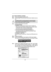
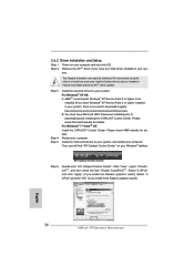
... it again): http://www.microsoft.com/windowsxp/sp2/default.mspx B. Install the VGA card drivers to uninstall any VGA driver installed in your computer and boot into OS. ATI Catalyst Control Center Step 6. For Windows® XP OS: A. Remove the AMDTM driver if you will f nd "ATI Catalyst Control Center" on...
... it again): http://www.microsoft.com/windowsxp/sp2/default.mspx B. Install the VGA card drivers to uninstall any VGA driver installed in your computer and boot into OS. ATI Catalyst Control Center Step 6. For Windows® XP OS: A. Remove the AMDTM driver if you will f nd "ATI Catalyst Control Center" on...
User Manual
Page 29
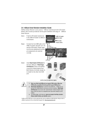
...The Multi-Angle CIR Receiver does not support Hot-Plug function. Please refer to the USB 2.0 header on the rear panel. 2.8 ASRock Smart Remote Installation Guide ASRock Smart Remote is compatible with CIR header . Step1. Install Multi-Angle CIR Receiver to the USB_PWR P- When the CIR function is only... supported by some of the chassis on the market. 3. Step2. Please install it before you boot the system. * ASRock Smart Remote is enabled, the other front USB port. 3 CIR sensors in different angles 1. Find the CIR header located next to...
...The Multi-Angle CIR Receiver does not support Hot-Plug function. Please refer to the USB 2.0 header on the rear panel. 2.8 ASRock Smart Remote Installation Guide ASRock Smart Remote is compatible with CIR header . Step1. Install Multi-Angle CIR Receiver to the USB_PWR P- When the CIR function is only... supported by some of the chassis on the market. 3. Step2. Please install it before you boot the system. * ASRock Smart Remote is enabled, the other front USB port. 3 CIR sensors in different angles 1. Find the CIR header located next to...

User Manual
Page 30
... allows you update the BIOS. The data in CMOS. If you need to clear the CMOS when you just f nish updating the BIOS, you must boot up the system f rst, and then shut it down before you do not clear the CMOS right after you to default setup, please turn of...
... allows you update the BIOS. The data in CMOS. If you need to clear the CMOS when you just f nish updating the BIOS, you must boot up the system f rst, and then shut it down before you do not clear the CMOS right after you to default setup, please turn of...

User Manual
Page 37
... - 0x2A 0x2B 0x2C 0x2D 0x2E 0x2F 0x30 0x31 0x32 0x33 0x34 0x35 0x36 Description Not used to provide code information, which makes troubleshooting even easier. Boot Strap Processor (BSP) selection CPU post-memory initialization. Serial Presence Detect (SPD) data reading Memory initialization. 2.12 Dr. Debug Dr. Debug is used Power on...
... - 0x2A 0x2B 0x2C 0x2D 0x2E 0x2F 0x30 0x31 0x32 0x33 0x34 0x35 0x36 Description Not used to provide code information, which makes troubleshooting even easier. Boot Strap Processor (BSP) selection CPU post-memory initialization. Serial Presence Detect (SPD) data reading Memory initialization. 2.12 Dr. Debug Dr. Debug is used Power on...

User Manual
Page 38
... reset PPI is not available Reserved for future AMI error codes S3 Resume is stared (S3 Resume PPI is called by the DXE IPL) S3 Boot Script execution Video repost OS S3 wake vector call Reserved for future AMI progress codes S3 Resume Failed S3 Resume PPI not Found S3 Resume... Boot Script Error S3 OS Wake Error Reserved for future AMI error codes Recovery condition triggered by f rmware (Auto recovery) Recovery condition triggered by user (Forced ...
... reset PPI is not available Reserved for future AMI error codes S3 Resume is stared (S3 Resume PPI is called by the DXE IPL) S3 Boot Script execution Video repost OS S3 wake vector call Reserved for future AMI progress codes S3 Resume Failed S3 Resume PPI not Found S3 Resume... Boot Script Error S3 OS Wake Error Reserved for future AMI error codes Recovery condition triggered by f rmware (Auto recovery) Recovery condition triggered by user (Forced ...

User Manual
Page 39
... module specif c) South Bridge DXE Initialization (South Bridge module specif c) ACPI module initialization CSM initialization Reserved for future AMI DXE codes OEM DXE initialization codes Boot Device Selection (BDS) phase is started Driver connecting is started PCI Bus initialization is started PCI Bus Hot Plug Controller Initialization PCI Bus Enumeration PCI...
... module specif c) South Bridge DXE Initialization (South Bridge module specif c) ACPI module initialization CSM initialization Reserved for future AMI DXE codes OEM DXE initialization codes Boot Device Selection (BDS) phase is started Driver connecting is started PCI Bus initialization is started PCI Bus Hot Plug Controller Initialization PCI Bus Enumeration PCI...
User Manual
Page 40
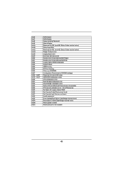
...ASL (see ASL Status Codes section below) Setup Input Wait Reserved for ASL (see ASL Status Codes section below) Ready To Boot event Legacy Boot event Exit Boot Services event Runtime Set Virtual Address MAP Begin Runtime Set Virtual Address MAP End Legacy Option ROM Initialization System Reset USB hot ... Bridge initialization error Some of Resources No Space for Legacy Option ROM No Console Output Devices are found Invalid password Error loading Boot Option (LoadImage returned error) Boot Option is failed (StartImage returned error) Flash update is failed Reset protocol is not available 40
...ASL (see ASL Status Codes section below) Setup Input Wait Reserved for ASL (see ASL Status Codes section below) Ready To Boot event Legacy Boot event Exit Boot Services event Runtime Set Virtual Address MAP Begin Runtime Set Virtual Address MAP End Legacy Option ROM Initialization System Reset USB hot ... Bridge initialization error Some of Resources No Space for Legacy Option ROM No Console Output Devices are found Invalid password Error loading Boot Option (LoadImage returned error) Boot Option is failed (StartImage returned error) Flash update is failed Reset protocol is not available 40
User Manual
Page 44
... drive to format the f oppy diskette and copy SATA3 drivers into the floppy drive. Insert the ASRock Support CD into the f oppy drive, and press any key. Please select CD-ROM as the boot device. WARNING! Please insert a f oppy diskette into your optical drive f rst. The system will start...64257;les [YN]? D. E. Then, the drivers compatible to [RAID]. B. Start to install Windows ® XP / XP 64-bit on a RAID disk composed of system boot-up UEFI. Therefore, the drivers you will lose ALL data in it! STEP 1: Set up , press key, and then a window for...
... drive to format the f oppy diskette and copy SATA3 drivers into the floppy drive. Insert the ASRock Support CD into the f oppy drive, and press any key. Please select CD-ROM as the boot device. WARNING! Please insert a f oppy diskette into your optical drive f rst. The system will start...64257;les [YN]? D. E. Then, the drivers compatible to [RAID]. B. Start to install Windows ® XP / XP 64-bit on a RAID disk composed of system boot-up UEFI. Therefore, the drivers you will lose ALL data in it! STEP 1: Set up , press key, and then a window for...

User Manual
Page 48
... system time/date information OC Tweaker To set up overclocking features Advanced To set up the advanced UEFI features H/W Monitor To display current hardware status Boot To set up the default system device to locate and load the Operating System Security To set up the computer . Please press or during the...
... system time/date information OC Tweaker To set up overclocking features Advanced To set up the advanced UEFI features H/W Monitor To display current hardware status Boot To set up the default system device to locate and load the Operating System Security To set up the computer . Please press or during the...

User Manual
Page 60
... the system from S5 using USB Keyboard/Remote. 60 USB Keyboard/Remote Power On Use this item to enable or disable Ring-In signals to boot up when the power recovers. Select [Auto] will enable this item to enable or disable R TC (Real Time Clock) to wake from the power-soft...
... the system from S5 using USB Keyboard/Remote. 60 USB Keyboard/Remote Power On Use this item to enable or disable Ring-In signals to boot up when the power recovers. Select [Auto] will enable this item to enable or disable R TC (Real Time Clock) to wake from the power-soft...

User Manual
Page 64
...is set to enable or disable OEM Logo. Full Screen Logo Use this item to [On], it will automatically activate the Numeric Lock function after boot-up. AddOn ROM Display Use this option to wait for you want to see the AddOn ROM information when the system... options: [Enabled] and [Disabled]. Setup Prompt Timeout This shows the number of seconds to adjust AddOn ROM Display. Boot From Onboard LAN Use this item to con f gure the boot settings and the boot priority. 3.6 Boot Screen In this section, it will display the available devices on your system for setup activation key. 65535...
...is set to enable or disable OEM Logo. Full Screen Logo Use this item to [On], it will automatically activate the Numeric Lock function after boot-up. AddOn ROM Display Use this option to wait for you want to see the AddOn ROM information when the system... options: [Enabled] and [Disabled]. Setup Prompt Timeout This shows the number of seconds to adjust AddOn ROM Display. Boot From Onboard LAN Use this item to con f gure the boot settings and the boot priority. 3.6 Boot Screen In this section, it will display the available devices on your system for setup activation key. 65535...
User Manual
Page 68
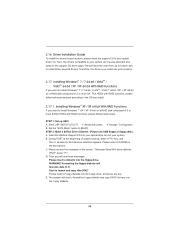
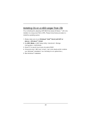
Choose the item "UEFI:xxx" to be installed on a HDD Larger Than 2TB This motherboard is adopting UEFI BIOS that allows Windows ® OS to boot. ("xxx" is an optical drive.) 5. Start Windows® installation. 68 Installing OS on a large size HDD (>2TB). Please make sure to install the operating system. 1. ... f les. Please follow below procedure to use Windows® VistaTM 64-bit (with SP1 or above) or Windows® 7 64-bit. 2. Press F11 to launch boot menu at system POST. 4.
Choose the item "UEFI:xxx" to be installed on a HDD Larger Than 2TB This motherboard is adopting UEFI BIOS that allows Windows ® OS to boot. ("xxx" is an optical drive.) 5. Start Windows® installation. 68 Installing OS on a large size HDD (>2TB). Please make sure to install the operating system. 1. ... f les. Please follow below procedure to use Windows® VistaTM 64-bit (with SP1 or above) or Windows® 7 64-bit. 2. Press F11 to launch boot menu at system POST. 4.
Quick Installation Guide
Page 8
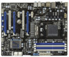
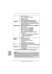
..., AMD Fusion, AMD Fusion Media Explorer, ASRock Software Suite (CyberLink DVD Suite - ASRock XFast USB (see CAUTION 13) - CPU Frequency Stepless Control (see CAUTION 11) - Turbo UCC Hardware - English 8 ASRock 970 Extreme4 Motherboard CPU, VCCM, NB, SB Voltage ...64-bit compliant Certifications - Supports "Plug and Play" - Chassis Temperature Sensing - Supports jumperfree - ASRock Instant Boot - CPU/Chassis/Power Fan Tachometer - ASRock U-COP (see CAUTION 8) - It should be done at your system. We are not responsible for possible...
..., AMD Fusion, AMD Fusion Media Explorer, ASRock Software Suite (CyberLink DVD Suite - ASRock XFast USB (see CAUTION 13) - CPU Frequency Stepless Control (see CAUTION 11) - Turbo UCC Hardware - English 8 ASRock 970 Extreme4 Motherboard CPU, VCCM, NB, SB Voltage ...64-bit compliant Certifications - Supports "Plug and Play" - Chassis Temperature Sensing - Supports jumperfree - ASRock Instant Boot - CPU/Chassis/Power Fan Tachometer - ASRock U-COP (see CAUTION 8) - It should be done at your system. We are not responsible for possible...
Quick Installation Guide
Page 24
... to installation. Install the required drivers to uninstall any VGA driver installed in your computer and boot into OS. Please check AMD website for ATITM driver updates. Double-click "ATI Catalyst Control Center". English 24 ASRock 970 Extreme4 Motherboard We recommend using this utility to your computer. For Windows® XP OS: A. Restart your...
... to installation. Install the required drivers to uninstall any VGA driver installed in your computer and boot into OS. Please check AMD website for ATITM driver updates. Double-click "ATI Catalyst Control Center". English 24 ASRock 970 Extreme4 Motherboard We recommend using this utility to your computer. For Windows® XP OS: A. Restart your...

Quick Installation Guide
Page 26
... the CIR function is only used for the motherboard support list: http://www.asrock.com 26 ASRock 970 Extreme4 Motherboard Multi-Angle CIR Receiver is only supported by some of ASRock Smart Remote. Step1. Install Multi-Angle CIR Receiver to the USB 2.0 header... on the rear panel. USB 2.0 header (9-pin, blue) CIR header Connect the front USB cable to connect it before you boot the system. * ASRock...
... the CIR function is only used for the motherboard support list: http://www.asrock.com 26 ASRock 970 Extreme4 Motherboard Multi-Angle CIR Receiver is only supported by some of ASRock Smart Remote. Step1. Install Multi-Angle CIR Receiver to the USB 2.0 header... on the rear panel. USB 2.0 header (9-pin, blue) CIR header Connect the front USB cable to connect it before you boot the system. * ASRock...

Quick Installation Guide
Page 27
... you just finish updating the BIOS, you must boot up the system first, and then shut it down before you do not clear the CMOS right after you to clear the data in CMOS. After waiting for 5 seconds. English 27 ASRock 970 Extreme4 Motherboard Please be noted that the password, date, time...
... you just finish updating the BIOS, you must boot up the system first, and then shut it down before you do not clear the CMOS right after you to clear the data in CMOS. After waiting for 5 seconds. English 27 ASRock 970 Extreme4 Motherboard Please be noted that the password, date, time...

Quick Installation Guide
Page 35
...Detect (SPD) data reading Memory initialization. Cache initialization CPU post-memory initialization. System Management Mode (SMM) initialization 35 ASRock 970 Extreme4 Motherboard English Please see the diagrams below for ASL (see ASL Status Codes section below) Memory Installed CPU post-...specific) Pre-memory South Bridge initialization (South Bridge module specific) OEM pre-memory initialization codes Memory initialization. Boot Strap Processor (BSP) selection CPU post-memory initialization. Configuring memory Memory initialization (other) Reserved for reading ...
...Detect (SPD) data reading Memory initialization. Cache initialization CPU post-memory initialization. System Management Mode (SMM) initialization 35 ASRock 970 Extreme4 Motherboard English Please see the diagrams below for ASL (see ASL Status Codes section below) Memory Installed CPU post-...specific) Pre-memory South Bridge initialization (South Bridge module specific) OEM pre-memory initialization codes Memory initialization. Boot Strap Processor (BSP) selection CPU post-memory initialization. Configuring memory Memory initialization (other) Reserved for reading ...

Quick Installation Guide
Page 36
... not available Reserved for future AMI error codes S3 Resume is stared (S3 Resume PPI is called by the DXE IPL) S3 Boot Script execution Video repost OS S3 wake vector call Reserved for future AMI progress codes S3 Resume Failed S3 Resume PPI not Found ...PPI is not available Recovery capsule is not found Invalid recovery capsule Reserved for future AMI error codes DXE Core is started NVRAM initialization ASRock 970 Extreme4 Motherboard Invalid memory size or memory modules do not match Memory initialization error. Invalid memory type or incompatible memory speed Memory initialization error...
... not available Reserved for future AMI error codes S3 Resume is stared (S3 Resume PPI is called by the DXE IPL) S3 Boot Script execution Video repost OS S3 wake vector call Reserved for future AMI progress codes S3 Resume Failed S3 Resume PPI not Found ...PPI is not available Recovery capsule is not found Invalid recovery capsule Reserved for future AMI error codes DXE Core is started NVRAM initialization ASRock 970 Extreme4 Motherboard Invalid memory size or memory modules do not match Memory initialization error. Invalid memory type or incompatible memory speed Memory initialization error...

