User Manual
Page 2
...received, including interference that may cause undesired operation. "Perchlorate Material-special handling may not cause harmful interference, and (2) this motherboard contains Perchlorate, a toxic substance controlled in advance. Products and corporate names appearing in this manual may or may not be...not limited to the following two conditions: (1) this device may apply, see www.dtsc.ca.gov/hazardouswaste/perchlorate" ASRock Website: http://www.asrock.com 2 When you discard the Lithium battery in California, USA, please follow the related regulations in Perchlorate Best ...
...received, including interference that may cause undesired operation. "Perchlorate Material-special handling may not cause harmful interference, and (2) this motherboard contains Perchlorate, a toxic substance controlled in advance. Products and corporate names appearing in this manual may or may not be...not limited to the following two conditions: (1) this device may apply, see www.dtsc.ca.gov/hazardouswaste/perchlorate" ASRock Website: http://www.asrock.com 2 When you discard the Lithium battery in California, USA, please follow the related regulations in Perchlorate Best ...
User Manual
Page 3
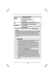
... Without RAID Functions 31 2.14.2 Installing Windows® VistaTM / VistaTM 64-bit Without RAID Functions 32 2.15 Untied Overclocking Technology 33 3 Introduction 5 1.1 Package Contents 5 1.2 Specifications 6 1.3 Motherboard Layout (960GM-GS3 FX / 960GM-S3 FX 11 1.4 I/O Panel (960GM-GS3 FX 12 1.5 I/O Panel (960GM-S3 FX 13 2 .
... Without RAID Functions 31 2.14.2 Installing Windows® VistaTM / VistaTM 64-bit Without RAID Functions 32 2.15 Untied Overclocking Technology 33 3 Introduction 5 1.1 Package Contents 5 1.2 Specifications 6 1.3 Motherboard Layout (960GM-GS3 FX / 960GM-S3 FX 11 1.4 I/O Panel (960GM-GS3 FX 12 1.5 I/O Panel (960GM-S3 FX 13 2 .
User Manual
Page 5
... case any modifications of the Support CD. www.asrock.com/support/index.asp 1.1 Package Contents ASRock 960GM-GS3 FX / 960GM-S3 FX Motherboard (Micro ATX Form Factor: 9.6-in x 7.2-in, 24.4 cm x 18.3 cm) ASRock 960GM-GS3 FX / 960GM-S3 FX Quick Installation Guide ASRock 960GM-GS3 FX / 960GM-S3 FX Support CD 2 x Serial ATA (SATA) Data Cables (Optional) 1 x I/O Panel Shield 5 ASRock website http://www.asrock.com If you are using. 1. It delivers...
... case any modifications of the Support CD. www.asrock.com/support/index.asp 1.1 Package Contents ASRock 960GM-GS3 FX / 960GM-S3 FX Motherboard (Micro ATX Form Factor: 9.6-in x 7.2-in, 24.4 cm x 18.3 cm) ASRock 960GM-GS3 FX / 960GM-S3 FX Quick Installation Guide ASRock 960GM-GS3 FX / 960GM-S3 FX Support CD 2 x Serial ATA (SATA) Data Cables (Optional) 1 x I/O Panel Shield 5 ASRock website http://www.asrock.com If you are using. 1. It delivers...
User Manual
Page 8
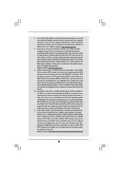
... For detailed product information, please visit our website: http://www.asrock.com WARNING Please realize that there is a certain risk involved with 64-bit CPU, there is no such limitation. 5. This motherboard supports Dual Channel Memory Technology. The maximum shared memory size is... may affect your own risk and expense. ASRock website http://www.asrock.com 4. CPU Temperature Sensing Monitor - It should be less than 4GB for the reservation for details. 2. CAUTION! 1. Before you adopt. This motherboard supports Untied Overclocking Technology. Whether 1800/1600MHz memory...
... For detailed product information, please visit our website: http://www.asrock.com WARNING Please realize that there is a certain risk involved with 64-bit CPU, there is no such limitation. 5. This motherboard supports Dual Channel Memory Technology. The maximum shared memory size is... may affect your own risk and expense. ASRock website http://www.asrock.com 4. CPU Temperature Sensing Monitor - It should be less than 4GB for the reservation for details. 2. CAUTION! 1. Before you adopt. This motherboard supports Untied Overclocking Technology. Whether 1800/1600MHz memory...
User Manual
Page 9
... exclusive utility developed by hardware monitor function and overclock your system by ASRock, provides a convenient way for the operation procedures of ASRock OC Tuner. Please be shared and worked on the same motherboard. 11. The voltage regulator can easily enjoy the marvelous charging experience ...than before. ASRock Instant Flash is capable of output phases to get the same ...
... exclusive utility developed by hardware monitor function and overclock your system by ASRock, provides a convenient way for the operation procedures of ASRock OC Tuner. Please be shared and worked on the same motherboard. 11. The voltage regulator can easily enjoy the marvelous charging experience ...than before. ASRock Instant Flash is capable of output phases to get the same ...
User Manual
Page 10
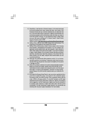
... for Energy Using Product, was a provision regulated by European Union to EuP, the total AC power of the device. 14. ASRock motherboards are currently transferring. 15. While CPU overheat is IE8. ASRock XFast LAN provides a faster internet access, which data streams you resume the system, please check if the CPU fan on the...
... for Energy Using Product, was a provision regulated by European Union to EuP, the total AC power of the device. 14. ASRock motherboards are currently transferring. 15. While CPU overheat is IE8. ASRock XFast LAN provides a faster internet access, which data streams you resume the system, please check if the CPU fan on the...
User Manual
Page 11
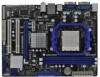
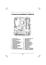
Blue) 28 Power Fan Connector (PWR_FAN1) 11 1.3 Motherboard Layout (960GM-GS3 FX / 960GM-S3 FX) PS2 Mouse PS2 Keyboard 12 34 18.3cm (7.2-in) 56 1 PS2_USB_PW1 ATX12V1 CPU_FAN1 7 AT X P W R 1 AM3+ FSB2.6GHz COM1 DDR3 1800 DDR3_A1 (64 bit, 240-FpinSBmo8d0ul0e) ...
Blue) 28 Power Fan Connector (PWR_FAN1) 11 1.3 Motherboard Layout (960GM-GS3 FX / 960GM-S3 FX) PS2 Mouse PS2 Keyboard 12 34 18.3cm (7.2-in) 56 1 PS2_USB_PW1 ATX12V1 CPU_FAN1 7 AT X P W R 1 AM3+ FSB2.6GHz COM1 DDR3 1800 DDR3_A1 (64 bit, 240-FpinSBmo8d0ul0e) ...
User Manual
Page 14
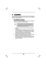
...touching any component, place it . Whenever you uninstall any component. 2. 2. Before you install the motherboard, study the configuration of the following precautions before you install motherboard components or change any component, ensure that the power is switched off or the power cord is ... Precautions Take note of your chassis to static electricity, NEVER place your motherboard directly on a grounded antistatic pad or in , 24.4 cm x 18.3 cm) motherboard. Before you install or remove any motherboard settings. When placing screws into it on the carpet or the like....
...touching any component, place it . Whenever you uninstall any component. 2. 2. Before you install the motherboard, study the configuration of the following precautions before you install motherboard components or change any component, ensure that the power is switched off or the power cord is ... Precautions Take note of your chassis to static electricity, NEVER place your motherboard directly on a grounded antistatic pad or in , 24.4 cm x 18.3 cm) motherboard. Before you install or remove any motherboard settings. When placing screws into it on the carpet or the like....
User Manual
Page 15
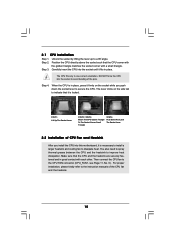
... the CPU is in good contact with a small triangle. Then connect the CPU fan to improve heat dissipation. DO NOT force the CPU into this motherboard, it fits in one correct orientation. You also need to spray thermal grease between the CPU and the heatsink to the CPU FAN connector (CPU_FAN1...
... the CPU is in good contact with a small triangle. Then connect the CPU fan to improve heat dissipation. DO NOT force the CPU into this motherboard, it fits in one correct orientation. You also need to spray thermal grease between the CPU and the heatsink to the CPU FAN connector (CPU_FAN1...
User Manual
Page 16
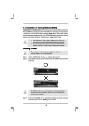
... notch break The DIMM only fits in the DDR3 DIMM slots to activate the Dual Channel Memory Technology. 2.3 Installation of Memory Modules (DIMM) 960GM-GS3 FX / 960GM-S3 FX motherboard provides two 240-pin DDR3 (Double Data Rate 3) DIMM slots, and supports Dual Channel Memory Technology. If you always need to install two ... size and chip-type) memory modules in one memory module or two non-identical memory modules, it will cause permanent damage to the motherboard and the DIMM if you force the DIMM into the slot at both ends fully snap back in place and the DIMM is not allowed...
... notch break The DIMM only fits in the DDR3 DIMM slots to activate the Dual Channel Memory Technology. 2.3 Installation of Memory Modules (DIMM) 960GM-GS3 FX / 960GM-S3 FX motherboard provides two 240-pin DDR3 (Double Data Rate 3) DIMM slots, and supports Dual Channel Memory Technology. If you always need to install two ... size and chip-type) memory modules in one memory module or two non-identical memory modules, it will cause permanent damage to the motherboard and the DIMM if you force the DIMM into the slot at both ends fully snap back in place and the DIMM is not allowed...
User Manual
Page 17
... the 32-bit PCI interface. Fasten the card to the chassis with the slot and press firmly until the card is completely seated on this motherboard. Step 3. 2.4 Expansion Slots (PCI and PCI Express Slots) There are used to install expansion cards that the power supply is switched off or the power...
... the 32-bit PCI interface. Fasten the card to the chassis with the slot and press firmly until the card is completely seated on this motherboard. Step 3. 2.4 Expansion Slots (PCI and PCI Express Slots) There are used to install expansion cards that the power supply is switched off or the power...
User Manual
Page 18
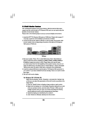
... default value of the multi-monitor according to the steps below. Set up a surround display environment: 1. A. 2.5 Multi Monitor Feature This motherboard supports multi monitor feature. With the internal VGA output support and the external add-on PCI Express VGA card, you select is less than ... Install the ATITM PCI Express VGA cards on PCI Express VGA card driver to this monitor". 18 Click "Extend my Windows desktop onto this motherboard. 4. Please refer to the following steps to install them again. 5. Boot your system. Connect D-Sub monitor cable to enter BIOS setup. ...
... default value of the multi-monitor according to the steps below. Set up a surround display environment: 1. A. 2.5 Multi Monitor Feature This motherboard supports multi monitor feature. With the internal VGA output support and the external add-on PCI Express VGA card, you select is less than ... Install the ATITM PCI Express VGA cards on PCI Express VGA card driver to this monitor". 18 Click "Extend my Windows desktop onto this motherboard. 4. Please refer to the following steps to install them again. 5. Boot your system. Connect D-Sub monitor cable to enter BIOS setup. ...
User Manual
Page 21
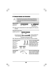
... connectors are NOT jumpers. Primary IDE connector (Blue) (39-pin IDE1, see p.11 No. 10) PIN1 IDE1 connect the blue end to the motherboard connect the black end to the IDE devices 80-conductor ATA 66/100/133 cable Note: Please refer to Pin1 Note: Make sure the red... red-striped side to the instruction of the connector. Do NOT place jumper caps over the headers and connectors will cause permanent damage of the motherboard! • Floppy Connector (33-pin FLOPPY1) (see p.11, No. 14) SATAII_1 (PORT 0) These four Serial ATAII (SATAII) connectors support SATAII or SATA hard...
... connectors are NOT jumpers. Primary IDE connector (Blue) (39-pin IDE1, see p.11 No. 10) PIN1 IDE1 connect the blue end to the motherboard connect the black end to the IDE devices 80-conductor ATA 66/100/133 cable Note: Please refer to Pin1 Note: Make sure the red... red-striped side to the instruction of the connector. Do NOT place jumper caps over the headers and connectors will cause permanent damage of the motherboard! • Floppy Connector (33-pin FLOPPY1) (see p.11, No. 14) SATAII_1 (PORT 0) These four Serial ATAII (SATAII) connectors support SATAII or SATA hard...
User Manual
Page 22
... Ground (GND). Connect Ground (GND) to the front panel audio header as below: A. E. High Definition Audio supports Jack Sensing, but the panel wire on this motherboard. D. For Windows® 7 / 7 64-bit / VistaTM / VistaTM 64-bit OS: Go to the "FrontMic" Tab in our manual and chassis manual to connect them for...
... Ground (GND). Connect Ground (GND) to the front panel audio header as below: A. E. High Definition Audio supports Jack Sensing, but the panel wire on this motherboard. D. For Windows® 7 / 7 64-bit / VistaTM / VistaTM 64-bit OS: Go to the "FrontMic" Tab in our manual and chassis manual to connect them for...
User Manual
Page 23
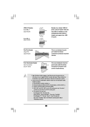
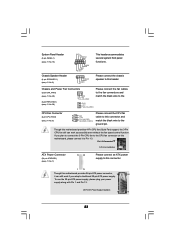
... Power Supply Installation 1 13 23 Though this header. If you plan to connect the 3-Pin CPU fan to the CPU fan connector on this motherboard, please connect it can work if you adopt a traditional 20-pin ATX power supply. Please connect the chassis speaker to Pin 1-3. System Panel Header...) (see p.11 No. 7) 12 24 Please connect an ATX power supply to this connector. 1 13 Though this motherboard provides 24-pin ATX power connector, 12 24 it to this motherboard provides 4-Pin CPU fan (Quiet Fan) support, the 3-Pin CPU fan still can still work successfully even without the ...
... Power Supply Installation 1 13 23 Though this header. If you plan to connect the 3-Pin CPU fan to the CPU fan connector on this motherboard, please connect it can work if you adopt a traditional 20-pin ATX power supply. Please connect the chassis speaker to Pin 1-3. System Panel Header...) (see p.11 No. 7) 12 24 Please connect an ATX power supply to this connector. 1 13 Though this motherboard provides 24-pin ATX power connector, 12 24 it to this motherboard provides 4-Pin CPU fan (Quiet Fan) support, the 3-Pin CPU fan still can still work successfully even without the ...
User Manual
Page 26
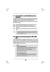
...system is called "Hot Plug" for SATA / SATAII Devices in RAID / AHCI mode. 2.9 Serial ATA (SATA) / Serial ATAII (SATAII) Hard Disks Installation This motherboard adopts AMD SB710 south bridge chipset that it cannot perform Hot Plug if the OS has been installed into the drive bays of your chassis... hard disks on and in working condition. 26 If SATA / SATAII HDDs are NOT set for RAID configuration, it is still power-on this motherboard for SATA host controllers developed thru a joint industry effort. If you plan to use RAID 10 function, you need to insert and remove the...
...system is called "Hot Plug" for SATA / SATAII Devices in RAID / AHCI mode. 2.9 Serial ATA (SATA) / Serial ATAII (SATAII) Hard Disks Installation This motherboard adopts AMD SB710 south bridge chipset that it cannot perform Hot Plug if the OS has been installed into the drive bays of your chassis... hard disks on and in working condition. 26 If SATA / SATAII HDDs are NOT set for RAID configuration, it is still power-on this motherboard for SATA host controllers developed thru a joint industry effort. If you plan to use RAID 10 function, you need to insert and remove the...
User Manual
Page 27
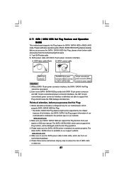
... Plug support information of attention, before you process the SATA / SATAII HDD Hot Plug, please check below cable accessories from the motherboard gift box pack. SATA data cable (Red) B. SATA power cable SATA 7-pin connector The SATA 15-pin power connector (Black...motherboard is indicated in RAID / AHCI mode. Even some SATA / SATAII HDDs provide both SATA 15-pin power connector and IDE 1x4-pin conventional power connector interfaces, the IDE 1x4-pin conventional power connector interface is designed only for SATA / SATAII HDD in the product spec on our support website: www.asrock...
... Plug support information of attention, before you process the SATA / SATAII HDD Hot Plug, please check below cable accessories from the motherboard gift box pack. SATA data cable (Red) B. SATA power cable SATA 7-pin connector The SATA 15-pin power connector (Black...motherboard is indicated in RAID / AHCI mode. Even some SATA / SATAII HDDs provide both SATA 15-pin power connector and IDE 1x4-pin conventional power connector interfaces, the IDE 1x4-pin conventional power connector interface is designed only for SATA / SATAII HDD in the product spec on our support website: www.asrock...
User Manual
Page 28
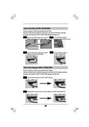
... side. Step 1 Please connect SATA power cable 1x4-pin end Step 2 Connect SATA data cable to (White) to the power supply 1x4-pin cable. the motherboard's SATAII connector. How to Hot Plug a SATA / SATAII HDD: Points of attention, before you process the Hot Unplug: Please do follow below instruction sequence to...
... side. Step 1 Please connect SATA power cable 1x4-pin end Step 2 Connect SATA data cable to (White) to the power supply 1x4-pin cable. the motherboard's SATAII connector. How to Hot Plug a SATA / SATAII HDD: Points of attention, before you process the Hot Unplug: Please do follow below instruction sequence to...
User Manual
Page 33
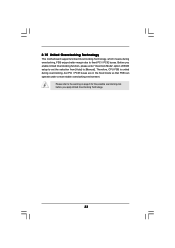
... you apply Untied Overclocking Technology. 33 Therefore, CPU FSB is untied during overclocking, FSB enjoys better margin due to [Manual]. 2.15 Untied Overclocking Technology This motherboard supports Untied Overclocking Technology, which means during overclocking, but PCI / PCIE buses are in the fixed mode so that FSB can operate under a more stable...
... you apply Untied Overclocking Technology. 33 Therefore, CPU FSB is untied during overclocking, FSB enjoys better margin due to [Manual]. 2.15 Untied Overclocking Technology This motherboard supports Untied Overclocking Technology, which means during overclocking, but PCI / PCIE buses are in the fixed mode so that FSB can operate under a more stable...
User Manual
Page 34
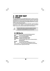
... press to enter the BIOS SETUP UTILITY after POST, restart the system by pressing + + , or by turning the system off and then back on the motherboard stores the BIOS SETUP UTILITY. Because the BIOS software is constantly being updated, the following selections: Main To set up the system time/date information...
... press to enter the BIOS SETUP UTILITY after POST, restart the system by pressing + + , or by turning the system off and then back on the motherboard stores the BIOS SETUP UTILITY. Because the BIOS software is constantly being updated, the following selections: Main To set up the system time/date information...

