
User Manual
Page 3
...Configuration 31 3.3.8 USB Configuration 33 3.4 Hardware Health Event Monitoring Screen 33 3.5 Boot Screen 34 3.5.1 Boot Settings Configuration 34 3.6 Security Screen 34 3.7 Exit Screen 35 3 Installation 10 Pre-installation Precautions 10 2.1 CPU Installation 11 2.2 Installation of CPU Fan and Heatsink 11 2.3 Installation of Memory Modules (DIMM 12 2.4 Expansion Slots (PCI and PCIE Slots 13 2.5 Jumpers Setup 15 2.6 Onboard Headers and Connectors 16 2.7 Serial ATA (SATA) Hard Disks Installation 19 2.8 Hot Plug Function for SATA HDDs 19 2.9 Making a SATA Driver Diskette For SATA...
...Configuration 31 3.3.8 USB Configuration 33 3.4 Hardware Health Event Monitoring Screen 33 3.5 Boot Screen 34 3.5.1 Boot Settings Configuration 34 3.6 Security Screen 34 3.7 Exit Screen 35 3 Installation 10 Pre-installation Precautions 10 2.1 CPU Installation 11 2.2 Installation of CPU Fan and Heatsink 11 2.3 Installation of Memory Modules (DIMM 12 2.4 Expansion Slots (PCI and PCIE Slots 13 2.5 Jumpers Setup 15 2.6 Onboard Headers and Connectors 16 2.7 Serial ATA (SATA) Hard Disks Installation 19 2.8 Hot Plug Function for SATA HDDs 19 2.9 Making a SATA Driver Diskette For SATA...

User Manual
Page 6
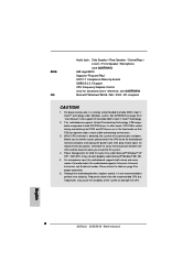
...Bridge: SiS 756 Chipset FSB @ 1 GHz (2.0 GT/s) / 800MHz Supports Untied Overclocking Technology (see CAUTION 3) CPU Fan Tachometer Chassis Fan Tachometer Voltage Monitoring: +12V, +5V, +3.3V, Vcore PCI Slots: 2 x PCI Slots, PCI Specification 2.2 PCI EXPRESS Slots: 1 slot with PCIE x 1, 1 slot with PCIE x 16; PCIE Specification 1.0a USB 2.0: 8 USB 2.0 Ports: 4 Ready-to-Use USB 2.0 Ports on the I/O Panel Plus 2 On-Board Headers Supporting 4 Extra USB 2.0 Ports (see CAUTION 4) ASRock 8CH I/O: 1 PS/2 Mouse Port, 1 PS/2 Keyboard Port 1 Serial Port: COM1 1 Parallel Port (ECP/EPP...
...Bridge: SiS 756 Chipset FSB @ 1 GHz (2.0 GT/s) / 800MHz Supports Untied Overclocking Technology (see CAUTION 3) CPU Fan Tachometer Chassis Fan Tachometer Voltage Monitoring: +12V, +5V, +3.3V, Vcore PCI Slots: 2 x PCI Slots, PCI Specification 2.2 PCI EXPRESS Slots: 1 slot with PCIE x 1, 1 slot with PCIE x 16; PCIE Specification 1.0a USB 2.0: 8 USB 2.0 Ports: 4 Ready-to-Use USB 2.0 Ports on the I/O Panel Plus 2 On-Board Headers Supporting 4 Extra USB 2.0 Ports (see CAUTION 4) ASRock 8CH I/O: 1 PS/2 Mouse Port, 1 PS/2 Keyboard Port 1 Serial Port: COM1 1 Parallel Port (ECP/EPP...

User Manual
Page 7
... to enable AMD's Cool 'n' QuietTM technology. 2. Please check the table on page 37 to fixed PCI/PCIE buses. In other than the recommended CPU bus frequencies may not work properly under Microsoft® Windows® XP SP1 / 2000 SP4. BIOS: OS: Audio Jack: Side Speaker / Rear Speaker / Central/Bass / Line In / Front Speaker / Microphone (see CAUTION 5) AMI Legal BIOS Supports "Plug and Play" ACPI 1.1 Compliance Wake Up Events SMBIOS 2.3.1 Support CPU Frequency Stepless Control...
... to enable AMD's Cool 'n' QuietTM technology. 2. Please check the table on page 37 to fixed PCI/PCIE buses. In other than the recommended CPU bus frequencies may not work properly under Microsoft® Windows® XP SP1 / 2000 SP4. BIOS: OS: Audio Jack: Side Speaker / Rear Speaker / Central/Bass / Line In / Front Speaker / Microphone (see CAUTION 5) AMI Legal BIOS Supports "Plug and Play" ACPI 1.1 Compliance Wake Up Events SMBIOS 2.3.1 Support CPU Frequency Stepless Control...

User Manual
Page 24
... default value for reference. BIOS SETUP UTILITY Advanced CPU Configuration Overclock Mode CPU Frequency (MHz) PCIE Frequency (MHz) Boot Failure Guard Spread Spectrum Cool' n' Quiet Processor Maximum Multiplier Processor Maximum Voltage Multiplier/Voltage Change Processor Multiplier Processor Voltage [Auto] [200] [100] [Enabled] [Auto] [Enabled] x11 1.550 V [Manual] [x8] [1.500V] Memory Clock Flexibility Option Burst Length CAS Latency (CL) TRCD [Auto] [Disabled] [8 Beats] [Auto] [Auto] If AUTO, multiplier and voltage will be set to [Manual], you may adjust the value of Boot Failure...
... default value for reference. BIOS SETUP UTILITY Advanced CPU Configuration Overclock Mode CPU Frequency (MHz) PCIE Frequency (MHz) Boot Failure Guard Spread Spectrum Cool' n' Quiet Processor Maximum Multiplier Processor Maximum Voltage Multiplier/Voltage Change Processor Multiplier Processor Voltage [Auto] [200] [100] [Enabled] [Auto] [Enabled] x11 1.550 V [Manual] [x8] [1.500V] Memory Clock Flexibility Option Burst Length CAS Latency (CL) TRCD [Auto] [Disabled] [8 Beats] [Auto] [Auto] If AUTO, multiplier and voltage will be set to [Manual], you may adjust the value of Boot Failure...

User Manual
Page 26
... Graphics Adapter This item will switch the PCI Bus scanning order while searching for the onboard AC97 Audio feature. HT Width You may set the HyperTransport width as [Auto], [200 MHz], [800 MHz], or [1000 MHz]. DRAM Voltage Use this to select the type of Primary VGA in case of multiple video controllers. Configuration options: [Auto], [High], [Normal], and [Low]. The default value is [Auto]. The default value is [Auto]. 3.3.3 ACPI Configuration Advanced BIOS SETUP UTILITY ACPI Settings Suspend To RAM Repost Video...
... Graphics Adapter This item will switch the PCI Bus scanning order while searching for the onboard AC97 Audio feature. HT Width You may set the HyperTransport width as [Auto], [200 MHz], [800 MHz], or [1000 MHz]. DRAM Voltage Use this to select the type of Primary VGA in case of multiple video controllers. Configuration options: [Auto], [High], [Normal], and [Low]. The default value is [Auto]. The default value is [Auto]. 3.3.3 ACPI Configuration Advanced BIOS SETUP UTILITY ACPI Settings Suspend To RAM Repost Video...
User Manual
Page 27
.... 3.3.4 IDE Configuration Advanced BIOS SETUP UTILITY IDE Configuration OnBoard IDE Controller OnBoard SATA Controller SATA Operation Mode Primary IDE Master Primary IDE Slave Secondary IDE Master Secondary IDE Slave SATA1 SATA2 [Both] [Enabled] [RAID] [Hard Disk] [Not Detected] [ATAPI CDROM] [Not Detected] [Not Detected] [Not Detected] DISABLED: disables the integrated IDE Controller. RTC Alarm Power On Use this item to enable or disable PCI devices to turn on the system from the power-soft-off mode. If you set the power state after an unexpected AC/power loss. PS/2 Keyboard Power...
.... 3.3.4 IDE Configuration Advanced BIOS SETUP UTILITY IDE Configuration OnBoard IDE Controller OnBoard SATA Controller SATA Operation Mode Primary IDE Master Primary IDE Slave Secondary IDE Master Secondary IDE Slave SATA1 SATA2 [Both] [Enabled] [RAID] [Hard Disk] [Not Detected] [ATAPI CDROM] [Not Detected] [Not Detected] [Not Detected] DISABLED: disables the integrated IDE Controller. RTC Alarm Power On Use this item to enable or disable PCI devices to turn on the system from the power-soft-off mode. If you set the power state after an unexpected AC/power loss. PS/2 Keyboard Power...

User Manual
Page 28
... to install Windows 98 SE / ME without RAID functions, please still select [RAID]. Use this option is [IDE]. OnBoard IDE Controller You may set the IDE configuration for the device that you plug PCIE-SATA2 card to this motherboard, the IDE Configuration screen will be applied to the configurations of "Primary IDE Slave", "Secondary IDE Master", and "Secondary IDE Slave" as below. Configuration options: [IDE], and [SATA]. 28 Configuration options: [Disabled], [Primary], [Secondary], [Both]. PRIMARY: enables only the Primary IDE Controller. BOTH: enables both . IDE Device...
... to install Windows 98 SE / ME without RAID functions, please still select [RAID]. Use this option is [IDE]. OnBoard IDE Controller You may set the IDE configuration for the device that you plug PCIE-SATA2 card to this motherboard, the IDE Configuration screen will be applied to the configurations of "Primary IDE Slave", "Secondary IDE Master", and "Secondary IDE Slave" as below. Configuration options: [IDE], and [SATA]. 28 Configuration options: [Disabled], [Primary], [Secondary], [Both]. PRIMARY: enables only the Primary IDE Controller. BOTH: enables both . IDE Device...

User Manual
Page 30
... PCI expansion cards' specifications require other settings. It is 32. Configuration options: [Disabled], [Auto], [Enabled]. 32-Bit Data Transfer Use this section, you may cause the system to malfunction. Setting wrong values in units of PCI clocks for PCI device latency timer register. BIOS SETUP UTILITY Advanced Floppy Configuration Floppy A Floppy B [1.44 MB 312"] [Disabled] Select the type of your floppy drive. Use this section may configure the type of floppy drive connected to enable or disable the S.M.A.R.T. (Self-Monitoring, Analysis, and Reporting Technology...
... PCI expansion cards' specifications require other settings. It is 32. Configuration options: [Disabled], [Auto], [Enabled]. 32-Bit Data Transfer Use this section, you may cause the system to malfunction. Setting wrong values in units of PCI clocks for PCI device latency timer register. BIOS SETUP UTILITY Advanced Floppy Configuration Floppy A Floppy B [1.44 MB 312"] [Disabled] Select the type of your floppy drive. Use this section may configure the type of floppy drive connected to enable or disable the S.M.A.R.T. (Self-Monitoring, Analysis, and Reporting Technology...

User Manual
Page 31
... Super IO Configuration Advanced BIOS SETUP UTILITY Configure Super IO Chipset OnBoard Floppy Controller Serial Port Address Infrared Port Address Parallel Port Address Parallel Port Mode EPP Version ECP Mode DMA Channel Parallel Port IRQ OnBoard Game Port OnBoard MIDI Port [Enabled] [3F8 / IRQ4] [Disabled] [378] [ECP + EPP] [1.9] [DMA3] [IRQ7] [Enabled] [Disabled] Allow BIOS to enable or disable floppy drive controller. If this item to set to set the address for the onboard parallel port or disable it . EPP Version Use this option is [ECP+EPP]. Infrared Port Address Use this...
... Super IO Configuration Advanced BIOS SETUP UTILITY Configure Super IO Chipset OnBoard Floppy Controller Serial Port Address Infrared Port Address Parallel Port Address Parallel Port Mode EPP Version ECP Mode DMA Channel Parallel Port IRQ OnBoard Game Port OnBoard MIDI Port [Enabled] [3F8 / IRQ4] [Disabled] [378] [ECP + EPP] [1.9] [DMA3] [IRQ7] [Enabled] [Disabled] Allow BIOS to enable or disable floppy drive controller. If this item to set to set the address for the onboard parallel port or disable it . EPP Version Use this option is [ECP+EPP]. Infrared Port Address Use this...

User Manual
Page 32
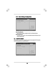
... USB Configuration BIOS SETUP UTILITY Advanced USB Configuration USB Controller USB 2.0 Support Legacy USB Support [Enabled] [Enabled] [Disabled] To enable or disable the onboard USB controllers. +F1 F9 F10 ESC Select Screen Select Item Change Option General Help Load Defaults Save and Exit Exit v02.54 (C) Copyright 1985-2003, American Megatrends, Inc. USB Controller Use this item to enable or disable the use of USB controller. etc. Or you may select [Auto] so that the system will disable the legacy USB support. 32 USB 2.0 Support Use this item to enable or disable the USB...
... USB Configuration BIOS SETUP UTILITY Advanced USB Configuration USB Controller USB 2.0 Support Legacy USB Support [Enabled] [Enabled] [Disabled] To enable or disable the onboard USB controllers. +F1 F9 F10 ESC Select Screen Select Item Change Option General Help Load Defaults Save and Exit Exit v02.54 (C) Copyright 1985-2003, American Megatrends, Inc. USB Controller Use this item to enable or disable the use of USB controller. etc. Or you may select [Auto] so that the system will disable the legacy USB support. 32 USB 2.0 Support Use this item to enable or disable the USB...
User Manual
Page 34
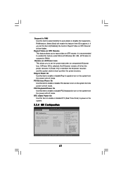
... Password : Not Installed Change Supervisor Password Change User Password Security Exit Install or Change the password. Boot From Network Use this item is set or change the supervisor/user password for the system. For the user password, you may set to enable or disable the Boot From Network feature. 3.5.1 Boot Settings Configuration BIOS SETUP UTILITY Boot Boot Settings Configuration Boot From Network Bootup Num-Lock [Disabled] [On] To enable or disable the boot from network feature. +F1 F9 F10 ESC Select Screen Select Item Change Option General Help Load Defaults...
... Password : Not Installed Change Supervisor Password Change User Password Security Exit Install or Change the password. Boot From Network Use this item is set or change the supervisor/user password for the system. For the user password, you may set to enable or disable the Boot From Network feature. 3.5.1 Boot Settings Configuration BIOS SETUP UTILITY Boot Boot Settings Configuration Boot From Network Bootup Num-Lock [Disabled] [On] To enable or disable the boot from network feature. +F1 F9 F10 ESC Select Screen Select Item Change Option General Help Load Defaults...

User Manual
Page 36
... want to display the menus. 4.2.2 Drivers Menu The Drivers Menu shows the available devices drivers including ASRock Express GbL PCI Express LAN card driver if the system detects the installed devices. The CD automatically displays the Main Menu if "AUTORUN" is enabled in the Support CD to know more information. 4.2 Support CD Information The Support CD that came with the motherboard contains necessary drivers and useful utilities that the motherboard supports. 4. If the Main Menu did not appear automatically, locate and double...
... want to display the menus. 4.2.2 Drivers Menu The Drivers Menu shows the available devices drivers including ASRock Express GbL PCI Express LAN card driver if the system detects the installed devices. The CD automatically displays the Main Menu if "AUTORUN" is enabled in the Support CD to know more information. 4.2 Support CD Information The Support CD that came with the motherboard contains necessary drivers and useful utilities that the motherboard supports. 4. If the Main Menu did not appear automatically, locate and double...
User Manual
Page 37
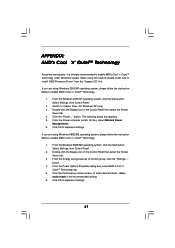
..., please follow the instruction below to enable AMD's Cool 'n' QuietTM technology: 1. Click the Performance combo list box, to implement settings. When using Windows 2000/XP operating system, please follow the instruction below to enable AMD's Cool 'n' QuietTM technology: 1. If you are using this feature, please make sure to enable AMD's Cool 'n' QuietTM technology under Windows system. Select Settings, then Control Panel. 2. button. button. 4. Automatic mode is strongly recommended to install "AMD Processor Driver" from the "Support CD" first...
..., please follow the instruction below to enable AMD's Cool 'n' QuietTM technology: 1. Click the Performance combo list box, to implement settings. When using Windows 2000/XP operating system, please follow the instruction below to enable AMD's Cool 'n' QuietTM technology: 1. If you are using this feature, please make sure to enable AMD's Cool 'n' QuietTM technology under Windows system. Select Settings, then Control Panel. 2. button. button. 4. Automatic mode is strongly recommended to install "AMD Processor Driver" from the "Support CD" first...

Quick Installation Guide
Page 2
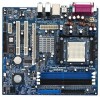
...) 14 Chassis Speaker Header (SPEAKER 1) 15 Chassis Fan Connector (CHA_FAN1) 16 USB 2.0 Header (USB67, Blue) 17 USB 2.0 Header (USB_H45, Blue) 18 Clear CMOS Jumper (CLRCMOS2) 19 Infrared Module Header (IR1) 20 Flash Memory 21 Floppy Connector (FLOPPY1) 22 Game Port Header (GAME1) 23 Front Panel Audio Header (AUDIO1) 24 JR1JL1 Jumper 25 PCI EXPRESS Slot (PCIE2) 26 PCI Slots (PCI1 - 2) 27 PCI EXPRESS Slot (PCIE1) 28 Internal Audio Connector: CD1 (Black) 29 ATX Power Connector (ATXPWR1) 30 CPU Fan Connector (CPU_FAN1) 2 ASRock 939S56-M Motherboard Blue) 6 2 x 184-pin DDR DIMM Slots (Dual Channel...
...) 14 Chassis Speaker Header (SPEAKER 1) 15 Chassis Fan Connector (CHA_FAN1) 16 USB 2.0 Header (USB67, Blue) 17 USB 2.0 Header (USB_H45, Blue) 18 Clear CMOS Jumper (CLRCMOS2) 19 Infrared Module Header (IR1) 20 Flash Memory 21 Floppy Connector (FLOPPY1) 22 Game Port Header (GAME1) 23 Front Panel Audio Header (AUDIO1) 24 JR1JL1 Jumper 25 PCI EXPRESS Slot (PCIE2) 26 PCI Slots (PCI1 - 2) 27 PCI EXPRESS Slot (PCIE1) 28 Internal Audio Connector: CD1 (Black) 29 ATX Power Connector (ATXPWR1) 30 CPU Fan Connector (CPU_FAN1) 2 ASRock 939S56-M Motherboard Blue) 6 2 x 184-pin DDR DIMM Slots (Dual Channel...
Quick Installation Guide
Page 6
... recommended CPU bus frequencies may not work properly under Windows system. For audio output, this motherboard supports both stereo and mono modes. Frequencies other words, CPU FSB is not recommended to enable AMD's Cool 'n' QuietTM technology under Microsoft® Windows® 98/ ME. 5. For power-saving sake, it is untied during overclocking, but PCIE and PCI buses are in the support CD to fixed PCI/PCIE buses. Although this motherboard offers stepless control, it...
... recommended CPU bus frequencies may not work properly under Windows system. For audio output, this motherboard supports both stereo and mono modes. Frequencies other words, CPU FSB is not recommended to enable AMD's Cool 'n' QuietTM technology under Microsoft® Windows® 98/ ME. 5. For power-saving sake, it is untied during overclocking, but PCIE and PCI buses are in the support CD to fixed PCI/PCIE buses. Although this motherboard offers stepless control, it...

Quick Installation Guide
Page 13
English 13 ASRock 939S56-M Motherboard Serial ATA (SATA) Power Cable (Optional) connect to the SATA HDD power connector connect to the power supply Please connect the black end of SATA power cable to the power connector on the rear panel. Infrared Module Header (5-pin IR1) (see p.2, No. 23) CD1 This connector allows you to -use USB 2.0 ports on the rear panel. USB 2.0 Header (9-pin USB_H45) (see p.2, No. 16) ASRock 8CH I /OTM provides you 4 ready-to receive stereo audio input from sound sources such as a CD-ROM, DVD-ROM, TV tuner...
English 13 ASRock 939S56-M Motherboard Serial ATA (SATA) Power Cable (Optional) connect to the SATA HDD power connector connect to the power supply Please connect the black end of SATA power cable to the power connector on the rear panel. Infrared Module Header (5-pin IR1) (see p.2, No. 23) CD1 This connector allows you to -use USB 2.0 ports on the rear panel. USB 2.0 Header (9-pin USB_H45) (see p.2, No. 16) ASRock 8CH I /OTM provides you 4 ready-to receive stereo audio input from sound sources such as a CD-ROM, DVD-ROM, TV tuner...

Quick Installation Guide
Page 17
... drivers and useful utilities that came with its various sub-menus and to display the menus. 17 ASRock 939S56-M Motherboard English 3. It is a menu-driven program, which allows you start up the computer, please press during the Power-On-Self-Test (POST) to enter BIOS Setup after POST, please restart the system by pressing + + , or pressing the reset button on the system chassis. The Support CD that will display the Main Menu...
... drivers and useful utilities that came with its various sub-menus and to display the menus. 17 ASRock 939S56-M Motherboard English 3. It is a menu-driven program, which allows you start up the computer, please press during the Power-On-Self-Test (POST) to enter BIOS Setup after POST, please restart the system by pressing + + , or pressing the reset button on the system chassis. The Support CD that will display the Main Menu...
RAID Installation Guide
Page 23
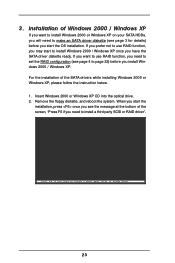
... instruction below. 1. 3. Installation of Windows 2000 / Windows XP If you want to use RAID function, you have the SATA driver diskette ready. For the installation of the screen, "Press F6 if you need to install a third party SCSI or RAID driver . . . 23 Remove the floppy diskette, and reboot the system. When you start the OS installation. If you want to install Windows 2000 or Windows XP on your SATA HDDs, you start the installation...
... instruction below. 1. 3. Installation of Windows 2000 / Windows XP If you want to use RAID function, you have the SATA driver diskette ready. For the installation of the screen, "Press F6 if you need to install a third party SCSI or RAID driver . . . 23 Remove the floppy diskette, and reboot the system. When you start the OS installation. If you want to install Windows 2000 or Windows XP on your SATA HDDs, you start the installation...
RAID Installation Guide
Page 24
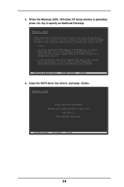
... RAID driver . . . 24 If you do not have any device support disks from a mass storage device manufacturer, press S. Insert the SATA driver into Drive A: Press ENTER when ready. To specify additional SCSI adapters, CD-ROM drives, or special disk controllers for use with Windows, including those for which you have a device support disk from a mass storage device manufacturer, or do not want to specify an Additional Device(s). 3. Windows Setup Please insert the disk labeled Manufacturer-supplied hardware support disk...
... RAID driver . . . 24 If you do not have any device support disks from a mass storage device manufacturer, press S. Insert the SATA driver into Drive A: Press ENTER when ready. To specify additional SCSI adapters, CD-ROM drives, or special disk controllers for use with Windows, including those for which you have a device support disk from a mass storage device manufacturer, or do not want to specify an Additional Device(s). 3. Windows Setup Please insert the disk labeled Manufacturer-supplied hardware support disk...

RAID Utility for Windows Guide
Page 22
... the right button of the two continual hot-plug actions must be installed automatically. It is ONLY applied to prevent intervention. 4. The Hot-Plug support is recommended to connect SATA HDDs to different power wires to Single SATA drive. 2. If you only hot-plug the SATA data cable without unplugging the power cable, sometimes it always be popup. You can click "Exit" to use SiS964/SiS180 Hot-Plug Utility 1. Time...
... the right button of the two continual hot-plug actions must be installed automatically. It is ONLY applied to prevent intervention. 4. The Hot-Plug support is recommended to connect SATA HDDs to different power wires to Single SATA drive. 2. If you only hot-plug the SATA data cable without unplugging the power cable, sometimes it always be popup. You can click "Exit" to use SiS964/SiS180 Hot-Plug Utility 1. Time...


