
User Manual
Page 1
All rights reserved. 1 939A790GMH User Manual Version 1.0 Published July 2010 Copyright©2009 ASRock INC.
All rights reserved. 1 939A790GMH User Manual Version 1.0 Published July 2010 Copyright©2009 ASRock INC.
User Manual
Page 2
..., transmitted, or translated in any interference received, including interference that may appear in this manual. CALIFORNIA, USA ONLY The Lithium battery adopted on this manual, ASRock does not provide warranty of any means, except duplication of documentation by ASRock. Disclaimer: Specifications and information contained in any form or by any kind, either expressed or...
..., transmitted, or translated in any interference received, including interference that may appear in this manual. CALIFORNIA, USA ONLY The Lithium battery adopted on this manual, ASRock does not provide warranty of any means, except duplication of documentation by ASRock. Disclaimer: Specifications and information contained in any form or by any kind, either expressed or...
User Manual
Page 5
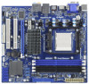
In case any modifications of this manual occur, the updated version will be available on ASRock website as well. www.asrock.com/support/index.asp 1.1 Package Contents ASRock 939A790GMH Motherboard (Micro ATX Form Factor: 9.6-in x 8.6-in, 24.4 cm x 21.8 cm) ASRock 939A790GMH Quick Installation Guide ASRock 939A790GMH Support CD 1 x Ultra ATA 66/100/133 IDE Ribbon Cable (80-conductor) 2 x Serial...
In case any modifications of this manual occur, the updated version will be available on ASRock website as well. www.asrock.com/support/index.asp 1.1 Package Contents ASRock 939A790GMH Motherboard (Micro ATX Form Factor: 9.6-in x 8.6-in, 24.4 cm x 21.8 cm) ASRock 939A790GMH Quick Installation Guide ASRock 939A790GMH Support CD 1 x Ultra ATA 66/100/133 IDE Ribbon Cable (80-conductor) 2 x Serial...
User Manual
Page 14
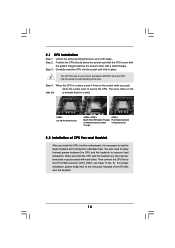
... 2.2 Installation of the CPU fan and the heatsink. 14 You also need to spray thermal grease between the CPU and the heatsink to the instruction manuals of CPU Fan and Heatsink After you push down the socket lever to dissipate heat. Make sure that the CPU corner with the golden triangle...
... 2.2 Installation of the CPU fan and the heatsink. 14 You also need to spray thermal grease between the CPU and the heatsink to the instruction manuals of CPU Fan and Heatsink After you push down the socket lever to dissipate heat. Make sure that the CPU corner with the golden triangle...
User Manual
Page 26
... voice through front mic, please deselect "Mute" icon in "Front Mic" of "Playback" portion. D. Connect Mic_IN (MIC) to the "Front Mic" Tab in our manual and chassis manual to make the Front Mic as below: A. G. Enter Advanced Settings, and then select Chipset Configuration. For Windows® 7 / 7 64-bit / VistaTM / VistaTM 64-bit...
... voice through front mic, please deselect "Mute" icon in "Front Mic" of "Playback" portion. D. Connect Mic_IN (MIC) to the "Front Mic" Tab in our manual and chassis manual to make the Front Mic as below: A. G. Enter Advanced Settings, and then select Chipset Configuration. For Windows® 7 / 7 64-bit / VistaTM / VistaTM 64-bit...

User Manual
Page 30
...motherboard is designed only for SATA / SATAII HDD in the product spec on our support website: www.asrock.com 4. Please make sure the SATA / SATAII driver is available on our website: www.asrock.com 2. 2.12 SATA / SATAII HDD Hot Plug Feature and Operation Guide This motherboard supports Hot ...SATAII HDD 1x4-pin conventional power connector (White) connect to support Hot Plug and will be processed. 2. Make sure your dealer or HDD user manual. The latest SATA / SATAII driver is installed into system properly. Make sure to reduce the risk of SATA / SATAII HDD Hot Plug feature carefully...
...motherboard is designed only for SATA / SATAII HDD in the product spec on our support website: www.asrock.com 4. Please make sure the SATA / SATAII driver is available on our website: www.asrock.com 2. 2.12 SATA / SATAII HDD Hot Plug Feature and Operation Guide This motherboard supports Hot ...SATAII HDD 1x4-pin conventional power connector (White) connect to support Hot Plug and will be processed. 2. Make sure your dealer or HDD user manual. The latest SATA / SATAII driver is installed into system properly. Make sure to reduce the risk of SATA / SATAII HDD Hot Plug feature carefully...

User Manual
Page 39
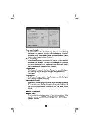
.... It should always be done at your CPU and motherboard. Select Screen Select Item Enter Go to select Overclock Mode. If it is set to [Manual], you can set to [Auto] by default. PCIE Frequency (MHz) Use this option to adjust CPU frequency. However, it is recommended to keep the default...
.... It should always be done at your CPU and motherboard. Select Screen Select Item Enter Go to select Overclock Mode. If it is set to [Manual], you can set to [Auto] by default. PCIE Frequency (MHz) Use this option to adjust CPU frequency. However, it is recommended to keep the default...
User Manual
Page 40
... it will show when "Multiplier/Voltage Change" is not recommended to adjust the value of this motherboard. otherwise, it is set to [Manual]; The range of this item to enable CPU internal thermal control mechanism to your own risk and expense. HT Bus Speed This feature allows...Processor Multiplier Processor Voltage HT Bus Speed HT Bus Width CPU Thermal Throttle Memory Configuration [Auto] [200] [100] [Auto] x12 2400 MHZ 1.400 V [Manual] [x12 2400 MHz] [1.350 V] [Auto] [Auto] [Auto] Overclocking may cause damage to keep the CPU from overheated. Select Screen Select Item Enter ...
... it will show when "Multiplier/Voltage Change" is not recommended to adjust the value of this motherboard. otherwise, it is set to [Manual]; The range of this item to enable CPU internal thermal control mechanism to your own risk and expense. HT Bus Speed This feature allows...Processor Multiplier Processor Voltage HT Bus Speed HT Bus Width CPU Thermal Throttle Memory Configuration [Auto] [200] [100] [Auto] x12 2400 MHZ 1.400 V [Manual] [x12 2400 MHz] [1.350 V] [Auto] [Auto] [Auto] Overclocking may cause damage to keep the CPU from overheated. Select Screen Select Item Enter ...

Quick Installation Guide
Page 4
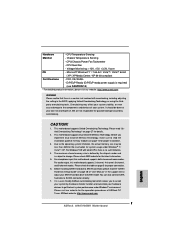
...ASRock's commitment to this manual will be available on ASRock website as well. You may find the latest VGA cards and CPU support lists on ASRock website without notice. Because the motherboard specifications and the BIOS software might be subject to the hardware installation. www.asrock.com/support/index.asp 1.1 Package Contents ASRock 939A790GMH... Motherboard (Micro ATX Form Factor: 9.6-in x 8.6-in, 24.4 cm x 21.8 cm) ASRock 939A790GMH Quick Installation Guide ASRock 939A790GMH Support CD 1...
...ASRock's commitment to this manual will be available on ASRock website as well. You may find the latest VGA cards and CPU support lists on ASRock website without notice. Because the motherboard specifications and the BIOS software might be subject to the hardware installation. www.asrock.com/support/index.asp 1.1 Package Contents ASRock 939A790GMH... Motherboard (Micro ATX Form Factor: 9.6-in x 8.6-in, 24.4 cm x 21.8 cm) ASRock 939A790GMH Quick Installation Guide ASRock 939A790GMH Support CD 1...
Quick Installation Guide
Page 7
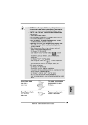
...ASRock overclocking tool which allows you implement Dual Channel Memory Technology, make sure to SATAII mode. CAUTION! 1. For Windows® OS with overclocking, including adjusting the setting in the support CD to adjust your SATAII hard disk drive to read the installation guide of "User Manual...supports Untied Overclocking Technology. For audio output, this motherboard supports both stereo and mono modes. ASRock website: http://www.asrock.com English 7 ASRock 939A790GMH Motherboard Please read the "SATAII Hard Disk Setup Guide" on page 27 for possible damage ...
...ASRock overclocking tool which allows you implement Dual Channel Memory Technology, make sure to SATAII mode. CAUTION! 1. For Windows® OS with overclocking, including adjusting the setting in the support CD to adjust your SATAII hard disk drive to read the installation guide of "User Manual...supports Untied Overclocking Technology. For audio output, this motherboard supports both stereo and mono modes. ASRock website: http://www.asrock.com English 7 ASRock 939A790GMH Motherboard Please read the "SATAII Hard Disk Setup Guide" on page 27 for possible damage ...
Quick Installation Guide
Page 11
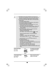
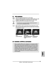
...Fan and Heatsink After you push down the socket lever to improve heat dissipation. Then connect the CPU fan to a 90o angle. Step 3. English 11 ASRock 939A790GMH Motherboard Unlock the socket by lifting the lever up to the CPU FAN connector (CPU_FAN1, see Page 2, No. 5). Position the CPU directly above the... to spray thermal grease between the CPU and the heatsink to secure the CPU. Carefully insert the CPU into the socket to the instruction manuals of the pins. The CPU fits only in place. Make sure that the CPU corner with the golden triangle matches the socket corner with...
...Fan and Heatsink After you push down the socket lever to improve heat dissipation. Then connect the CPU fan to a 90o angle. Step 3. English 11 ASRock 939A790GMH Motherboard Unlock the socket by lifting the lever up to the CPU FAN connector (CPU_FAN1, see Page 2, No. 5). Position the CPU directly above the... to spray thermal grease between the CPU and the heatsink to secure the CPU. Carefully insert the CPU into the socket to the instruction manuals of the pins. The CPU fits only in place. Make sure that the CPU corner with the golden triangle matches the socket corner with...
Quick Installation Guide
Page 23
Please follow the instruction in our manual and chassis manual to Ground (GND). Connect Ground (GND) to install your voice through front mic, please deselect "Mute" icon in the Realtek Control panel. Set the Front Panel Control option from [Auto] to this header. 23 ASRock 939A790GMH Motherboard For Windows® VistaTM / VistaTM 64-bit OS...
Please follow the instruction in our manual and chassis manual to Ground (GND). Connect Ground (GND) to install your voice through front mic, please deselect "Mute" icon in the Realtek Control panel. Set the Front Panel Control option from [Auto] to this header. 23 ASRock 939A790GMH Motherboard For Windows® VistaTM / VistaTM 64-bit OS...
Quick Installation Guide
Page 28
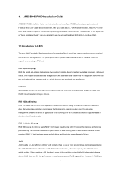
... "ASSETUP.EXE" from the "BIN" folder in the Support CD. 4. When you to display the menus. 28 ASRock 939A790GMH Motherboard English It is designed to enter BIOS Setup utility; 3. If you wish to the User Manual (PDF file) contained in the Support CD to scroll through its test routines. For the detailed information...
... "ASSETUP.EXE" from the "BIN" folder in the Support CD. 4. When you to display the menus. 28 ASRock 939A790GMH Motherboard English It is designed to enter BIOS Setup utility; 3. If you wish to the User Manual (PDF file) contained in the Support CD to scroll through its test routines. For the detailed information...
RAID Installation Guide
Page 2
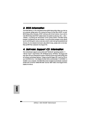
... called data mirroring that optimizes two identical hard disk drives to one drive to configure RAID functions by following the detailed instruction of the "User Manual" in our support CD or "Quick Installation Guide", then you can improve the access performance, it does not provide any HDDs of the RAID 0 Disk...
... called data mirroring that optimizes two identical hard disk drives to one drive to configure RAID functions by following the detailed instruction of the "User Manual" in our support CD or "Quick Installation Guide", then you can improve the access performance, it does not provide any HDDs of the RAID 0 Disk...
RAID Installation Guide
Page 8
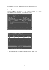
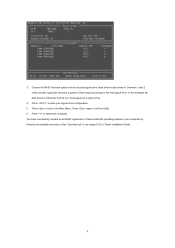
Then please follow the steps below. 1. The Define LD Menu displays again. 2. Enter the desired capacity (MB) for the first logical drive and press . Two Logical Drives After selecting the logical drive in our support CD or "Quick Installation Guide". Press the up and down arrow keys to the first logical drive. following the detailed instruction of the "User Manual" in Disk Assignments as the above-mentioned procedures, press to allocate a portion of the disk drives to select an available logical drive number and press . 8
Then please follow the steps below. 1. The Define LD Menu displays again. 2. Enter the desired capacity (MB) for the first logical drive and press . Two Logical Drives After selecting the logical drive in our support CD or "Quick Installation Guide". Press the up and down arrow keys to the first logical drive. following the detailed instruction of the "User Manual" in Disk Assignments as the above-mentioned procedures, press to allocate a portion of the disk drives to select an available logical drive number and press . 8
RAID Installation Guide
Page 9
... of their capacity belongs to exit the Utility. 6. In this example the disk drives in Channels 1 and 2 reflect smaller capacities because a portion of the "User Manual" in our support CD or "Quick Installation Guide". 9 Press to the Main Menu. Press again to the first logical drive.
... of their capacity belongs to exit the Utility. 6. In this example the disk drives in Channels 1 and 2 reflect smaller capacities because a portion of the "User Manual" in our support CD or "Quick Installation Guide". 9 Press to the Main Menu. Press again to the first logical drive.
RAID Installation Guide
Page 13
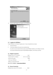
... Install Complete screen appears, click the Finish button. 2.4 Logging into RAIDXpert Choose RAIDXpert in the Windows Programs menu. 12. Launch the Browser. 2. Or, log on manually with your entry looks like this: http://127.0.0.1:25902/ati or http://localhost:25902/ati 2.6 Secure Connection RAIDXpert uses a secure HTTP connection https:// 13 In...
... Install Complete screen appears, click the Finish button. 2.4 Logging into RAIDXpert Choose RAIDXpert in the Windows Programs menu. 12. Launch the Browser. 2. Or, log on manually with your entry looks like this: http://127.0.0.1:25902/ati or http://localhost:25902/ati 2.6 Secure Connection RAIDXpert uses a secure HTTP connection https:// 13 In...
