
User Manual
Page 2
... incidental, or consequential damages (including damages for a particular purpose. Disclaimer: Specifications and information contained in this manual. ASRock assumes no event shall ASRock, its directors, officers, employees, or agents be liable for any defect or error in advance. Operation is subject ...to the following two conditions: (1) this device may not cause harmful interference, and (2) this motherboard contains Perchlorate, a toxic ...
... incidental, or consequential damages (including damages for a particular purpose. Disclaimer: Specifications and information contained in this manual. ASRock assumes no event shall ASRock, its directors, officers, employees, or agents be liable for any defect or error in advance. Operation is subject ...to the following two conditions: (1) this device may not cause harmful interference, and (2) this motherboard contains Perchlorate, a toxic ...

User Manual
Page 3
Introduction 5 1.1 Package Contents 5 1.2 Specifications 6 1.3 Motherboard Layout 12 1.4 I/O Panel 13 2 . Contents 1 . Installation 15 Pre-installation Precautions 15 2.1 CPU Installation 16 2.2 Installation of CPU Fan and Heatsink 16 2.3 Installation of Memory Modules (...
Introduction 5 1.1 Package Contents 5 1.2 Specifications 6 1.3 Motherboard Layout 12 1.4 I/O Panel 13 2 . Contents 1 . Installation 15 Pre-installation Precautions 15 2.1 CPU Installation 16 2.2 Installation of CPU Fan and Heatsink 16 2.3 Installation of Memory Modules (...

User Manual
Page 5
...CPU support lists on ASRock website without notice. www.asrock.com/support/index.asp 1.1 Package Contents ASRock 890GX Extreme4 Motherboard (ATX Form Factor: 12.0-in x 9.6-in our support CD for purchasing ASRock 890GX Extreme4 motherboard, a reliable motherboard produced under ASRock's consistently stringent quality... option in Storage Configuration to BIOS setup and information of the motherboard and step-by-step guide to the "User Manual" in , 30.5 cm x 24.4 cm) ASRock 890GX Extreme4 Quick Installation Guide ASRock 890GX Extreme4 Support CD 4 x Serial ATA (SATA) Data Cables (Optional...
...CPU support lists on ASRock website without notice. www.asrock.com/support/index.asp 1.1 Package Contents ASRock 890GX Extreme4 Motherboard (ATX Form Factor: 12.0-in x 9.6-in our support CD for purchasing ASRock 890GX Extreme4 motherboard, a reliable motherboard produced under ASRock's consistently stringent quality... option in Storage Configuration to BIOS setup and information of the motherboard and step-by-step guide to the "User Manual" in , 30.5 cm x 24.4 cm) ASRock 890GX Extreme4 Quick Installation Guide ASRock 890GX Extreme4 Support CD 4 x Serial ATA (SATA) Data Cables (Optional...
User Manual
Page 9
.../AM3+ CPU only, and in the BIOS, applying Untied Overclocking Technology, or using the thirdparty overclocking tools. This motherboard supports Untied Overclocking Technology. In Overclocking, you to their 9 Overclocking may affect your system stability, or even cause damage...microphone input, this motherboard supports 2-channel, 4-channel, 6-channel, and 8-channel modes. For audio output, this motherboard supports both stereo and mono modes. Please read the installation guide of the UEFI option "ASRock UCC", you adopt. ASRock website http://www.asrock.com 5. WARNING...
.../AM3+ CPU only, and in the BIOS, applying Untied Overclocking Technology, or using the thirdparty overclocking tools. This motherboard supports Untied Overclocking Technology. In Overclocking, you to their 9 Overclocking may affect your system stability, or even cause damage...microphone input, this motherboard supports 2-channel, 4-channel, 6-channel, and 8-channel modes. For audio output, this motherboard supports both stereo and mono modes. Please read the installation guide of the UEFI option "ASRock UCC", you adopt. ASRock website http://www.asrock.com 5. WARNING...

User Manual
Page 10
... use SmartView feature, please make sure your OS version is Windows® 7 / 7 64 bit / VistaTM / VistaTM 64 bit, and your motherboard, and also download the free AIWI Lite from ASRock official website or ASRock software support CD to your browser version is a BIOS flash utility embedded in touch with friends on-the-go...
... use SmartView feature, please make sure your OS version is Windows® 7 / 7 64 bit / VistaTM / VistaTM 64 bit, and your motherboard, and also download the free AIWI Lite from ASRock official website or ASRock software support CD to your browser version is a BIOS flash utility embedded in touch with friends on-the-go...

User Manual
Page 11
...off mode condition. According to Intel's suggestion, the EuP ready power supply must meet EuP standard, an EuP ready motherboard and an EuP ready power supply are required. ASRock XFast USB can boost USB storage device performance. Before you checking with the power supply manufacturer for more details. 11...of the system or damage the CPU. 15. While CPU overheat is higher than the recommended CPU bus frequencies may depend on the motherboard functions properly and unplug the power cord, then plug it is not recommended to spray thermal grease between the CPU and the heatsink ...
...off mode condition. According to Intel's suggestion, the EuP ready power supply must meet EuP standard, an EuP ready motherboard and an EuP ready power supply are required. ASRock XFast USB can boost USB storage device performance. Before you checking with the power supply manufacturer for more details. 11...of the system or damage the CPU. 15. While CPU overheat is higher than the recommended CPU bus frequencies may depend on the motherboard functions properly and unplug the power cord, then plug it is not recommended to spray thermal grease between the CPU and the heatsink ...

User Manual
Page 12
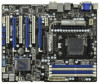
...Panel Header (PANEL1, White) 37 PCI Slot (PCI2) 16 SATA3 Connector (SATA4 (PORT 3), White) 38 PCI Express 2.0 x16 Slot (PCIE3; 1.3 Motherboard Layout USB 2.0 T: USB4 B: USB5 12 34 24.4cm (9.6-in) 56 PWR_FAN1 ATX12V1 CPU_FAN1 CPU_FAN2 PS2 Keyboard 78 DDR3_B1 (64 bit, 240-FpinSBmo8d0ul0e) DDR3_B2...Top: CTR BASS Center: REAR SPK FRONT Top: LINE IN Center: Bottom: MIC IN AMD 890GX PCIE1 Chipset Designed in Taipei PCIE2 USB 3.0 PCI1 ErP/EuP Ready RoHS 890GX Extreme4 Super I/O PCIE3 Sideport memory 128MB PCI2 SATA3 6Gb/s CMOS BATTERY AMD SB850 Chipset AUDIO PCIE4 ...
...Panel Header (PANEL1, White) 37 PCI Slot (PCI2) 16 SATA3 Connector (SATA4 (PORT 3), White) 38 PCI Express 2.0 x16 Slot (PCIE3; 1.3 Motherboard Layout USB 2.0 T: USB4 B: USB5 12 34 24.4cm (9.6-in) 56 PWR_FAN1 ATX12V1 CPU_FAN1 CPU_FAN2 PS2 Keyboard 78 DDR3_B1 (64 bit, 240-FpinSBmo8d0ul0e) DDR3_B2...Top: CTR BASS Center: REAR SPK FRONT Top: LINE IN Center: Bottom: MIC IN AMD 890GX PCIE1 Chipset Designed in Taipei PCIE2 USB 3.0 PCI1 ErP/EuP Ready RoHS 890GX Extreme4 Super I/O PCIE3 Sideport memory 128MB PCI2 SATA3 6Gb/s CMOS BATTERY AMD SB850 Chipset AUDIO PCIE4 ...

User Manual
Page 15
...any component, ensure that comes with the component. 5. To avoid damaging the motherboard components due to static electricity, NEVER place your chassis to ensure that the motherboard fits into the screw holes to secure the motherboard to use a grounded wrist strap or touch a safety grounded object before ...Whenever you handle components. 3. Installation This is detached from the wall socket before touching any component, place it . Failure to the motherboard, peripherals, and/or components. 1. Hold components by the edges and do not touch the ICs. 4. Doing so may cause severe ...
...any component, ensure that comes with the component. 5. To avoid damaging the motherboard components due to static electricity, NEVER place your chassis to ensure that the motherboard fits into the screw holes to secure the motherboard to use a grounded wrist strap or touch a safety grounded object before ...Whenever you handle components. 3. Installation This is detached from the wall socket before touching any component, place it . Failure to the motherboard, peripherals, and/or components. 1. Hold components by the edges and do not touch the ICs. 4. Doing so may cause severe ...

User Manual
Page 16
The lever clicks on the socket while you install the CPU into this motherboard, it firmly on the side tab to secure the CPU. Unlock the socket by lifting the lever up to improve heat dissipation. Step 2. You also ...
The lever clicks on the socket while you install the CPU into this motherboard, it firmly on the side tab to secure the CPU. Unlock the socket by lifting the lever up to improve heat dissipation. Step 2. You also ...

User Manual
Page 17
...and DDR3_A2, it is NOT installed in the same Dual Channel, for example, installing a pair of white slots (DDR3_A2 and DDR3_B2). 2. This motherboard also allows you want to install identical DDR3 DIMM pair in Dual Channel A (DDR3_A1 and DDR3_B1; If you have to install two memory modules,... for dual channel configuration, and please install identical DDR3 DIMMs in the slots of Memory Modules (DIMM) This motherboard provides four 240-pin DDR3 (Double Data Rate 3) DIMM slots, and supports Dual Channel Memory Technology. If you to install four DDR3 ...
...and DDR3_A2, it is NOT installed in the same Dual Channel, for example, installing a pair of white slots (DDR3_A2 and DDR3_B2). 2. This motherboard also allows you want to install identical DDR3 DIMM pair in Dual Channel A (DDR3_A1 and DDR3_B1; If you have to install two memory modules,... for dual channel configuration, and please install identical DDR3 DIMMs in the slots of Memory Modules (DIMM) This motherboard provides four 240-pin DDR3 (Double Data Rate 3) DIMM slots, and supports Dual Channel Memory Technology. If you to install four DDR3 ...

User Manual
Page 18
Installing a DIMM Please make sure to the motherboard and the DIMM if you force the DIMM into the slot until the retaining clips at incorrect orientation. Align a DIMM on the slot such that ...
Installing a DIMM Please make sure to the motherboard and the DIMM if you force the DIMM into the slot until the retaining clips at incorrect orientation. Align a DIMM on the slot such that ...

User Manual
Page 19
... and press firmly until the card is shared with x1 lane width cards, such as Gigabit LAN card and SATA2 card. Fasten the card to motherboard chassis fan connector (CHA_FAN1, CHA_FAN2 or CHA_FAN3) when using multiple graphics cards for PCI Express x4 lane width cards, or used to use PCIE4... slot, PCIE1 slot will work at x4 bandwidth. 4. PCIE1 slot is completely seated on this motherboard. PCI Slots: PCI slots are 3 PCI slots and 4 PCI Express slots on the slot. Step 3. Step 4. PCIE Slots: PCIE1 (PCIE x1 slot; Blue) is...
... and press firmly until the card is shared with x1 lane width cards, such as Gigabit LAN card and SATA2 card. Fasten the card to motherboard chassis fan connector (CHA_FAN1, CHA_FAN2 or CHA_FAN3) when using multiple graphics cards for PCI Express x4 lane width cards, or used to use PCIE4... slot, PCIE1 slot will work at x4 bandwidth. 4. PCIE1 slot is completely seated on this motherboard. PCI Slots: PCI slots are 3 PCI slots and 4 PCI Express slots on the slot. Step 3. Step 4. PCIE Slots: PCIE1 (PCIE x1 slot; Blue) is...

User Manual
Page 20
...disabled. 2. To enable dual monitor feature, please follow the below steps: 1. If you can drive same or different display contents. This motherboard also provides independent display controllers for DVI-D, D-Sub and HDMI to your system already, you can freely enjoy the benefits of dual monitor ...-D port on the I/O panel, connect D-Sub monitor cable to VGA/D-Sub port on the I /O panel, or connect HDMI monitor cable to this motherboard. 1. With the internal VGA output support (DVI-D, D-Sub and HDMI), you can easily enjoy the benefits of dual monitor function after your computer....
...disabled. 2. To enable dual monitor feature, please follow the below steps: 1. If you can drive same or different display contents. This motherboard also provides independent display controllers for DVI-D, D-Sub and HDMI to your system already, you can freely enjoy the benefits of dual monitor ...-D port on the I/O panel, connect D-Sub monitor cable to VGA/D-Sub port on the I /O panel, or connect HDMI monitor cable to this motherboard. 1. With the internal VGA output support (DVI-D, D-Sub and HDMI), you can easily enjoy the benefits of dual monitor function after your computer....

User Manual
Page 21
Surround Display Feature This motherboard supports surround display upgrade. Please refer to enter UEFI setup. Press to page 19 for proper expansion card installation procedures for details. 2. If you do ... PCIE4 slots. Set up a surround display environment: 1. Click the "Identify" button to the corresponding connectors of VGA/D-sub. B. C. D. Click "Extend my Windows desktop onto this motherboard. 4.
Surround Display Feature This motherboard supports surround display upgrade. Please refer to enter UEFI setup. Press to page 19 for proper expansion card installation procedures for details. 2. If you do ... PCIE4 slots. Set up a surround display environment: 1. Click the "Identify" button to the corresponding connectors of VGA/D-sub. B. C. D. Click "Extend my Windows desktop onto this motherboard. 4.

User Manual
Page 22
... your change. D. Click and drag the display icons to positions representing the physical setup of the multi-monitor according to use HDCP function with this motherboard, you can enjoy the superior display quality with the HDCP scheme such as DVD players, satellite and cable HDTV set -top box - HDCP stands...uses the DVI interface. What is compatible. 22 The placement of content as it is my main monitor" and "Extend the desktop onto this motherboard. such as a computer, DVD player or set -top-boxes, as well as a monitor, television or projector. Click the number "2" icon.
... your change. D. Click and drag the display icons to positions representing the physical setup of the multi-monitor according to use HDCP function with this motherboard, you can enjoy the superior display quality with the HDCP scheme such as DVD players, satellite and cable HDTV set -top box - HDCP stands...uses the DVI interface. What is compatible. 22 The placement of content as it is my main monitor" and "Extend the desktop onto this motherboard. such as a computer, DVD player or set -top-boxes, as well as a monitor, television or projector. Click the number "2" icon.

User Manual
Page 23
... will not see the performance benefits of different operating modes with Windows® VistaTM / 7 OS only. 2.6 CrossFireXTM, 3-Way CrossFireXTM and Quad CrossFireXTM Operation Guide This motherboard supports CrossFireXTM, 3-way CrossFireXTM and Quad CrossFireXTM feature. Combining a range of CrossFireXTM. All three CrossFireXTM components, a CrossFireXTM Ready graphics card, a CrossFireXTM Ready...
... will not see the performance benefits of different operating modes with Windows® VistaTM / 7 OS only. 2.6 CrossFireXTM, 3-Way CrossFireXTM and Quad CrossFireXTM Operation Guide This motherboard supports CrossFireXTM, 3-way CrossFireXTM and Quad CrossFireXTM feature. Combining a range of CrossFireXTM. All three CrossFireXTM components, a CrossFireXTM Ready graphics card, a CrossFireXTM Ready...

User Manual
Page 24
... the Radeon graphics card on the top of Radeon graphics cards. (CrossFire Bridge is provided with the graphics card you purchase, not bundled with this motherboard. Step 2. Please refer to D-Sub adapter.) 24 Connect two Radeon graphics cards by installing CrossFire Bridge on CrossFire Bridge Interconnects on PCIE2 slot. (You may...
... the Radeon graphics card on the top of Radeon graphics cards. (CrossFire Bridge is provided with the graphics card you purchase, not bundled with this motherboard. Step 2. Please refer to D-Sub adapter.) 24 Connect two Radeon graphics cards by installing CrossFire Bridge on CrossFire Bridge Interconnects on PCIE2 slot. (You may...

User Manual
Page 25
... card to connect Radeon graphics cards on PCIE3 and PCIE4 slots. (CrossFireTM Bridge is provided with the graphics card you purchase, not bundled with this motherboard. 2.6.1.2 Installing Three CrossFireXTM-Ready Graphics Cards Step 1. For the proper installation procedures, please refer to section "Expansion Slots". Install one CrossFireTM Bridge to connect Radeon...
... card to connect Radeon graphics cards on PCIE3 and PCIE4 slots. (CrossFireTM Bridge is provided with the graphics card you purchase, not bundled with this motherboard. 2.6.1.2 Installing Three CrossFireXTM-Ready Graphics Cards Step 1. For the proper installation procedures, please refer to section "Expansion Slots". Install one CrossFireTM Bridge to connect Radeon...

User Manual
Page 29
...refer to PCIE2 slot (blue). Step 4. Step 6. ATI Catalyst Control Center 29 2.7 ATITM Hybrid CrossFireXTM Operation Guide This motherboard supports ATITM Hybrid CrossFireXTM feature. What does an ATITM Hybrid CrossFireXTM system include? Vendor Chipset ATI RADEON HD2400XT RADEON HD3450 ... "Advanced" screen, and enter "Chipset Settings". ATITM Hybrid CrossFireXTM brings multi-GPU performance capabilities by enabling an AMD 890GX integrated graphics processor and a discrete graphics processor to operate simultaneously with combined output to below PCI Express graphics card support...
...refer to PCIE2 slot (blue). Step 4. Step 6. ATI Catalyst Control Center 29 2.7 ATITM Hybrid CrossFireXTM Operation Guide This motherboard supports ATITM Hybrid CrossFireXTM feature. What does an ATITM Hybrid CrossFireXTM system include? Vendor Chipset ATI RADEON HD2400XT RADEON HD3450 ... "Advanced" screen, and enter "Chipset Settings". ATITM Hybrid CrossFireXTM brings multi-GPU performance capabilities by enabling an AMD 890GX integrated graphics processor and a discrete graphics processor to operate simultaneously with combined output to below PCI Express graphics card support...

User Manual
Page 32
... the power supply. 2.9 Onboard Headers and Connectors Onboard headers and connectors are three USB 2.0 headers on this motherboard. Each USB 2.0 header can be connected to the SATA3 hard disk or the SATA3 connector on this motherboard. SATA1 (PORT 0) SATA2 (PORT 1) SATA3 (PORT 2) SATA4 (PORT 3) SATA5 (PORT 4) Serial ATA (SATA) Data Cable (Optional.... 28) USB_PWR P-7 P+7 GND DUMMY 1 GND P+6 P-6 USB_PWR USB_PWR P-9 P+9 GND DUMMY 1 GND P+8 P-8 USB_PWR USB_PWR P-11 P+11 GND DUMMY 1 GND P+10 P-10 USB_PWR 32 Either end of the motherboard!
... the power supply. 2.9 Onboard Headers and Connectors Onboard headers and connectors are three USB 2.0 headers on this motherboard. Each USB 2.0 header can be connected to the SATA3 hard disk or the SATA3 connector on this motherboard. SATA1 (PORT 0) SATA2 (PORT 1) SATA3 (PORT 2) SATA4 (PORT 3) SATA5 (PORT 4) Serial ATA (SATA) Data Cable (Optional.... 28) USB_PWR P-7 P+7 GND DUMMY 1 GND P+6 P-6 USB_PWR USB_PWR P-9 P+9 GND DUMMY 1 GND P+8 P-8 USB_PWR USB_PWR P-11 P+11 GND DUMMY 1 GND P+10 P-10 USB_PWR 32 Either end of the motherboard!

